数控机床外文文献翻译、中英文翻译
机械类数控外文翻译外文文献英文文献数控.doc

Numerical ControlOne of the most fundamental concepts in the area of advanced manufacturing technologies is numerical control (NC).Prior to the advent of NC, all machine tools were manual operated and controlled. Among the many limitations associated with manual control machine tools, perhaps none is more prominent than the limitation of operator skills. With manual control, the quality of the product is directly related to and limited to the skills of the operator . Numerical control represents the first major step away from human control of machine tools.Numerical control means the control of machine tools and other manufacturing systems though the use of prerecorded, written symbolic instructions. Rather than operating a machine tool, an NC technician writes a program that issues operational instructions to the machine tool, For a machine tool to be numerically controlled , it must be interfaced with a device for accepting and decoding the p2ogrammed instructions, known as a reader.Numerical control was developed to overcome the limitation of human operator , and it has done so . Numerical control machines are more accurate than manually operated machines , they can produce parts more uniformly , they are faster, and the long-run tooling costs are lower . The development of NC led to the development of several other innovations in manufacturing technology:1.Electrical discharge machining.ser cutting.3.Electron beam welding.Numerical control has also made machine tools more versatile than their manually operated predecessors. An NC machine tool can automatically produce a wide variety of par4s , each involving an assortment of undertake the production of products that would not have been feasible from an economic perspective using manually controlled machine tools and processes.Like so many advanced technologies , NC was born in the laboratories of the Massachusetts Institute of Technology . The concept of NC was developed in the early 1950s with funding provided by the U.S Air Force .In its earliest stages , NC machines were able to make straight cuts efficiently and effectively.However ,curved paths were a problem because the machine tool had to be programmed to undertake a series of horizontal and vertical steps to produce a curve. The shorter is the straight lines making up the step ,the smoother is 4he curve . Each line segment in the steps had to be calculated.This problem led to the development in 1959 of the Automatically Programmed Tools (APT) language for NC that uses statements similar to English language to define the part geometry, describe the cutting tool configuration, and specify the necessary motions. The development of the APT language was a major step forward in the further development of NC technology. The original NC system were vastly different from those used punched paper , which was later to replaced by magnetic plastic tape .A tape reader was used to interpret the instructions written on the tape for the machine .Together, all /f this represented giant step forward in the control of machine tools . However ,there were a number of problems with NC at this point in its development.A major problem was the fragility of the punched paper tape medium . It was common for the paper containing the programmed instructions to break or tear during a machining process, This problem was exacerbated by the fact that each successive time a part was produced on a machine tool, the paper tape carrying the programmed instructions had to rerun thought the reader . If it was necessary to produce 100 copies of a given part , it was also necessary to run the paper tape thought the reader 100 separate times . Fragile paper tapes simply could not withstand the rigors of shop floor environment and this kind of repeated use.This led to the development of a special magnetic tape . Whereas the paper tape carried the programmed instructions as a series of holes punched in the tape , theThis most important of these was that it was difficult or impossible to change the instructions entered on the tape . To make even the most minor adjustments in a program of instructions, it was necessary to interrupt machining operations and make a new tape. It was also still necessary to run the tape thought the reader as many times as there were parts to be produced . Fortunately, computer technology become a reality and soon solved the problems of NC, associated with punched paper and plastic tape.The development of a concept known as numerical control (DNC) solve the paper and plastic tape problems associated with numerical control by simply eliminating tape as the medium for carrying the programmed instructions . In direct numerical control, machine tools are tied, via a data transmission link, to a host computer and fed to the machine tool as needed via the data transmission linkage. Direct numerical control represented a major step forward over punched tape and plastic tape. However ,it is subject to the same limitation as all technologies that depend on a host computer. When the host computer goes down , the machine tools also experience down time . This problem led to the development of computer numerical control.The development of the microprocessor allowed for the development of programmable logic controllers (PLC) and microcomputers . These two technologies allowed for the development of computer numerical control (CNC).With CNC , each machine tool has a PLC or a microcomputer that serves the same purpose. This allows programs to be input and stored at each individual machine tool. CNC solved the problems associated downtime of the host computer , but it introduced another problem known as data management . The same program might be loaded on ten different microcomputers with no communication among them. This problem is in the process of being solved by local area networks that connectDigital Signal ProcessorsThere are numerous situations where analog signals to be processed in many ways, like filtering and spectral analysis , Designing analog hardware to perform these functions is possible but has become less and practical, due to increased performance requirements, flexibility needs , and the need to cut down on development/testing time .It is in other words difficult pm design analog hardware analysis of signals.The act of sampling an signal into thehat are specialised for embedded signal processing operations , and such a processor is called a DSP, which stands for Digital Signal Processor . Today there are hundreds of DSP families from as many manufacturers, each one designed for a particular price/performance/usage group. Many of the largest manufacturers, like Texas Instruments and Motorola, offer both specialised DSP’s for certain fields like motor-control or modems ,and general high-performance DSP’s that can perform broad ranges of processingtasks. Development kits an` software are also available , and there are companies making software development tools for DSP’s that allows the programmer to implement complex processing algorithms using simple “drag ‘n’ drop” methodologies.DSP’s more or less fall into t wo categories depending on the underlying architecture-fixed-point and floating-point. The fixed-point devices generally operate on 16-bit words, while the floating-point devices operate on 32-40 bits floating-point words. Needless to say , the fixed-point devices are generally cheaper . Another important architectural difference is that fixed-point processors tend to have an accumulator architecture, with only one “general purpose” register , making them quite tricky to program and more importantly ,making C-compilers inherently inefficient. Floating-point DSP’s behave more like common general-purpose CPU’s ,with register-files.There are thousands of different DSP’s on the market, and it is difficult task finding the most suitable DSP for a project. The best way is probably to set up a constraint and wishlist, and try to compare the processors from the biggest manufacturers against it.The “big four” manufacturers of DSPs: Texas Instruments, Motorola, AT&T and Analog Devices.Digital-to-analog conversionIn the case of MPEG-Audio decoding , digital compressed data is fed into the DSP which performs the decoding , then the decoded samples have to be converted back into the analog domain , and the resulting signal fed an amplifier or similar audio equipment . This digital to analog conversion (DCA) is performed by a circuit with the same name & Different DCA’s provide different performance and quality , as measured by THD (Total harmonic distortion ), number of bits, linearity , speed, filter characteristics and other things.The TMS320 family DQP of Texas InstrumentsThe TLS320family consists of fixed-point, floating-point, multiprocessor digital signal processors (D[Ps) , and foxed-point DSP controllers. TMS320 DSP have an architecture designed specifically for real-time signal processing . The’ F/C240 is a number of the’C2000DSP platform , and is optimized for control applications. The’C24x series of DSP controllers combines this real-time processing capability with controller peripherals to create an ideal solution for control system applications. The following characteristics make the TMS320 family the right choice for a wide range of processing applications:--- Very flexible instruction set--- Inherent operational flexibility---High-speed performance---Innovative parallel architecture---Cost effectivenessDevices within a generation of the TMS320 family have the same CPU structure but different on-chip memory and peripheral configurations. Spin-off devices use new combinations of On-chip memory and peripherals to satisfy a wide range of needs in the worldwide electronics market. By integrating memory and peripherals onto a single chip , TMS320 devices reduce system costs and save circuit board space.The 16-bit ,fixed-point DSP core of the ‘C24x devices provides analog designers a digital solution that does not sacrifice the precision and performance of their system performance can be enhanced through the use of advanced control algorithms for techniquessuch as adaptive control , Kalman filtering , and state control. The ‘C24x DSP controller offer reliability and programmability . Analog control systems, on the other hand ,are hardwired solutions and can experience performance degradation due to aging , component tolerance, and drift.The high-speed central processing unit (CPU) allows the digital designer to process algorithms in real time rather than approximate results with look-up tables. The instruction set of these DSP controllers, which incorporates both signal processing instructions and general-purpose control functions, coupled with the extensive development time and provides the same ease of use as traditional 8-and 16-bit microcontrollers. The instruction set also allows you to retain your software investment when moving from other general-purp ose‘C2xx generation ,source code compatible with the’C2x generation , and upwardly source code compatible with the ‘C5x generation of DSPs from Texas Instruments.The ‘C24x architecture is also well-suited for processing control signals. It uses a 16-bit word length along with 32-bit registers for storing intermediate results, and has two hardware shifters available to scale numbers independently of the CPU . This combination minimizes quantization and truncation errors, and increases p2ocessing power for additional functions. Such functions might include a notch filter that could cancel mechanical resonances in a system or an estimation technique that could eliminate state sensors in a system.The ‘C24xDSP controllers take advantage of an set of peripheral functions that allow Texas Instruments to quickly configure various series members for different price/ performance points or for application optimization.This library of both digital and mixed-signal peripherals includes:---Timers---Serial communications ports (SCI,SPI)---Analog-to-digital converters(ADC)---Event manager---System protection, such as low-voltage and watchdog timerThe DSP controller peripheral library is continually growing and changing to suit the of tomorrow’s embedded control marke tplace.The TMS320F/C240 is the first standard device introduced in the ‘24x series of DSP controllers. It sets the standard for a single-chip digital motor controller. The ‘240 can execute 20 MIPS. Almost all instructions are executed in a simple cycle of 50 ns . This high performance allows real-time execution of very comple8 control algorithms, such as adaptive control and Kalman filters. Very high sampling rates can also be used to minimize loop delays.The ‘ 240 has the architectural features necessary for high-speed signal processing and digital control functions, and it has the peripherals needed to provide a single-chip solution for motor control applications. The ‘240 is manufactured using submicron CMOS technology, achieving a log power dissipation rating . Also included are several power-down modes for further power savings. Some applications that benefit from the advanced processing power of the ‘240 include:---Industrial motor drives---Power inverters and controllers---Automotive systems, such as electronic power steering , antilock brakes, and climatecontrol---Appliance and HV AC blower/ compressor motor controls---Printers, copiers, and other office products---Tape drives, magnetic optical drives, and other mass storage products---Robotic and CNC milling machinesTo function as a system manager, a DSP must have robust on-chip I/O and other peripherals. The event manager of the ‘240 is unlike any other available on a DSP . This application-optimized peripheral unit , coupled with the high performance DSP core, enables the use of advanced control techniques for high-precision and high-efficiency full variable-speed control of all motor types. Include in the event manager are special pulse-width modulation (PWM) generation functions, such as a programmable dead-band function and a space vector PWM state machine for 3-phase motors that provides state-of-the-art maximum efficiency in the switching of power transistors.There independent up down timers, each with it’s own compare register, suppo rt the generation of asymmetric (noncentered) as well as symmetric (centered) PWM waveforms.Open-Loop and Closed-Loop ControlOpen-loop Control SystemsThe word automatic implies that there is a certain amount of sophistication in the control system. By automatic, it generally means That the system is usually capable of adapting to a variety of operating conditions and is able to respond to a class of inputs satisfactorily . However , not any type of control system has the automatic feature. Usually , the automatic feature is achieved by feed.g the feedback structure, it is called an open-loop system , which is the simplest and most economical type of control system.inaccuracy lies in the fact that one may not know the exact characteristics of the further ,which has a definite bearing on the indoor temperature. This alco points to an important disadvantage of the performance of an open -loop control system, in that the system is not capable of adapting to variations in environmental conitions or to external disturbances. In the case of the furnace control, perhaps an experienced person can provide control for a certain desired temperature in the house; but id the doors or windows are opened or closed intermittently during the operating period, the final temperature inside the house will not be accurately regulated by the open-loop control.An electric washing machine is another typical example of an open-loop system , because the amount of wash time is entirely determined by the judgment and estimation of the human operator . A true automatic electric washing machine should have the means of checking the cleanliness of the clothes continuously and turn itsedt off when the desired degised of cleanliness is reached.Closed-Loop Control SystemsWhat is missing in the open-loop control system for more accurate and more adaptable control is a link or feedback from the output to the input of the system . In order to obtain more accurate bontrol, the controlled signal c(t) must be fed back and compared with the reference input , and an actuating signal proportional to the difference of the output and the input must be sent through the system to correct the error. A system with one or more feedback pat(s like that just described is called a closed-loop system. human being are probably the most complex and sophisticated feedback control system in existence. A humanbeing may be considered to be a control system with many inputs and outputs, capable of carrying out highly complex operations.To illustrate the human being as a feedback control system , let us consider that the objective is to reach for an object on aperform the task. The eyes serve as a sensing device which feeds back continuously the position of the hand . The distance between the hand and the object is the error , which is eventually brought to zero as the hand reacher the object. This is a typical example of closed-loop control. However , if one is told to reach for the object and then is blindolded, one can only reach toward the object by estimating its exact position. It isAs anther illustrative example of a closed-loop control system, shows the block diagram of the rudder control system ofThe basic alements and the bloca diagram of a closed-loop control system are shown in fig. In general , the configuration of a feedback control system may not be constrained to that of fig & . In complex systems there may be multitude of feedback loops and element blocks.数控在先进制造技术领域最根本的观念之一是数控(NC)。
数控机床刀具设计论文中英文资料外文翻译文献综述
数控机床刀具设计中英文资料英语原文:Design Of Tool Machine PropResearch significanceThe original knife machine control procedures are designed individually, not used tool management system, features a single comparison, the knife only has to find the tool knife, knife positioning the shortest path, axis tool change, but does not support large-scale tool.Automatic knife in the knife election, in the computer memory knife-election on the basis of using the Siemens 840 D features, and the election procedures knife more concise, and complete the space Daotao View. ATC use the knife rapid completion of STEP-7 programming, and have been tested in practice. In the positioning of the knife, PLC controlled modular design method, which future production of similar machines will be very beneficial, it is easy to use its other machine. Automatic tool change systems will be faster growth, reduced tool change time, increase the positioning accuracy tool is an important means to help NC technology development.Tool and inventory components of modern production is an important link in the management, especially for large workshop D features, and the election procedures knife more concise, and complete the space Daotao View. ATC use the knife rapid completion of STEP-7 programming, and have been tested in practice. In the positioning of the knife, PLC controlled modular design method, which future production of similar machines will be very beneficial, it is easy to use its oth management. The traditional way of account management, and low efficiency, high error rate, and not sharing information and data, tools and the use of state can not track the life cycle, are unable to meet the current information management needs. With actual production, we have to establish a workshop tool for the three-dimensional tool storage system to meet the knife workshop with auxiliary storage and management needs.The system uses optimization technology, a large number of computer storage inventory information, timely, accurate, and comprehensive tool to reflect the inventory situation. The entire system uses a graphical interface, man-machine dialogue tips from the Chinese menu, select various functions can be realized and the importation of all kinds of information. Management system using online help function. Through the workshop management, network management and sharing of information. Have automated inventory management, warehousing management tool, a tool for the management and statistical functions.1.System components and control structureThe entire system, including the structure and electrical machinery control systems.1.1.1Mechanical structure and working principleTool from the stent, drive, drive system, Turret, shielding, control system, and electrical components. Support from the column, beam, the upper and lower guide Central track, and track support component.1) Drive for the system chosen VVVF method. Cone used brake motors, with VVVF by Cycloid reducer through sprocket drive.2) Drag a variable frequency drive system and control technology. VVVF adopted, will speed drive shaft in the normal range adjustment to control the speed rotary turret to 5 ~ 30mm in, the drive shaft into two, two under through sprocket, the two profiled rollers Chain driven rotating shelves. Expansion chain adopted by the thread tight regulation swelling, swelling the regular way. - Conditi D features, and the election procedures knife more concise, and complete the space Daotao View. ATC use the knife rapid completion of STEP-7 programming, and have been tested in practice. In the positioning of the knife, PLC controlled modular design method, which future production of similar machines will be very beneficial, it is easy to use its at six other Des V oeux a knife, can be categorized with some of knife auxiliary equipment, such as bits, such as turning tools.1.1.2.Electrical Control SystemThis tool storage systems is the main electrical control their shelves for operational control and position control. Operational control equipment, including operation of the start of braking control. Position Control is the main location and address of the shelves for testing.1) Electric Transmission horizontal rotary tool storage systems are the mechanical movements are repeated short-term work system. And the run-time system needs some speed, speed transmission needs, the system will use VVVF method can be used simple structure, reliable operation of the motor and frequency inverter.2) Control of the system is divided into two kinds of manual control and automatic control, manual control as a general reserve and debugging methods of work; ways to the system control computer (IPC) and the control unit (inverter contactor , etc.) consisting of a control system.3) location and positioning accuracy of the system automatically identify the site and location using a detection device tion, timely, accurate, and comprehensive tool to reflect the inventory situation. The entire system uses a graphical interface, man-machine dialogue tips from the Chinese menu, select various functions can be realized and the importation of all kinds of information. Management system using online help function. Through the workshop management, network management and sharing of information. Have automated inventory management, warehousing management tool, a tool for the management and statistical fu as proximity switches, relays through the plate-point isolation and the number plate recorded close to the switching signal acquisition and operation of Hutchison with a Optimal Path addressable identify the current location and shelves of the purpose of the shelf location. In order to enable a more accurate positioning system, adopted two photoelectric switches, to detect the two shelves of the two films.1.2.The functions of the knifeknife The is the role of reserves a certain number of tools, machine tool spindle in hand to achieve the fungibility a disc sc knife in the library with discoid knife, cutting tool along See how vertical arrangement (including radial and axial from knife from knife), along See how radial array into acute or arranged in the form of the knife. Simple, compact, more applications, but are ring-cutter, low utilization of space. Figure 2.7 a) to c). D features, and the election procedures knife more concise, and complete the space Daotao View. ATC use the knife rapid completion of STEP-7 programming, and have been tested in practice. In the positioning of the knife, PLC controlled modular design method, which future production of similar machines will be very beneficial, it is easy to use its. If the knife cutter knife is the type of library, the chain knives, and other means, in the form of the knifeand capacity according to the Machine Tool to determine the scope of the process.s, but are ring-cutter, low utilization of space. Figure 2.7 a) to c). D features, and the election procedures knife more concise, and com mon typesThe knife is a tool storage devices, the common knife mainly in the following forms:(1) the turret knifeIncluding the first level turret vertical turret and the first two, see Figure 2.6 a) and b):(2) the disc cutterDisc knife in the library with discoid knife, cutting tool along See how vertical arrangement (includingradial and axial from knife from knife), along See how radial array into acute or arranged in the form of theknife. Simple, compact, more applications, but are ring-cutter, low utilization of space. Figure 2.7 a) to c).D features, and the election procedures knife more concise, and complete the space Daotao View. ATC use theknife rapid completion of STEP-7 programming, and have been tested in practice. In the positioning of theknife, PLC controlled modular design method, which future production of similar machines will be verybeneficial, it is easy to use its. If the knife storage capacity must be increased to increase the diameter of theknife, then the moment of inertia also increased correspondingly, the election campaign long knife. Toolnumber not more than 32 general. Cutter was multi-loop order of the space utilization knife, but inevitablygiven the knife from complex institutions, applicable to the restricted space Machine Tool storage capacity andmore occasions. Two-disc structure is two smaller capacity knife on both sides of the sub-spindle place, morecompact layout, the number ofapply to small and medium-sizedprocessing center.(3) the chain knife Includingsingle-and multi-ring chain ringchain, chain link can take many forms change, see Figure 2.8 a) to c), the basic structure shown in Figure 2. 8 doFeatures: knife apply to the larger capacity of the occasion, the space of the small number of generally applicable to the tool in the 30-120. Only increase the length of the chain tool will increase the number should not be increased circumferential speed of its moment of inertia of the knife does not increase the disc as large.(4) linear combination knife and the knife libraryThe linear knife simple structure in Figure 2.9, tool single order, the capacity of small knife, used for CNC lathe and drill press on. Because the location of fixed knife, ATC completed action by the spindle without manipulator. The cutter knife is generally the turret combination turret with a combination of the disc cutter knife and the chain combination. Every single knife the knife certificates of smaller, faster tool change. There are also some intensive drum wheel, and the lattice-type magazine for the knife, the knife-intensive though.Small footprint, but because of structural constraints, basically not used for single processing center, the concentration used for FMS for the knife system.1.4 Tool storage capacityTool storage capacity of the first to consider the needs of processing, from the use of point of view,generally 10 to 40 knives, knife will be the utilization of the high, and the structure is compact.1.5 Tool options(1) choose to order processing tool according to the order, followed Add to the knife every knife in the Block. Each tool change, the order of rotation of a cutter knife on location, and remove the need knives, has been used by the cutter knife can be returned to the original Block, can also order Add Block, a knife. However, as the knife in the tool in different processes can not be repeated use of the knife must increase the capacity and lower utilization rate.(2) most of the arbitrary choice of the current system of using arbitrary NC election knives, divided into Daotao coding, coding and memory-cutter, three. Daotao coding tool code or knives or Daotao need to install the code used to identify, in accordance with the general principle of binary coding coding. Tool knife election coding method uses a special knife handle structure, and each of the coding tool. Each of the tool has its own code, thereby cutting tool can be in different processes repeatedly used, not to replace the tool back at the original knife, the knife capacity can be reduced accordingly. Memory-election this paper knife, in this way can knives and knife in the position corresponding to the Daotao memory of the PLC in the NC system, no matter which tool on the Inner knife, tool information is always there in mind, PLC . On the knife with position detection devices, will be the location of each Daotao. This tool can be removed and sent back to arbitrary. On the knife is also a mechanical origin, every election, the nearest knife selection.1.6.Control of the knife(1) the knife as a system to control the positioning axis. In the ladder diagram in accordance with the instructions for computing T code comparison of the output angle and speed of instructions to the knife the knife servo drive servo motor. Tool storage capacity, rotation speed, and / deceleration time, and other system parameters can be set in such a manner free from any outside influence positioning accurate and reliable but the cost is higher.(2) knife from the hydraulic motor drives, fast / slow the points, with proximity switches count and positioning. In comparison ladder diagram of the current storage system knife (knife spindle) and goals knife (pre-knife) and computing, then output rotation instructions, judging by the shortest path rotation in place. This approach requires sufficient hydraulic power and electromagnetic valve knife the rotational speed can be adjusted through the throttle. But over time may be oily hydraulic, oil temperature and environmental factors impact the change in velocity and accuracy. Not generally used in large and medium-sized machine tool change frequently.(3) the knife from AC asynchronous motor driven cam mechanism (Markov institutions), with proximity switches count, which means stable operation, and generally accurate and reliable positioning cam used in conjunction with a mechanical hand, ATC fast-positioning.2. ATC, the main types, characteristics, and the scope of application2.1 Auto Rotary ToolRotary Tool automatically on the use of CNC machine tool is a simpleinstallation of automatic tool change, the Quartet and 47.60 Turret Tool various forms, such as rotary turret were installed on four, six or more of the Tool , NCinstructions by ATC. Rotary Tool has two vertical and horizontal, relatively simple structure, applicable to economic CNC lathe.Rotary Tool in the structure must have good strength and stiffness, resistance to bear rough Cutting Tool in the cutting force and reduce the role of deformation and improve processing accuracy. Rotating Tool to choose reliable positioning programme structure and reasonable position, in order to ensure that each rotary turret to a higher position after repeated positioning accuracy (typically 0.001 to 0.005mm). Figure 2.1 shows the spiral movements of the Quartet Turret.Auto Rotary Tool in the simplest of ATC, is 180 º rotary ATC devices, as shown in Figure 2.2 ATC instructions received, the machine control system put ATC spindle control to the designated location at the same time, the tool movement to the appropriate location, ATC, with the rotary axis and at the same time, the knives matching tool; drawbars from Spindle Cutting Tools rip, ATC, will be the tool from their position removed; ATC, 180 º rotary tool spindle and the tool and tool away; ATC, the Rotary At the same time, thetool refocusing its position to accept Spindle removed from the cutting tool; Next, ATC, will be replaced with the cutter knives were unloaded into the spindle and tool: Finally, back to the original ATC, "standby" position. At this point, ATC completed procedures to continue to run. This ATC, the main advantage of simple structure,the less movement, fast tool change. The main disadvantage is that knives must be kept in parallel with the axis of the plane, and after the home side compared to the tool, chip and liquid-cutting knife into the folder, it is necessary to the tool plus protection. Cone knife folder on the chip will cause ATC error, or even damage knife folders, and the possibility of spindle. Some processing centre at the transfer, and the tool side. When the ATC command is called, the transfer-cutter knives will be removed, the machine go forward, and positioning with the ATC, in line with the position. 180 º "Rotary ATC devices can be used horizontal machine, can also be used for vertical machining centers.2. 2 ATC head-turret installedWith rotating CNC machine tool often used such ATC devices, with a few turret head spindle, each with a spindle on both knives, the first tower interim process can be automatic tool change-realization. The advantage is simple structure, tool change time is short, only about 2 s. However, due to spatial constraints, the number of spindle can not be too much, usually only apply to processes less, not to high precision machine tools, such as the NC drill, such as CNC milling machine. In recent years there has been a mechanical hand and the turret head with a knife for the automatic tool change ATC devices, as shown in Figure 2.3. It is in fact a turret head ATC, and the knife-ATC device combination. The principle is as follows:5 turret on the first two tool spindle 3 and 4, when using the tool spindle 4 processing tool, the manipulator 2 will be the next step to the need for the tool does not work on the tool spindle 3 until after the completion of this process , the first rotary turret 180 º, ATC completed. ATC most of their time and processing time coincidence, the only real tool change time turret transposition of the first time, this approach mainly used for ATC and NC NC drilling file bed.2. 3.Daidao system for the automatic tool changeFigure 2.4 shows the knife and the whole machine tool CNC machine tools for the appearance of Fig. Figure 2.5 shows the knife and split-type machine to the appearance of CNC machine tool plans.At this point, knife storage capacity, a heavier tool can, and often additional transport unit to complete the knife between the spindle and cutting tool transport.Daidao the knife from the ATC, the election knives, automatic loading and unloading machine tool and tool exchange institutions (manipulator), composed of four parts, used widely.Tool Automatic Tool Change When CNC tool code and the code in line with directives of the tool selected, the rotary cutter knives will be sent to the ATC position, waiting to grab manipulator. Random knife election is the advantage of the cutter knife in the order has nothing to do with the processing sequence, the same tool can be used repeatedly. Therefore, the relatively small number of knives, knife the corresponding smaller. Random elections knife on the tool must be coded to identify. There are three main coding.1. Tool coding. Adopt special knife handle structure coding, the drawbars on the knife handle back-endpackages such as spacing of the coding part of the lock-nut fixed. Coding diameter ring diameter of a size two,respectively, said that binary "1" and "0" to the two rings are different, can be a series of code. For example, there are six small diameter of the ring can be made to distinguish between 63 (26-1 = 63) of the coding tool. All of 0 normally not allowed to use the the manipulator system, the whole process more complicated ATC. We must first used in the processing of all installed in the standard tool on the knife handle in the machine outside the pre-size, according to a certain way Add to the knife. ATC, selected first in the knife knife, and then from ATC, from the knife from the knife or spindle, exchange, the new knife into the spindle, the old knife back into the knife.ATC, as the former two knives to accommodate a limited number can not be too many, can not meet the needs of complex parts machining, CNC machine tool Automatic Tool Change Daidao the use of the automatic tool change devices. The knife has more capacity, both installed in the spindle box side or above. As for the automatic tool change Daidao device CNC machine tool spindle box only a spindle, spindle components to high stiffness to meet the machining requirements. The number of establishments in larger knife, which can meet the more complex parts of the machining processes, significantly improving productivity. Daidao system for the automatic tool change applied to drilling centres and CNC machining centers. The comparison drawn Daidao automatic tool change system is the most promising.3.PLC control of the knife random mode of election3. 1Common methods of automatic election knifeAutomatic control of the knife CNC refers to the system after the implementation of user instructions onthe knife library automation process, including the process to find knives and automatic tool change [(63,71]. CNC Machining Center device (CNC) directive issued by the election knife , a knife, the tool required to take the knife position, said the election automatic knife. automatically elected knife There are two ways: randomsequence election knives and knife election method.3.1.1 order election knifeTool Selection order is the process tool according to the sequence of the insert knife, the use of knives in order to take place, used knives back at the original knife, can also order Add Block, a knife. In this way, no need Tool identification devices, and drive control is a relatively simple, reliable and can be used directly from the points of the knife machinery to achieve. But the knives in each of the tool in different processes can not be reused, if the tool is installed in accordance with the order of the knife, there will be serious consequences. Theneed to increase the number of knives and knife the capacity of the tool and reduce the utilization of the knife.3.1.2Random election knifeRandom election under the knife is arbitrary instructions to select the required tools, then there must be tool identification devices. Tool knife in the library do not have the processing in accordance with the order of the workpiece can be arbitrary storage. Each of the tool (or knife blocks) are for a code, automatic tool change, the rotary cutter, every tool have been the "tool identification device" acceptable identification. When CNCtool code and the code in line with directives of the tool selected, the rotary cutter knives will be sent to the ATC position, waiting to grab manipulator. Random knife election is the advantage of the cutter knife in the order has nothing to do with the processing sequence, the same tool can be used repeatedly. Therefore, the relatively small number of knives, knife the corresponding smaller. Random elections knife on the tool must be coded to identify. There are three main coding.1. Tool coding. Adopt special knife handle structure coding, the drawbars on the knife handle back-end packages such as spacing of the coding part of the lock-nut fixed. Coding diameter ring diameter of a size two, respectively, said that binary "1" and "0" to the two rings are different, can be a series of code. For example, there are six small diameter of the ring can be made to distinguish between 63 (26-1 = 63) of the coding tool. All of 0 normally not allowed to use the code, to avoid the cutter knife Block did not confuse the situation.2. Knife Block coding. On the knife Block coding, coding tool, and tool into line with the number of knives in the Block. ATC knife when the rotation, so that each knife seats followed through knowledge knife, knife found blocks, knives stopped the rotation. At this time there is no knife handle encoding part of the knife handle simplified.3. Annex coding methods. This style of coding keys, coded cards, coding and coding-disc, which is the most widely used coding keys. First to knives are attached to a tool of the show wrapped coding keys, and when the cutter knife to the store at knife in, so put the number of keys to remember knife Block Road, will be inserted into key to the coding Block next to the key hole in the seat for the knife to the numbers. ConclusionFocused on in today's manufacturing environment tool storage and management of new models and methods, practical application of good results in systems integration and optimization, and other aspects of operations will be further explored, so that it has a higher theoretical and practical level.译文:机床刀具设计课题研究意义机床原来的刀库控制程序是单独设计的,没有采用刀具管理系统,功能也比较单一,只实现了刀库刀具的找刀、刀库最短路径定位、主轴换刀,而且不支持大型刀具。
数控机床改造中英文对照外文翻译文献

中英文对照外文翻译文献(文档含英文原文和中文翻译)原文:The Numerical Control Engine Bed TransformsHarvey B.M ackey First numerical control system development summary brief hi story and tendency.In 1946 the first electronic accounting machine was born the world,this indicated the humanity created has been possib le to strengthen and partially to replace the mental labor the tool. It with the humanity these which in the agricultu re, the industry society created only is strengthens the phy sical labor the tool to compare, got up the quantitive leap ,entered the information society for the humanity to laythe foundation.After 6 years, in 1952, computer technology applied to t he engine bed , the first numerical control engine bed were born in US. From this time on, the traditional engine bed has had the archery target change. Since nearly half centu ry, the numerical control system has experienced two stages and six generation of development.1.1 Numerical control (NC) stage (1952 ~ 1970)The early computer operating speed is low, was not big to then science computation and the data processing influence ,but could not adapt the engine bed real-time control reques t.The people can not but use numeral logic circuit "to buil d"to become an engine bed special purpose computer to take the numerical control system, is called the hardware connecti onnumerical control (HARD-WIRED NC), Jian Chengwei numerical c ontrol (NC). Along with the primary device development, this stage has had been through repeatedly three generations, na mely 1952 first generation of -- electron tube; 1959 second generation of -- transistor; 1965 third generation -- small scale integration electric circuit.1.2 Computer numerical control (CNC) stage (in 1970 ~ presen t)In 1970, the general minicomputer already appeared and th e mass production. Thereupon transplants it takes the numeric al control system the core part, from this time on entered the computer numerical control (CNC) the stage ("which should have computer in front of the general" two characters to ab breviate). In 1971, American INTEL Corporation in the world first time the computer two most cores part -- logic units and the controller, used the large scale integrated circuit technology integration on together the chip, called it the m icroprocessor (MICROPROCESSOR), also might be called the centr al processing element (to be called CPU).The microprocessor is applied to 1974 in the numerical c ontrol system. This is because minicomputer function too stro ng, controlled an engine bed ability to have wealthily (therefore once uses in controlling the multi- Taiwan engine bed at that time, called it group control), was inferior to use d the microprocessor economy to be reasonable. Moreover then small machine reliability was not ideal. The early microproce ssor speed and the function although insufficiently are also high, but may solve through the multi-processor structure. Because the microprocessor is the general-purpose calculator core part, therefore still was called the computer numerical control.In 1990, PC machine (personal computer, domestic custom had called microcomputer) the performance has developed tothe very high stage, may satisfiedly take the numerical cont rol system core part the request. Thenumerical control system henceforth entered based on the PC stage. In brief, the computer numerical control stage has also experienced three generations. Namely 1970 fourth generat ion of -- minicomputer; 1974 five dynasties -- microprocessor and 1990 sixth generation -- (overseas was called PC-BASED) based on PC.Also must point out, although overseas already renamed as the computer numerical control (namely CNC).Also must point out, although overseas already renamed as the computer numerical control (namely CNC), but our countr y still the custom called the numerical control (NC). Theref ore we daily say "numerical control", the materially already was refers to "computer numerical control".1.3 the numerical control future will develop tendency1.3.1 open style continues to, to develop based on the PC sixth generation of directionThe software and hardware resources has which based on P C are rich and so on the characteristic, the more numerical controls serial production factory can step onto this path. Uses PC machine to take at least its front end machine, pr ocesses the man-machine contact surface, the programming, the association .Question and so on net correspondence, undertakes the num erical control duty by the original system. PC machine has the friendly man-machine contact surface, will popularize to all numerical controls system. The long-distance communication, the long-distance diagnosis and the service will be more common.1.3.2 approaches and the high accuracy developmentThis is adapts the engine bed to be high speed and the high accuracy direction need to develop.1.3.3 develops to the intellectualized directionAlong with the artificial intelligence in the computer do mainunceasing seepage and the development, the numerical control system intellectualized degree unceasingly will enhance.(1) applies the adaptive control technologyThe numerical control system can examine in the process some important information, and the automatic control system related parameter, achieves the improvement system running sta tus the goal.(2) introduces the expert system instruction processingThe skilled worker and expert's experience, the processing general rule and the special rule store in the system, take the craft parameter database as the strut, the establishmenthas the artificial intelligence the expert system.(3)introduces the breakdown to diagnose the expert system(4) intellectualized numeral servo driveMay through the automatic diagnosis load, but the automat ic control parameter, causes the actuation system to obtain the best movement.Second, engine bed numerical control transformation necessi ty.2.1 microscopic looks at the transformation the necessityFrom on microscopic looked below that, the numerical cont rol engine bed has the prominent superiority compared to the traditional engine bed, moreover these superiority come from the computer might which the numerical control system contain s.2.1.1 may process the traditional engine bed cannot proce ss the curve, the curved surface and so on the complex com ponents.Because the computer has the excellent operation ability, may the instant accurately calculate each coordinate axis ins tant to be supposed the movement physiological load of exerc ise, therefore may turn round thesynthesis complex curve or the curved surface.2.1.2 may realize the processing automation, moreover is the flexible automation, thus the efficiency may enhance 3 ~ 7 times compared to the traditional engine bed.Because the computer has the memory and the memory prope rty, may the procedure which inputs remember and save, thenthe order which stipulated according to the procedure automat ic carries out, thus realization automation. The numerical co ntrol engine bed so long as replaces a procedure, may reali ze another work piece processing automation, thus causes the single unit and the small batch of production can automate, therefore is called has realized "flexible automation".2.1.3 processings components precision high, size dispersion d egree small, makes the assembly to be easy, no longer needs "to make repairs".2.1.4 may realize the multi- working procedures centralism, r educes the components in engine bed between frequent transpor ting.2.1.5 has auto-alarm, the automatic monitoring, automatic comp ensation and so on the many kinds of autonomy function, thu s may realize long time nobody to safeguard the processing.2.1.6 advantage which derives by above five.For example: Reduced worker's labor intensity, saved the labor force (a person to be possible to safeguard the multi - Taiwan engine bed), reduced the work clothes, reduced the new product trial manufacturing cycle and the production cycl e, might to the market demand make rapid reaction and so o n.Above these superiority are the predecessor cannot imagine, is an extremely significant breakthrough. In addition, the en gine bed numerical control carries out FMC (flexible manufact ure unit), FMS (flexible manufacture system) as well as CIMS (computer integration manufacture system) and so on the enter prise becoming an information based society transformation foundation. The numerical control technology already became the manufacturing industry automation the core technology and the foundation technology.2.2 great watches the transformation the necessityFrom on macroscopic looked that, the industry developed c ountry armed forces, the airplane weapon industry, in the en d of the 70's, at the beginning of the 80's started the l arge-scale application numerical control engine bed. Its essen ce is, uses the information technology to the traditional in dustry (including the armed forces, airplane weapon industry) carries on the technological transformations. Except that uses outside the numerical control engine bed, FMC, FMS in the m anufacture process, but also includes in the product developm ent carries out CAD, CAE, CAM, the hypothesized manufactureas well as carries out MIS in the production management (ma nagement information system), CIMS and so on. As well as in creases the information technology in its production product, including artificial intelligence and so on content. Because uses the information technology to the country foreign troops, the airplane weapon industry carries on the thorough transfor mation (to call it becoming an information based society), f inally causes them the product in the international military goods and in the goods for civilian use market the competit ive power greatly is the enhancement. But we in the informa tion technology transformation tradition industry aspect compar ed to the developed country to fall behind approximately for 20 years. Like in our country engine bed capacity, numerical control engine bed proportion (numerical control rate) to 199 5 only then 1.9%, but Japan has reached 20.8% in 1994, therefore every year has the massive mechanical and electrical products import. This also on from on macroscopic explained the engine bed numerical control transformation necessity. Tho rd, the numerical control transformation content and superiorl y lacks3.1 Transformation industry startingIn US, Japan and Germany and so on the developed countr y, their engine bed transforms took the new economical growt h profession, thrives abundantly, is occupying the golden age .As a result of the engine bed as well as the technical u nceasing progress, the engine bed transformation is "the eter nal" topic. Our country's engine bed transformation industry, also enters from the old profession to by the numerical c ontrol technology primarily new profession. In US, Japan, Ger many, have the broad market with the numerical control techn ological transformations engine bed and the production line, has formed the engine bed and the production line numerical control transformation new profession. In US, the engine be d transformation industry is called the engine bed regenerati on(Remanufacturing) industry. Is engaged in the regeneration ind ustry famous company to include: The Bertsche engineering fir m, the ayton engine bed company, Devlieg-Bullavd (are valuabl e) serves the group, the US equipment company and so on. T he American valuable company has set up the company in Chin a. In Japan, the engine bed transformation industry is calle d the engine bed to reequip (Retrofitting) industry. Is enga ged in the reequipment industry famous company to include: B ig indentation project group, hillock three mechanical companies, thousand substitute fields labor machine company, wild engineering firm, shore field engineering firm, mountain this engineering firm and so on. 3.2 Numerical control transformat ion contentThe engine bed and the production line numerical control transformation main content has following several points: First is extensively recovers the function, to the engine bed, the production line has the breakdown partially to carr y on the diagnosis and the restoration;Second is NC, the addend reveals the installment on the ordinary engine bed, or adds the numerical control system, transforms the NC engine bed, the CNC engine bed;Third is renovates, for increases the precision, the effi ciency and the automaticity, to the machinery, the electricit y partially carries on renovates, reassembles the processing to the machine part, extensively recovers the precision; Does not satisfy the production request to it the CNC system to carry on the renewal by newest CNC;Fourth is the technology renews or the technical innovati on, for enhances the performance or the scale, or in order to use the new craft, the new technology, carries on the b ig scale in the original foundation the technology to renew or the technical innovation, the great scope raises the leve l and the scale renewal transformation. The new electri cal system transforms after, how carries on the debugging as well as the determination reasonable approval standard, also is the technology preparatory work important link. The debugg ing work involves the machinery, the hydraulic pressure, the electricity, the control, and so on, therefore must carry onby the project person in charge, other personnel coordinate. The debugging step may conform to simplicity to numerous, fr om infancy to maturity, carries on from outside to in, afte r also may the partial overall situation, after first the s ubsystem the 3.3 The numerical control transformation superior ly lacks 3.3.1 reduced investment costs, the date of deliv ery are short With purchases the new engine bed to comp are, may save 60% ~ 80% expense generally, the transformatio n expense is low. Large-scale, the special engine bed especi ally is specially obvious. The common large-scale engine bed transforms, only spends the new engine bed purchase expense 1/3, the date of delivery is short. But some peculiar circu mstances, like the high speed main axle, the tray automatic switching unit manufacture and the installment too requires a lot of work, costs a great deal of money, often transforms the cost to enhance 2 ~ 3 times, with purchases the new engine bed to compare, only can economical invest about 50 %.3.3.2 machine capability stable are reliable, the structure i s limitedUses foundation and so on lathe bed, column all is heav y but the firm casting component, but is not that kind of welding component, after the transformation engine bed perform ance high, the quality is good, may take the new equipment continues to use many years. But receives the original mecha nism the limit, not suitably makes the unprecedented transfor mation. 3.3.3 familiar understood the equipment, is advantag eous for the operation serviceWhen purchases the new equipment, did not understand whether the new equipment can satisfy its processing request. Th e transformation then otherwise, may precisely calculate the engine bed the processing ability; Moreover, because many yea rs use, the operator already understood to the engine bed c haracteristic, uses and services the aspect to train the tim e in the operation short, effective is quick. The transforma tion engine bed as soon as installs, may realize the capaci ty load revolution. 3.3.4 may fully use the existing condi tionMay fully use the existing ground, does not need to lik e buys when the new equipment such to have reto construct the ground. 3.3.5 may use the newest control technology enhances the production equipment the automated level and the efficiency, improves the equipment quality and the scale, alters to the old engine bed now the horizontal engine bed. Fourth, numerical control system choiceWhen the numerical control system mainly has three kind of types, the transformation, should act according to the sp ecial details to carry on the choice.4.1 Step-by-steps the open system which the electrical ma chinery drivesThis system servo drive mainly is step-by-steps the elect rical machinery, the power step-by-steps the electrical machin ery, the battery solution pulse motor and so on. Entering s ends out which by the numerical control system for instructi on pulse, after the actuation electric circuit control and t he power enlargement, causes to step-by-step the electrical m achinery rotation, through gear vice- and ball bearing guide screw vice- actuation executive component. So long as the control command pulse quantity, the frequency as well as the circular telegram order, then may control the executive compo nent movement the displacement quantity, the speed and the h eading. This kind of system does not need the physical loca tion and the velocity feedback which obtains to the input e nd, therefore called it the open system, this system displac ement precision mainly decided in step-by-steps the electrical machinery angular displacement precision, transmission part and so on gear guide screw pitches the precision, therefore the system displacement precision is low.This system structure simple, debugging service convenient, work reliable, cost low, is easy to reequip successfully.4.2 The asynchronous motor or the direct current machine drive, diffraction grating survey feedback closed loop numer ical control system .This system and the open system difference is: Physical location feedback signal which by position detector set and so on the diffraction grating, induction synchromesh obtains, carries on the comparison as necessary with the given value, two interpolations enlargements and the transformation, the ac tuation implementing agency, by the speed which assigns turns towards the elimination deviation the direction movement, unti l assigns the position and the feedback physical location in terpolation is equal to the zero. The closed loop enters fo r the systemEnters for the system complex in the structure compared to the split-ring, the cost is also high, requests strictly to the environment room temperature. The design and the debu gging is all more difficult than the open system. But mayobtain compared to the split-ring enters for a system higher precision, quicker speed, actuation power bigger characteristic target. May act according to the product specification, decid ed whether uses this kind of system.4.3 The direct current servo electrical machinery drives, encoder feedback semi-closure link numerical control system .Half closed-loop system examination part installs in among passes in the moving parts, indirectly surveys the executive component the position. It only can compensate a system ring circuit interior part of part the error, therefore, its prec ision compared to closed-loop system precision low, but its structure and the debugging all compares the closed-loop syst em to be simple. In makes the angular displacement examinati on part and the speed examination part and the servo electr ical machinery time a whole then does not need to consider the position detector set installs the question.The current production numerical control system company fa ctory quite are many, overseas famous company like German SI EMENS Corporation,Japanese FANUC Corporation; Native corporation like China Mount Everest Corporation, Beijing astronautics eng ine bed numerical control system group company, Central China numerical control company and Shenyang upscale numerical contr ol country engineering research center.When choice numerical control system mainly is each kind of precision which the engine bed must achieve after the nu merical control transformation, actuates the electrical machine ry the power and user's request.Fifth in the numerical control transformation the mainmechanical part reequips the discussionA new numerical control engine bed, must achieve in the design that, Has the high static dynamic rigidity; Movement vice- between friction coefficient small, the transmission is ceaseless; The power is big; Is advantageous for the operati on and the service. When engine bed numerical control transf ormation should meet the above requirements as far as possib le. Cannot think the numerical control installment and the o rdinary engine bed connects in has met the numerical control engine bed requirements together, but also should carry on t he corresponding transformation to the major component to ena ble it to achieve the certain design request, can obtain th e anticipated transformation goal. 5.1 skids guide railSaid to the numerical control lathe that, the guide rail besides should have the conventional lathe guidance precision and the technology capability, but also must have good bears the friction, the attrition characteristic, and the reduction but sends the dead area because of the friction drag. At t he same time must have the enough rigidity, by reduces the guide rail to distort to processes the precision the influen ce, must have the reasonable guide rail protection and the lubrication.5.2 gearThe common engine bed gear mainly concentrates in the headstock and the gear box.In order to guarantee the transmission precision, on the numerical control engine bed uses the gear precision class i s all higher than the ordinary engine bed. Must be able to achieve the ceaseless transmissionin the structure, thus transforms time, the engine bed maingear must satisfy the numerical control engine bed the reque st, by guarantees the engine bed processing precision.5.3 skids the guide screw and the ball bearing guide screwThe guide screw transmission relates directly to the tran smission chain precision. The guide screw selects mainly is decided requests and drives the torque request in the job p recision. Is not used by job precision request Gao Shike skids the guide screw, but should inspect the original guide screw attrition situation, like the pitch error and the pitc h accumulative error as well as matches the nut gap. The o rdinary circumstances skid the guide screw to be supposed no t to be lower than 6 levels, the nut gap oversized then r eplaces the nut. Uses skids the guide screw relative ball b earing guide screw price to be low, but satisfies the pre cision high components processing with difficulty.The ball bearing guide screw rubs loses slightly, the ef ficiency is high, its transmission efficiency may above 90%; Precision high, the life is long; When start moment of forc e and movement the moment of force approaches, may reduce t he electrical machinery to start the moment of force. Theref ore may satisfiedly compare the high accuracy components proc essing request. 5.4 safe protectionThe effect must take the security as a premise. Transfor ms in the engine bed must take the corresponding measure ac cording to the actual situation, cuts noticeable. The ball b earing guide screw vice- is the precision part, when the wo rk must take strict precautions against the dust is speciall y the scrap and the hard sand grains enters the roller conveyer. On longitudinal guide screw also coca overall sheet i ron safety mask. The big carriage with skids two end surfac es which the guide rail contacts to have to seal, prevented absolutely the flinty granulated foreign matter enters the sl iding surface damage guide rail.Sixth, After the engine bed electrical system transformati on, to operates, the programmers inevitably brings the new r equest. Therefore ahead of time carries on new system knowle dge training to the operator and the programmers to be extr emely important, after otherwise will affect the transformatio n the engine bed rapid investment production. The training c ontent should include the new operation kneading board dispos ition, the function, the instruction meaning generally; New s ystem functional scope, application method and with old syste m difference; Maintenance maintenance request; Programming stan dard and automated programming and so on. The key point is makes, gets a good grasp of the operating manual and the p rogramming instruction booklet.the numerical control transforms se Transforms the scope according to each equipment differently, must beforehand desig n the connection partial transformations, if transforms comple tely, should design the electro-mechanical transformation conne ction, the operation kneading board control and the dispositi on, the interconnection partial contacts, the parameter measur ing point, services the position and so on, the request ope rates and services conveniently, reasonable, the line moves t owards, center the small junction smoothly few, the strong a nd the weak electrical noise is smallest, has the suitable allowance and so on. Partial transformation, but also needsto consider the new old system the performance match, the v oltage polarity and the size transformation, install the posi tion, the digital-analog conversion and so on, when the nece ssity must manufacture the transformation connection voluntaril y.veral examples1st, transforms the X53 milling machine with SIEMENS 810MIn 1998, the company invested 200,000 Yuan, with German Simens the 810M numerical control system, the 611A exchange servo drive system sds was the X53 milling machine carries on X, Y, the Z three axle numerical control transformation to a company's model; Retained the original main axle system and the cooling system; The transformation three axle has us ed the roller lead screw and the gear drive organization on the machinery. The entire transformation work including the m achine design, the electrical design, the PLC procedure estab lishment and the debugging, the engine bed overhaul, finally is the entire machine installment and the debugging. After t he milling machine transforms, processing effective stroke X/Y /The Z axis respectively is 88.0/270/28 billion mm; Maximum speed X/Y/The Z axis respectively is 5000/1500/800 mm/Min; Ma nual speed X/Y/The Z axis respectively is 3000/1000/500 mm/Mi n; The engine bed processing precision achieves ±0.001mm. The engine bed three coordinates linkage may complete each kind of complex curve or the curved surface processi ng.2nd, transforms the C6140 lathe with GSK980T and the exc hange servo drive system sds .In 2000, with Guangzhou numerical control plant production GSK980T numerical control system, the DA98 exchange servo uni t and 4 locations automatic tool rests to an electrical mac hinery branch factory C6140 lathe X, the Z two axes carries on the numerical control transformation; Retained the original main axle system and the cooling system; The transformation two axes have used the roller lead screw and with the ambu lacrum transmission system on the machinery. Entire transforma tion work including machine design, electrical design, engine bed overhaul and entire machine installment and debugging. Af ter the lathe transforms, processing effective stroke X/The Z axis respectively is 3.90/73 million mm; Maximum speed X/The Z axis respectively is 120.0/3 million mm/Min; The manual sp eed is 400mm/Min; Manual is fast is X/The Z axis respective ly is 120.0/3 million mm/Min; The engine bed smallest migrat ion unit is 0.001mm.3rd, transforms the X53 milling machine with SIEMENS 802SIn 2000, the company invests 120,000 Yuan, with German S imens the 802S numerical control system, step-by-steps the ac tuation system is the X53 milling machine carries on X, Y, the Z three axle numerical control transformation to company' s another model; Retained the original main axle system and the cooling system; The transformation three axle has used t he roller lead screw and the gear drive organization on the machinery. The entire transformation work including the machin e design, the electrical design, the engine bed overhaul, fi nally is the entire machine installment and the debugging. A fter the milling machine transforms, processing effective stro。
数控技术外文文献翻译

数控技术外文文献翻译(含:英文原文及中文译文)英文原文The development trend of numerical control technology AbstractThe current trends in the development of numerical control technology and equipment in the world and the status quo of the development and industrialization of CNC equipment technology in China are briefly introduced. On this basis, we discuss the development of CNC technology and equipment in China under the new environment of China's accession to the WTO and further opening to the outside world. The importance of improving the level of China's manufacturing informatization and international competitiveness, and put forward some views on the development of China's CNC technology and equipment from both strategic and strategic aspects.The technological level and degree of modernization of the equipment industry determine the level of the entire national economy and the degree of modernization. Numerical control technology and equipment are the development of emerging high-tech industries and cutting-edge industries (such as information technology and its industries, biotechnology and its industries, aviation, aerospace, etc.) (Defense Industry Industry) enabling technology and basic equipment. Marx oncesaid that “the difference between various economic times is no t what is produced but how it is produced and what labor data it is used to produce”. Manufacturing technology and equipment are the most basic production materials for human production activities, and numerical control technology is the core technology of today's advanced manufacturing technologies and equipment. In the manufacturing industry of the world today, CNC technology is widely used to improve manufacturing capabilities and levels, and to improve the adaptability and competitiveness of dynamic markets. In addition, various industrialized countries in the world have also listed numerical control technology and numerical control equipment as strategic materials of the country. They not only take significant measures to develop their own numerical control technologies and their industries, but also have the key technology and equipment of “high-precision” numerical control. Our country adopts a policy of blockade and restriction. In short, the vigorous development of advanced manufacturing technologies centered on numerical control technology has become an important way for all developed countries in the world to accelerate economic development and improve their overall national strength and national status.Numerical control technology is a technology that uses digital information to control mechanical movement and work process. Numerical control equipment is a mechatronic product formed by thepenetration of new technologies represented by numerical control technology into traditional manufacturing industries and emerging manufacturing industries, namely, so-called digital equipment. Its technical scope covers many fields: (1) machinery manufacturing technology; (2) information processing, processing, and transmission technology; (3) automatic control technology; (4) servo drive technology;(5) sensor technology; (6) software Technology and so on. Keywords: CNC technology, machinery manufacturing, information processing, sensors1 Development Trends of Numerical Control TechnologyThe application of numerical control technology has not only brought about revolutionary changes in the traditional manufacturing industry, but also made manufacturing a symbol of industrialization. With the continuous development of numerical control technology and the expansion of application fields, he has made important contributions to the national economy and people's livelihood (IT, automotive The development of light industry, light industry, medical care, etc. is playing an increasingly important role, because the digitalization of the equipment required by these industries is a major trend of modern development. From the current trend of numerical control technology and its equipment development in the world, its main research hotspots are the following aspects [1~4].1.1 New trends in high-speed, high-precision processing technology and equipmentEfficiency and quality are the mainstays of advanced manufacturing technology. High-speed, high-precision machining technology can greatly improve efficiency, improve product quality and grade, shorten production cycle and increase market competitiveness. To this end, the Japanese Advanced Technology Research Institute will list it as one of the five major modern manufacturing technologies. The International Association of Production Engineers (CIRP) has identified it as one of the central research directions for the 21st century.In the passenger car industry, the production cycle of 300,000 vehicles per year is 40 seconds per vehicle, and multi-species processing is one of the key issues that must be addressed for car equipment. In the aviation and aerospace industries, the parts processed by them are mostly thin-walled. With thin ribs, the rigidity is poor, and the material is aluminum or aluminum alloy. These ribs and walls can be processed only when the high cutting speed and cutting force are small. Recently, the method of “hollowing out” large-size aluminum alloy billets has been used to manufacture large parts such as wings and fuselage to replace multiple parts and assembled by numerous rivets, screws, and other coupling methods to obtain strength, stiffness, and reliability of components. improve. All of these require high-speed, high-precision andhigh-flexibility for processing equipment.From the standpoint of EMO2001, the feed rate of high-speed machining centers can reach 80m/min, or even higher, and the airspeed can reach around 100m/min. At present, many automobile plants in the world, including China's Shanghai General Motors Corporation, have adopted a part of the production line consisting of a high-speed machining center to replace the combined machine tools. The HyperMach machine tool feed rate of CINCINNATI, USA is up to 60m/min, the speed is 100m/min, the acceleration is 2g, and the spindle speed has reached 60,000r/min. It takes only 30 minutes to machine a thin-walled aircraft part, and the same part takes 3h for general high-speed milling and 8h for normal milling; the spindle speed and acceleration of the twin-spindle lathe of DMG, Germany, reach 12*!000r/mm respectively. And 1g.In terms of machining accuracy, in the past 10 years, the machining accuracy of ordinary CNC machine tools has increased from 10μm to 5μm, precision machining centers have increased from 3~5μm to 1~1.5μm, and ultra-precision machining precision has begun to enter the nanometer level. (0.01μm).In terms of reliability, the MTBF value of foreign numerical control devices has reached more than 6000 hours, and the MTBF value of the servo system has reached more than 30,000 hours, showing very highreliability.In order to achieve high-speed, high-precision machining, the supporting functional components such as electric spindles and linear motors have been rapidly developed and the application fields have been further expanded.1.2 Rapid development of 5-axis simultaneous machining and compound machiningThe use of 5-axis simultaneous machining of 3D surface parts allows cutting with the best geometry of the tool, resulting in not only a high degree of finish, but also a significant increase in efficiency. It is generally considered that the efficiency of a 5-axis machine tool can be equal to 2 3-axis linkage machines. Especially when using ultra-hard material milling tools such as cubic boron nitride for high-speed milling of hardened steel parts, 5-axis simultaneous machining can be compared with 3-axis linkage. Processing to play a higher efficiency. In the past, due to the complexity of the 5-axis linkage CNC system and the host machine structure, the price was several times higher than that of the 3-axis linkage CNC machine tool, and the programming technology was more difficult, which restricted the development of 5-axis linkage machine tools.At present, due to the emergence of electric spindles, the structure of the composite spindle head that realizes 5-axis simultaneous machining isgreatly simplified, its manufacturing difficulty and cost are greatly reduced, and the price gap of the numerical control system is reduced. As a result, the development of composite spindle head type 5-axis linkage machine tools and compound machine tools (including 5-sided machine tools) has been promoted.At the EMO2001 exhibition, the new 5-axis machine tool of Nippon Machine Tool Co., Ltd. adopts a compound spindle head, which can realize the processing of four vertical planes and processing at any angle, so that 5-sided machining and 5-axis machining can be realized on the same machine tool. It can realize the processing of inclined surface and inverted cone. Germany DMG company exhibited DMUV oution series machining center, which can be processed in five-face machining and five-axis linkage in a single clamping. It can be directly or indirectly controlled by CNC system control or CAD/CAM.1.3 Intelligentization, openness, and networking have become major trends in the development of modern digital control systemsThe 21st century CNC equipment will be a certain intelligent system. The intelligent content is included in all aspects of the CNC system: in order to pursue the processing efficiency and processing quality in the intelligent, such as the process of adaptive control, process parameters automatically Generated; To improve the driving performance and the use of convenient connection intelligent, such as feed-forward control,adaptive calculation of motor parameters, automatic identification load automatic selection model, self-tuning, etc.; simplify the programming, simplify the operation of intelligent, such as smart The automatic programming, intelligent man-machine interface, etc.; as well as the contents of intelligent diagnosis, intelligent monitoring, convenient system diagnosis and maintenance.In order to solve the problems of traditional CNC system closure and industrial application of CNC application software. At present, many countries have conducted research on open numerical control systems such as NGC of the United States, OSACA of the European Community, OSEC of Japan, and ONC of China. The openness of numerical control systems has become the future of CNC systems. The so-called open CNC system is the development of CNC system can be in a unified operating platform, for machine tool manufacturers and end users, by changing, adding or cutting structure objects (CNC function), to form a series, and can be convenient to the user's special The application and technology are integrated into the control system to quickly realize open numerical control systems of different varieties and different grades to form brand-name products with distinctive personality. At present, the architecture specification, communication specification, configuration specification, operation platform, numerical control system function library and numerical control system function software development toolof open CNC system are the core of current research.Networked CNC equipment is a new bright spot in the international well-known machine tool exposition in the past two years. The networking of CNC equipment will greatly satisfy the requirements of information integration for production lines, manufacturing systems, and manufacturing companies. It is also the basic unit for realizing new manufacturing models such as agile manufacturing, virtual enterprise, and global manufacturing. Some famous domestic and foreign CNC machine tools and numerical control system manufacturing companies have introduced relevant new concepts and prototypes in the past two years. For example, at the EMO 2001 exhibition, the “Cyber Production Center” exhibited by Japan's Mazak company Mazak Production Control Center (CPC); Okuma Machine Too l Company, Japan exhibited “ITplaza” (Information Technology Plaza, IT Plaza); Open Manufacturing Environment (Open Manufacturing Environment, OME), exhibited by Siemens, Germany Etc., reflecting the trend of the development of CNC machine tools to the direction of the network.1.4 Emphasizing the Establishment of New Technology Standards and Specifications1.4.1 About Design and Development of CNC SystemsAs mentioned above, the open CNC system has better versatility, flexibility, adaptability, and expandability. The United States, theEuropean Community, and Japan have implemented strategic development plans one after another, and have conducted the open architecture system specification (OMAC). , OSACA, OSEC) research and development, the world's three largest economies in the short term carried out almost the same set of scientific plans and norms, indicating that the arrival of a new revolution in digital technology. In 2000, China began to conduct research and development of the regulatory framework for China's ONC numerical control system.1.4.2 About CNC StandardsCNC standards are a trend in the development of manufacturing informatization. The information exchange in the 50 years since the birth of CNC technology was based on the ISO 6983 standard. That is how the G and M codes describe how to process. The essential feature is the processing-oriented process. Obviously, he has been unable to meet the high speed of modern CNC technology. The need for development. For this purpose, a new CNC system standard ISO14649 (STEP-NC) is being researched and developed internationally. Its purpose is to provide a uniform data model that can describe the entire life cycle of a product without relying on a neutral mechanism of a specific system. , in order to achieve the entire manufacturing process, and even the standardization of product information in various industrial fields. The emergence of STEP-NC may be a revolution in CNC technology. It will have aprofound impact on the development of CNC technology and even the entire manufacturing industry. First, STEP-NC proposes a brand-new manufacturing concept. In the traditional manufacturing concept, NC machining programs are concentrated on a single computer. Under the new standard, NC programs can be distributed on the Internet. This is the direction of open and networked CNC technology. Secondly, STEP-NC CNC system can also greatly reduce the processing drawings (about 75%), processing program preparation time (about 35%) and processing time (about 50%).At present, European and American countries attach great importance to the research of STEP-NC, and Europe has initiated STEP-NC's IMS plan ( Participation in this program comes from 20 CAD/CAM/CAPP/CNC users, vendors and academic institutions in Europe and Japan. STEPTools of the United States is the developer of global manufacturing data exchange software. He has developed a SuperModel for the information exchange of CNC machine tools. Its goal is to describe all machining processes with a unified specification. This new data exchange format has now been validated on prototype prototypes equipped with SIEMENS, FIDIA and European OSACA-NC numerical control systems.2 Basic Estimates of China's CNC Technology and Its Industrial DevelopmentCNC technology in China started in 1958. The development process in the past 50 years can be roughly divided into three stages: the first stage from 1958 to 1979, which is the closed development stage. At this stage, the development of numerical control technology is relatively slow due to the limitations of foreign technology and China's basic conditions. The second stage is the introduction of technology during the “sixth and fifth” periods of the country, the “seventh five-year plan” period, and the “eighth five-year plan period,”and it will be digested and absorbed to initially establish the stage of the national production system. At this stage, due to the reform and opening up and the country’s attention, as well as the improvement of the research and development environment an d the international environment, China’s CNC technology has made great progress in research, development, and localization of products. The third stage is the implementation of industrialization research in the later period of the "Eighth Five-Year Plan" and the "Ninth Five-Year Plan" period of the country, entering the stage of market competition. At this stage, the industrialization of domestically-manufactured CNC equipment has achieved its essenceSexual progress. At the end of the “Ninth Five-Year Plan” period, the domestic market share of domestic CNC machine tools reached 50%, and the number of domestically-manufactured numerical control systems (pervasive models) also reached 10%.Looking at the development process of CNC technology in China in the past 50 years, especially after four five-year plans, the overall results are as follows:a. It lays the foundation for the development of CNC technology and basically masters modern CNC technology. China has now basically mastered the basic technologies from numerical control systems, servo drives, numerical control mainframes, special planes and their accessories. Most of these technologies already have the basis for commercial development. Some technologies have been commercialized and industrialized.b. Initially formed a CNC industrial base. Based on the research results and the commercialization of some technologies, we have established numerical control system production plants such as Huazhong Numerical Control and Aerospace Numerical Control which have mass production capabilities. Lanzhou Electric Machinery Factory, Huazhong Numerical Control and a number of servo systems and servo motor manufacturers, as well as a number of CNC machine manufacturers such as Beijing No. 1 Machine Tool Plant and Jinan No. 1 Machine Tool Plant. These production plants have basically formed China's CNC industrial base.c. Established a basic team of CNC research, development and management talents.Although significant progress has been made in the research, development, and industrialization of numerical control technology, we must also soberly realize that the research and development of high-end numerical control technologies in China, especially the status quo of the technological level of industrialization and the actual needs of China There is a big gap. Although our country's development speed is very fast in the vertical direction, the horizontal ratio (compared with foreign countries) not only has a gap in the level of technology, but also has a gap in the development speed in certain aspects, that is, the gap in the technological level of some highly sophisticated numerical control equipment has expanded. From the international point of view, the estimated level of China's numerical control technology and industrialization is roughly as follows:a. On the technical level, it will be about 10 to 15 years behind the advanced level in foreign countries, and it will be even bigger in terms of sophisticated technology.b. At the industrialization level, the market share is low, the variety coverage is small, and scale production has not yet been established; the specialized production level of functional components and the complete set capacity are low; the appearance quality is relatively poor; the reliability is not high, and the degree of commercialization is insufficient; The domestic CNC system has not established its own brand effect, andthe user's confidence is insufficient.c. On the ability of sustainable development, the research and development and engineering capabilities of pre-competitive numerical control technology are weak; the application of numerical control technology is not strong; the research and formulation of related standard specifications is lagging behind.The main reasons for analyzing the above gaps are as follows:a. Awareness. Insufficient understanding of the arduous, complex and long-term characteristics of the domestic CNC industry process; Insufficient estimates of market irregularities, foreign blockades, killings, and systems; and insufficient analysis of the application level and capabilities of CNC technology in China.b. Systematic aspects. From the point of view of technology, attention has been paid to the issue of CNC industrialization. It has been a time to consider the issue of CNC industrialization from the perspectives of system and industry chain; there is no complete supporting system of high-quality supporting systems, perfect training, and service networks. .c. Mechanisms. Bad mechanisms have led to brain drain, which in turn has restricted technological and technological route innovations and product innovations, and has constrained the effective implementation of planning. It is often planned to be ideal and difficult to implement.d. Technical aspects. Enterprises have little ability to independentlyinnovate in technology, and the engineering ability of core technologies is not strong. The standard of machine tools is backward, the level is low, and the new standard of CNC system is not enough.3 Strategic Thinking on the Development of CNC Technology and Industrialization in China3.1 Strategic ConsiderationsChina is a manufacturing country, and we must try to accept the transfer of the front-end rather than the back-end in the industrial transfer of the world. That is to master the advanced manufacturing core technologies, otherwise, in the new round of international industrial restructuring, China's manufacturing industry will further “empty core”. At the expense of resources, the environment, and the market, we may obtain only the international "processing centers" and "assembly centers" in the world's new economic structure, rather than the status of manufacturing centers that master core technologies. This will seriously affect our country. The development of modern manufacturing.We should pay attention to numerical control technology and industrial issues from the perspective of national security strategy. First of all, we must look at social security because manufacturing industry is the industry with the largest number of employed people in China. Manufacturing industry development can not only improve the people’s living standards, but also ease the country’s The pressure of employmentguarantees social stability. Secondly, from the perspective of national defense security, Western developed countries classify high-precision numerical control products as national strategic materials and implement embargoes and restrictions on China. The “Toshiba Incident” and the “Cox Report” "This is the best illustration.3.2 Development StrategyFrom the perspective of China’s basic national conditions, taking the country’s strategic needs and the market demand of the national economy as the guide, and aiming at improving the comprehensive competitiveness and industrialization le vel of China’s manufacturing equipment industry, we can use systematic methods to choose to dominate the early 21st century in China. The key technologies for the development and upgrade of the manufacturing equipment industry and supporting technologies and supporting technologies for supporting industrialization development are the contents of research and development and the leap-forward development of the manufacturing equipment industry. Emphasizing the market demand as the orientation, that is, taking CNC terminal products as the mainstay, and driving the CNC industry with complete machines (such as large-scale CNC lathes, milling machines, high-speed, high-precision and high-performance CNC machine tools, typical digital machines, key equipment of key industries, etc.). development of. The focus is on the reliability and production scale of CNC systems andrelated functional components (digital servos and motors, high-speed spindle systems and accessories for new equipment, etc.). Without scale, there will be no high-reliability products; without scale, there will be no cheap and competitive products; of course, CNC equipment without scale in China will be difficult to come to the fore. In the research and development of high-precision equipment, we must emphasize the close integration of production, learning, research, and end-users, and aim at “doing, using, and selling off” as a goal, and implement national research on the will of the country to solve the urgent need of the country. . Before the competition, CNC technology emphasizes innovation, emphasizes research and development of technologies and products with independent intellectual property rights, and lays a foundation for the sustainable development of China's CNC industry, equipment manufacturing industry, and even the entire manufacturing industry.中文译文数控技术的发展趋势摘要本文简要介绍了当今世界数控技术及装备发展的趋势及我国数控装备技术发展和产业化的现状, 在此基础上讨论了在我国加入WTO 和对外开放进一步深化的新环境下, 发展我国数控技术及装备、提高我国制造业信息化水平和国际竞争能力的重要性, 并从战略和策略两个层面提出了发展我国数控技术及装备的几点看法。
分析数控机床改造外文文献翻译、中英文翻译、外文翻译

Analysis of transformation of numerical controlmachine toolIn order to survival and development of enterprises, improve the rate of CNC machine tools is necessary. Transformation of the equipment needed for NC machine tools in general, including traditional and recently introduced from abroad, due to a problem can not be put into the machine tool equipment and production lines. First, transform the contents of the NCCNC machine tools and production line transformation of the main contents are: (1) restoration of the original function, machine tools, production lines there is some fault diagnosis and recovery; (2)NC-based, in the general machine tools addend remarkable device or add numerical control system; ( 3) The renovation, to improve accuracy, efficiency and degree of automation, mechanical, electrical parts of the renovation, the mechanical part of there-assembly process, to restore the original precision; can not meet the production requirements of its CNC system be updated with the latest CNC; (4) technology updates or technical innovation, in order to improve performance or grade, or for the use of new technology, new technology, based on the original large-scale technology updates or technical innovation.Second, the development trend of CNC systeml. To open, the sixth generation of PC-based directionThe openness of the PC-based, low-cost, high reliability, rich in natural resources such as hardware and software features, and more CNC system manufacturer will be to go down this path. At least with PC, as its front-end machines, to deal with man-machine interface, programming, networking and communications issues, the original system to take over some tasks PC CNC machines has the friendly interface, will reach all of the CNC system. The remote communication, remote diagnostics and maintenance of applications will be more common.2. To the development of high-speed and high precision.3. To the intelligent direction(1) The application of adaptive control technology. Numerical control system can detect the process of important information and automatically adjust system parameters, improving the system operation status.2) the introduction of expert systems to guide processing. Will be skilled workers and expertise, processing and general laws and special laws into the system to process parameter database support, establish an artificial intelligence expert system.(3) the introduction of fault diagnosis expert system(4) intelligent digital servo drives. Can automatically identify the load and automatically adjust the parameters of the drive system to get the best state of operation.Third, the choice of numerical control system1. Open-loop systemThe system's servo-driven device is a stepper motor, power stepper motors, electro-hydraulic pulse motors. This system does not require position and velocity feedback, displacement accuracy depends mainly on the angular displacement precision stepper motor and gear drive components such as precision screw, so displacement of low accuracy. But the system is simple, debugging easy maintenance, reliable, low cost, easily converted successfully.2. Closed-loop systemThe system consists of grating, sensor position detection device synchronization, etc. The actual measured position signal fed back to the computer, compared with a given value, the difference between the two amplification and transformation, driving the implementing agencies in order to eliminate bias. The system complexity, high cost and strict temperature requirements on the environment. But thesystem of high precision, speed and big power. According to technological requirements and decide whether to adopt.3. Semi-closed-loop systemSemi-closed-loop system detects components installed in the middle of transmission parts, the indirect measurement of the location of the implementation of parts. It can only compensate for part of the components within the system loop error, and therefore its more accurate than the accuracy of closed-loop system is low, but its structure and debugging as compared with the closed-loop system is simple.Current production numerical control system are more companies and manufacturers, foreign companies such as Siemens of Germany, Japan, Fanuc, Inc.; domestic Everest companies such as China, the Beijing Aerospace CNC System Corporation, Huazhong CNC CNC high-grade corporate and Shenyang National Engineering Research Center. Select CNC systems are mainly based on numerical control after transformation to be achieved in a variety of precision machine tools, drive motor power and the user's requirements to determine. Fourth, the main steps CNC transformation1. Determination of rehabilitation programs(1) Mechanical and Electrical Repair transformation combined.Generally speaking, in need of transformation of electrical machines, are in need of mechanical repair. To determine repair requirements, scope and content; have to ascertain the electrical modification of the mechanical structure in need of transformation requirements and content; but also determine the transformation of electrical and mechanical repair, reconstruction staggered between the time requirements. Mechanical properties of intact are electrical transformation success.(2) the easier issues first, after the first partial overall. Determine the transformation step, the whole electrical part of the transformation should be divided into several sub-systems, the basic shape of various systems to be connected after the completion of the whole system work. In each subsystem, we should do first the less technical, workload the larger work, and then do a technical high, requiring fine work, can focus people's attention to key areas.(3) selection system under conditions of use. For the transformation of the object to determine its environment and conditions, which the selection of electrical system protection, anti-jamming, self-cooling and air filtering performance can provide the correct basis. Electrical system options must also be considered mature products, their performance should be reasonable and practical, there are spare parts to provide maintenance support, features a number of years to meetthe current and future development requirements.(4) The implementation and responsibilities of personnel involved in reconstruction.(5) The transformation of the determination of the scope and cycle.2. Transformation of the technical preparation(1) mechanical parts ready. In line with the transformation of mechanical electrical repairs should be completed in advance. The same time, be demolished and replaced and processing should be part of such advance planning is necessary to properly interface with the entire transformation.(2) The electrical information on the new system to digest.(3) The conversion of the old system interface design. According to the scope of each of the different equipment modification required to pre-designed interface, part of the conversion, if the entire transformation should be designed to convert mechanical and electrical interfaces, operation panel control and configuration, the Internet part of the contact, parameter measurement, the maintenance and so on. Require the operation and maintenance easy and reasonable, alignments, fluent, primary and secondary connection point less electrical interference with the strength of the smallest, with an appropriate margin and so on. Local transformation, but also need to consider the performance of the system match theold and new, the voltage polarity and size of change, the installation location, digital-analog conversion, etc., if necessary, need to create their own interfaces.(4) operation and programming staff technical training. ①training should cover the new control panel configuration, function and meaning of the instructions; ②the scope of the new system features, use, and the difference between the old system; ③maintenance requirements; ④programming standards and automated programming and more. Focused understood, grasp operating instructions and programming instructions.(5) Debugging steps and acceptance criteria for the determination. Debugging should be done by the project leader carried out with the others. Debugging step can be from simple to complex, from small to large, from outside to inside, you can also after the first local situation, the whole system after the first subsystem. The development of acceptance criteria must be realistic, too high or too low a standard will have a negative impact on the transformation.3. The implementation of reform(1) The overall maintenance of the machine. The long-term use of the original machine, you need to conduct a comprehensive maintenance. Secondly, the response to machine tools to make achange before the geometric accuracy, dimensional accuracy of measurement, and for the record. In this way pairs of reference to guide the transformation of the role, but also in the transformation of the end for comparison analysis.(2) to retain the electrical adjustment of some of the best. If the electrical system as part of the transformation, in turn, should retain the parts of the maintenance and optimization adjustments, such as high power part of the spare parts replacement, electrical maintenance, drying transformer insulation, pollution, cleaning, ventilation and cooling equipment cleaning, servo Drive optimization adjustments, update aging wires and cables, connectors and other fastening. Only the electrical part of the reservation and do excellent optimization adjustment, in order to ensure that transformed the machine tool have lower failure rates.(3) The original systems were dismantled. The removal of the original system must be controlled carefully to the original drawings in time to make mark in the drawings to prevent the omission or been demolished. In the process of demolition will find some of the new system design in the gaps, it is timely to add and correction. Removed the system should be properly safeguarded in case of unsuccessful reconstruction resume use. There is a definite value, and can be used for spare parts.(4) reasonable arrangements for the location and wiring the new system. Connection must be a clear division of labor, there is one person review the inspection to ensure that the connection process specifications, diameter suitable, correct, reliable and beautiful. (5) debugging. Debug must be pre-established procedures and requirements. Debugging the first to test the safety protection system sensitivity, personal and equipment to prevent accidents. Debugging the site must be clean; the moving coordinate extension units at the center of the whole trip; be able to load test, the first no-load after load; can simulate the experiment, the first real action after simulated; be manual, first manually and automatically.4. Acceptance and post-work(1) The mechanical properties of machine tool acceptance. Machine tool should meet the requirements of the mechanical properties, geometric accuracy should be within the limits prescribed.(2) The electrical control functions and control accuracy and acceptance. The various functions of electrical control actions must meet the normal, sensitive and reliable. Control precision application system itself functions (such as step size, etc.) and standard measuring apparatus (such as laser interferometer, coordinate measuring machine, etc.) control checks, to reach within a range. Should also be modified before the machine with the functions andaccuracy to make comparison, access to quantifiable indicators of difference.(3) The test piece cutting and acceptance. Can refer to the relevant domestic and international standards for CNC cutting specimens, in a qualified operator, the programmer with the trial under the cut. Specimen cutting machine tools can be acceptance of stiffness, cutting force, noise, motion trajectory, related actions, are generally not suitable for specimen use of a product part.(4), drawings, information and acceptance. Machine transformation finished, should be promptly drawings, data, transform the file summary, collate, transfer into the file. This is the future and stable operation of the equipment is very important.(5) Summary and improve.5, numerical examples of reconstruction1. Milling machine with the Siemens 810M transformation X53In 1998, the company invested 200,000 yuan, with Germany's Siemens 810M CNC system, 611A AC servo drive system on the company's X53 model of a milling machine to X, Y, Z three-axis numerical control transformation. Retained the original spindle system and cooling system. -Axis transformation of a ball screw used in the machinery and gear transmission mechanism. Thetransformation of work includes mechanical design, electrical design, PLC program preparation and debugging, machine tool repair, machine installation and debugging. After transformation, milling, processing and effective travel X, Y, Z axis respectively, 880mm, 270mm, 280mm; maximum speed of X, Y, Z axis respectively, 5 000mm/min, 1 500mm/min, 800mm/min; point moving speed of X, Y, Z axis respectively 3 000mm/min, 1 000mm/min, 500 mm / min; machining accuracy of ± 0.001 mm. Machine tools, coordinate linkage to be completed by a variety of complex curve or surface processing.2. GSK980T and stepper drive system with the transformation ofC6140 latheIn 1999, the company invested 8 million yuan, with Guangzhou CNC Equipment Factory production GSK980T numerical control system, DY3 hybrid stepper drive unit on the company's a longerC6140 lathe X, Z 2-axis transform. Retained the original spindle system and cooling system. Transformation of two-axis ball screw in the machinery used, and synchronous transmission. The transformation of work includes mechanical design, electrical design, machine overhaul and machine installation and debugging. Lathe After the transformation, processing and effective stroke X, Z axis respectively, 390mm, 1400mm; maximum speed X, Z axisrespectively, 1 200mm/min, 3 000mm/min; jog speed 400mm/min; point moving fast X, Z-axis respectively, 1 200mm/min, 3000mm/min; machine smallest mobile unit 0.001mm.6, numerical transformation of the issues and recommendations1. Transformation problems in NCCNC machine tools through several transformation and found work, there are also many problems, mainly reflected in: (a) The departments, developers uncertain functions, organizational chaos, a serious impact on progress in the transformation; (2) to develop the work process and plans are mostly developed rule of thumb, less reasonable; (3) the training of relevant personnel is not in place, resulting in machine tool technology officers will not be modified after programming, the operator of the machine operator unskilled and so on.2. Transformation of the proposed NC(1) is responsible for transformation of the staff responsibilities of clear penalties and rewards, fully mobilize the enthusiasm of the staff; train a batch of high-quality applications and maintenance personnel, training for selected officers to go out and learn the advanced technologies;(2) To focus on users, maintenance of CNC system of technicaltraining, the establishment of numerical control technology at home and abroad resource library. The establishment of technical data files, do the work of spare parts.分析数控机床改造为了我国民营企业的生存与发展,提高数控机床的速度是必要的。
数控加工外文翻译文献

数控加工外文翻译文献(文档含中英文对照即英文原文和中文翻译)原文:Basic Machining Operations and CuttingTechnologyBasic Machining OperationsMachine tools have evolved from the early foot-powered lathes of the Egyptians and John Wilkinson's boring mill. They are designed to provide rigid support for both the workpiece and the cutting tool and can precisely control their relative positions and the velocity of the tool with respect to the workpiece. Basically, in metal cutting, a sharpened wedge-shaped tool removes a rather narrow strip of metal from the surface of a ductile workpiece in the form of a severely deformed chip. The chip is a waste product that is considerably shorter than the workpiece from which it came but with a corresponding increase in thickness of the uncut chip. The geometrical shape of workpiece depends on the shape of the tool and its path during the machining operation.Most machining operations produce parts of differing geometry. If a rough cylindrical workpiece revolves about a central axis and the tool penetrates beneath its surface and travels parallel to the center of rotation, a surface of revolution is produced, and the operation is called turning. If a hollow tube is machined on the inside in a similar manner, the operation is called boring. Producing an external conical surface uniformly varying diameter is called taper turning, if the tool point travels in a path of varying radius, a contoured surface like that of a bowling pin can be produced; or, if the piece is short enough and the support is sufficiently rigid, a contoured surface could be produced by feeding a shaped tool normal to the axis of rotation. Short tapered or cylindrical surfaces could also be contour formed.Flat or plane surfaces are frequently required. They can be generated by radial turning or facing, in which the tool point moves normal to the axis of rotation. In other cases, it is more convenient to hold the workpiece steady andreciprocate the tool across it in a series of straight-line cuts with a crosswise feed increment before each cutting stroke. This operation is called planning and is carried out on a shaper. For larger pieces it is easier to keep the tool stationary and draw the workpiece under it as in planning. The tool is fed at each reciprocation. Contoured surfaces can be produced by using shaped tools.Multiple-edged tools can also be used. Drilling uses a twin-edged fluted tool for holes with depths up to 5 to 10 times the drill diameter. Whether the drill turns or the workpiece rotates, relative motion between the cutting edge and the workpiece is the important factor. In milling operations a rotary cutter with a number of cutting edges engages the workpiece. Which moves slowly with respect to the cutter. Plane or contoured surfaces may be produced, depending on the geometry of the cutter and the type of feed. Horizontal or vertical axes of rotation may be used, and the feed of the workpiece may be in any of the three coordinate directions.Basic Machine ToolsMachine tools are used to produce a part of a specified geometrical shape and precise I size by removing metal from a ductile material in the form of chips. The latter are a waste product and vary from long continuous ribbons of a ductile material such as steel, which are undesirable from a disposal point of view, to easily handled well-broken chips resulting from cast iron. Machine tools perform five basic metal-removal processes: I turning, planning, drilling, milling, and grinding. All other metal-removal processes are modifications of these five basic processes. For example, boring is internal turning; reaming, tapping, and counter boring modify drilled holes and are related to drilling; bobbing and gear cutting are fundamentally milling operations; hack sawing and broaching are a form of planning and honing; lapping, super finishing. Polishing and buffing are variants of grinding or abrasive removal operations. Therefore, there are only four types of basic machine tools, which use cuttingtools of specific controllable geometry: 1. lathes, 2. planers, 3. drilling machines, and 4. milling machines. The grinding process forms chips, but the geometry of the abrasive grain is uncontrollable.The amount and rate of material removed by the various machining processes may be I large, as in heavy turning operations, or extremely small, as in lapping or super finishing operations where only the high spots of a surface are removed.A machine tool performs three major functions: 1. it rigidly supports the workpiece or its holder and the cutting tool; 2. it provides relative motion between the workpiece and the cutting tool; 3. it provides a range of feeds and speeds usually ranging from 4 to 32 choices in each case.Speed and Feeds in MachiningSpeeds, feeds, and depth of cut are the three major variables for economical machining. Other variables are the work and tool materials, coolant and geometry of the cutting tool. The rate of metal removal and power required for machining depend upon these variables.The depth of cut, feed, and cutting speed are machine settings that must be established in any metal-cutting operation. They all affect the forces, the power, and the rate of metal removal. They can be defined by comparing them to the needle and record of a phonograph. The cutting speed (V) is represented by the velocity of- the record surface relative to the needle in the tone arm at any instant. Feed is represented by the advance of the needle radially inward per revolution, or is the difference in position between two adjacent grooves. The depth of cut is the penetration of the needle into the record or the depth of the grooves.Turning on Lathe CentersThe basic operations performed on an engine lathe are illustrated. Those operations performed on external surfaces with a single point cutting tool arecalled turning. Except for drilling, reaming, and lapping, the operations on internal surfaces are also performed by a single point cutting tool.All machining operations, including turning and boring, can be classified as roughing, finishing, or semi-finishing. The objective of a roughing operation is to remove the bulk of the material as rapidly and as efficiently as possible, while leaving a small amount of material on the work-piece for the finishing operation. Finishing operations are performed to obtain the final size, shape, and surface finish on the workpiece. Sometimes a semi-finishing operation will precede the finishing operation to leave a small predetermined and uniform amount of stock on the work-piece to be removed by the finishing operation.Generally, longer workpieces are turned while supported on one or two lathe centers. Cone shaped holes, called center holes, which fit the lathe centers are drilled in the ends of the workpiece-usually along the axis of the cylindrical part. The end of the workpiece adjacent to the tailstock is always supported by a tailstock center, while the end near the headstock may be supported by a headstock center or held in a chuck. The headstock end of the workpiece may be held in a four-jaw chuck, or in a type chuck. This method holds the workpiece firmly and transfers the power to the workpiece smoothly; the additional support to the workpiece provided by the chuck lessens the tendency for chatter to occur when cutting. Precise results can be obtained with this method if care is taken to hold the workpiece accurately in the chuck.Very precise results can be obtained by supporting the workpiece between two centers. A lathe dog is clamped to the workpiece; together they are driven by a driver plate mounted on the spindle nose. One end of the Workpiece is mecained;then the workpiece can be turned around in the lathe to machine the other end. The center holes in the workpiece serve as precise locating surfaces as well as bearing surfaces to carry the weight of the workpiece and to resist the cutting forces. After the workpiece has been removed from the lathe for any reason, the center holes will accurately alignthe workpiece back in the lathe or in another lathe, or in a cylindrical grinding machine. The workpiece must never be held at the headstock end by both a chuck and a lathe center. While at first thought this seems like a quick method of aligning the workpiece in the chuck, this must not be done because it is not possible to press evenly with the jaws against the workpiece while it is also supported by the center. The alignment provided by the center will not be maintained and the pressure of the jaws may damage the center hole, the lathe center, and perhaps even the lathe spindle. Compensating or floating jaw chucks used almost exclusively on high production work provide an exception to the statements made above. These chucks are really work drivers and cannot be used for the same purpose as ordinary three or four-jaw chucks.While very large diameter workpieces are sometimes mounted on two centers, they are preferably held at the headstock end by faceplate jaws to obtain the smooth power transmission; moreover, large lathe dogs that are adequate to transmit the power not generally available, although they can be made as a special. Faceplate jaws are like chuck jaws except that they are mounted on a faceplate, which has less overhang from the spindle bearings than a large chuck would have.Introduction of MachiningMachining as a shape-producing method is the most universally used and the most important of all manufacturing processes. Machining is a shape-producing process in which a power-driven device causes material to be removed in chip form. Most machining is done with equipment that supports both the work piece and cutting tool although in some cases portable equipment is used with unsupported workpiece.Low setup cost for small Quantities. Machining has two applications in manufacturing. For casting, forging, and press working, each specific shape to be produced, even one part, nearly always has a high tooling cost. The shapes that may he produced by welding depend to a large degree on the shapes ofraw material that are available. By making use of generally high cost equipment but without special tooling, it is possible, by machining; to start with nearly any form of raw material, so tong as the exterior dimensions are great enough, and produce any desired shape from any material. Therefore .machining is usually the preferred method for producing one or a few parts, even when the design of the part would logically lead to casting, forging or press working if a high quantity were to be produced.Close accuracies, good finishes. The second application for machining is based on the high accuracies and surface finishes possible. Many of the parts machined in low quantities would be produced with lower but acceptable tolerances if produced in high quantities by some other process. On the other hand, many parts are given their general shapes by some high quantity deformation process and machined only on selected surfaces where high accuracies are needed. Internal threads, for example, are seldom produced by any means other than machining and small holes in press worked parts may be machined following the press working operations.Primary Cutting ParametersThe basic tool-work relationship in cutting is adequately described by means of four factors: tool geometry, cutting speed, feed, and depth of cut.The cutting tool must be made of an appropriate material; it must be strong, tough, hard, and wear resistant. The tool s geometry characterized by planes and angles, must be correct for each cutting operation. Cutting speed is the rate at which the work surface passes by the cutting edge. It may be expressed in feet per minute.For efficient machining the cutting speed must be of a magnitude appropriate to the particular work-tool combination. In general, the harder the work material, the slower the speed.Feed is the rate at which the cutting tool advances into the workpiece. "Where the workpiece or the tool rotates, feed is measured in inches perrevolution. When the tool or the work reciprocates, feed is measured in inches per stroke, Generally, feed varies inversely with cutting speed for otherwise similar conditions.The depth of cut, measured inches is the distance the tool is set into the work. It is the width of the chip in turning or the thickness of the chip in a rectilinear cut. In roughing operations, the depth of cut can be larger than for finishing operations.The Effect of Changes in Cutting Parameters on Cutting TemperaturesIn metal cutting operations heat is generated in the primary and secondary deformation zones and these results in a complex temperature distribution throughout the tool, workpiece and chip. A typical set of isotherms is shown in figure where it can be seen that, as could be expected, there is a very large temperature gradient throughout the width of the chip as the workpiece material is sheared in primary deformation and there is a further large temperature in the chip adjacent to the face as the chip is sheared in secondary deformation. This leads to a maximum cutting temperature a short distance up the face from the cutting edge and a small distance into the chip.Since virtually all the work done in metal cutting is converted into heat, it could be expected that factors which increase the power consumed per unit volume of metal removed will increase the cutting temperature. Thus an increase in the rake angle, all other parameters remaining constant, will reduce the power per unit volume of metal removed and the cutting temperatures will reduce. When considering increase in unreformed chip thickness and cutting speed the situation is more complex. An increase in undeformed chip thickness tends to be a scale effect where the amounts of heat which pass to the workpiece, the tool and chip remain in fixed proportions and the changes in cutting temperature tend to be small. Increase in cutting speed; however, reduce the amount of heat which passes into the workpiece and this increase the temperature rise of the chip m primary deformation. Further, the secondarydeformation zone tends to be smaller and this has the effect of increasing the temperatures in this zone. Other changes in cutting parameters have virtually no effect on the power consumed per unit volume of metal removed and consequently have virtually no effect on the cutting temperatures. Since it has been shown that even small changes in cutting temperature have a significant effect on tool wear rate it is appropriate to indicate how cutting temperatures can be assessed from cutting data.The most direct and accurate method for measuring temperatures in high -speed-steel cutting tools is that of Wright &. Trent which also yields detailed information on temperature distributions in high-speed-steel cutting tools. The technique is based on the metallographic examination of sectioned high-speed-steel tools which relates microstructure changes to thermal history.Trent has described measurements of cutting temperatures and temperature distributions for high-speed-steel tools when machining a wide range of workpiece materials. This technique has been further developed by using scanning electron microscopy to study fine-scale microstructure changes arising from over tempering of the tempered martens tic matrix of various high-speed-steels. This technique has also been used to study temperature distributions in both high-speed -steel single point turning tools and twist drills.Wears of Cutting ToolDiscounting brittle fracture and edge chipping, which have already been dealt with, tool wear is basically of three types. Flank wear, crater wear, and notch wear. Flank wear occurs on both the major and the minor cutting edges. On the major cutting edge, which is responsible for bulk metal removal, these results in increased cutting forces and higher temperatures which if left unchecked can lead to vibration of the tool and workpiece and a condition where efficient cutting can no longer take place. On the minor cutting edge, which determines workpiece size and surface finish, flank wear can result in anoversized product which has poor surface finish. Under most practical cutting conditions, the tool will fail due to major flank wear before the minor flank wear is sufficiently large to result in the manufacture of an unacceptable component.Because of the stress distribution on the tool face, the frictional stress in the region of sliding contact between the chip and the face is at a maximum at the start of the sliding contact region and is zero at the end. Thus abrasive wear takes place in this region with more wear taking place adjacent to the seizure region than adjacent to the point at which the chip loses contact with the face. This result in localized pitting of the tool face some distance up the face which is usually referred to as catering and which normally has a section in the form of a circular arc. In many respects and for practical cutting conditions, crater wear is a less severe form of wear than flank wear and consequently flank wear is a more common tool failure criterion. However, since various authors have shown that the temperature on the face increases more rapidly with increasing cutting speed than the temperature on the flank, and since the rate of wear of any type is significantly affected by changes in temperature, crater wear usually occurs at high cutting speeds.At the end of the major flank wear land where the tool is in contact with the uncut workpiece surface it is common for the flank wear to be more pronounced than along the rest of the wear land. This is because of localised effects such as a hardened layer on the uncut surface caused by work hardening introduced by a previous cut, an oxide scale, and localised high temperatures resulting from the edge effect. This localised wear is usually referred to as notch wear and occasionally is very severe. Although the presence of the notch will not significantly affect the cutting properties of the tool, the notch is often relatively deep and if cutting were to continue there would be a good chance that the tool would fracture.If any form of progressive wear allowed to continue, dramatically and the tool would fail catastrophically, i. e. the tool would be no longer capable ofcutting and, at best, the workpiece would be scrapped whilst, at worst, damage could be caused to the machine tool. For carbide cutting tools and for all types of wear, the tool is said to have reached the end of its useful life long before the onset of catastrophic failure. For high-speed-steel cutting tools, however, where the wear tends to be non-uniform it has been found that the most meaningful and reproducible results can be obtained when the wear is allowed to continue to the onset of catastrophic failure even though, of course, in practice a cutting time far less than that to failure would be used. The onset of catastrophic failure is characterized by one of several phenomena, the most common being a sudden increase in cutting force, the presence of burnished rings on the workpiece, and a significant increase in the noise level. Mechanism of Surface Finish ProductionThere are basically five mechanisms which contribute to the production of a surface which have been machined. These are:(l) The basic geometry of the cutting process. In, for example, single point turning the tool will advance a constant distance axially per revolution of the workpiecc and the resultant surface will have on it, when viewed perpendicularly to the direction of tool feed motion, a series of cusps which will have a basic form which replicates the shape of the tool in cut.(2) The efficiency of the cutting operation. It has already been mentioned that cutting with unstable built-up-edges will produce a surface which contains hard built-up-edge fragments which will result in a degradation of the surface finish. It can also be demonstrated that cutting under adverse conditions such as apply when using large feeds small rake angles and low cutting speeds, besides producing conditions which lead to unstable built-up-edge production, the cutting process itself can become unstable and instead of continuous shear occurring in the shear zone, tearing takes place, discontinuous chips of uneven thickness are produced, and the resultant surface is poor. Thissituation is particularly noticeable when machining very ductile materials such as copper and aluminum.(3) The stability of the machine tool. Under some combinations of cutting conditions; workpiece size, method of clamping ,and cutting tool rigidity relative to the machine tool structure, instability can be set up in the tool which causes it to vibrate. Under some conditions this vibration will reach and maintain steady amplitude whilst under other conditions the vibration will built up and unless cutting is stopped considerable damage to both the cutting tool and workpiece may occur. This phenomenon is known as chatter and in axial turning is characterized by long pitch helical bands on the workpiece surface and short pitch undulations on the transient machined surface.(4)The effectiveness of removing swarf. In discontinuous chip production machining, such as milling or turning of brittle materials, it is expected that the chip (swarf) will leave the cutting zone either under gravity or with the assistance of a jet of cutting fluid and that they will not influence the cut surface in any way. However, when continuous chip production is evident, unless steps are taken to control the swarf it is likely that it will impinge on the cut surface and mark it. Inevitably, this marking besides looking.(5)The effective clearance angle on the cutting tool. For certain geometries of minor cutting edge relief and clearance angles it is possible to cut on the major cutting edge and burnish on the minor cutting edge. This can produce a good surface finish but, of course, it is strictly a combination of metal cutting and metal forming and is not to be recommended as a practical cutting method. However, due to cutting tool wear, these conditions occasionally arise and lead to a marked change in the surface characteristics.Limits and TolerancesMachine parts are manufactured so they are interchangeable. In other words, each part of a machine or mechanism is made to a certain size and shape so will fit into any other machine or mechanism of the same type. Tomake the part interchangeable, each individual part must be made to a size that will fit the mating part in the correct way. It is not only impossible, but also impractical to make many parts to an exact size. This is because machines are not perfect, and the tools become worn. A slight variation from the exact size is always allowed. The amount of this variation depends on the kind of part being manufactured. For examples part might be made 6 in. long with a variation allowed of 0.003 (three-thousandths) in. above and below this size. Therefore, the part could be 5.997 to 6.003 in. and still be the correct size. These are known as the limits. The difference between upper and lower limits is called the tolerance.A tolerance is the total permissible variation in the size of a part.The basic size is that size from which limits of size arc derived by the application of allowances and tolerances.Sometimes the limit is allowed in only one direction. This is known as unilateral tolerance.Unilateral tolerancing is a system of dimensioning where the tolerance (that is variation) is shown in only one direction from the nominal size. Unilateral tolerancing allow the changing of tolerance on a hole or shaft without seriously affecting the fit.When the tolerance is in both directions from the basic size it is known as a bilateral tolerance (plus and minus).Bilateral tolerancing is a system of dimensioning where the tolerance (that is variation) is split and is shown on either side of the nominal size. Limit dimensioning is a system of dimensioning where only the maximum and minimum dimensions arc shown. Thus, the tolerance is the difference between these two dimensions.Surface Finishing and Dimensional ControlProducts that have been completed to their proper shape and size frequently require some type of surface finishing to enable them tosatisfactorily fulfill their function. In some cases, it is necessary to improve the physical properties of the surface material for resistance to penetration or abrasion. In many manufacturing processes, the product surface is left with dirt .chips, grease, or other harmful material upon it. Assemblies that are made of different materials, or from the same materials processed in different manners, may require some special surface treatment to provide uniformity of appearance.Surface finishing may sometimes become an intermediate step processing. For instance, cleaning and polishing are usually essential before any kind of plating process. Some of the cleaning procedures are also used for improving surface smoothness on mating parts and for removing burrs and sharp corners, which might be harmful in later use. Another important need for surface finishing is for corrosion protection in a variety of: environments. The type of protection procedure will depend largely upon the anticipated exposure, with due consideration to the material being protected and the economic factors involved.Satisfying the above objectives necessitates the use of main surface-finishing methods that involve chemical change of the surface mechanical work affecting surface properties, cleaning by a variety of methods, and the application of protective coatings, organic and metallic.In the early days of engineering, the mating of parts was achieved by machining one part as nearly as possible to the required size, machining the mating part nearly to size, and then completing its machining, continually offering the other part to it, until the desired relationship was obtained. If it was inconvenient to offer one part to the other part during machining, the final work was done at the bench by a fitter, who scraped the mating parts until the desired fit was obtained, the fitter therefore being a 'fitter' in the literal sense. J It is obvious that the two parts would have to remain together, and m the event of one having to be replaced, the fitting would have to be done all over again. Inthese days, we expect to be able to purchase a replacement for a broken part, and for it to function correctly without the need for scraping and other fitting operations.When one part can be used 'off the shelf' to replace another of the same dimension and material specification, the parts are said to be interchangeable.A system of interchangeability usually lowers the production costs as there is no need for an expensive, 'fiddling' operation, and it benefits the customer in the event of the need to replace worn parts.Automatic Fixture DesignTraditional synchronous grippers for assembly equipment move parts to the gripper centre-line, assuring that the parts will be in a known position after they arc picked from a conveyor or nest. However, in some applications, forcing the part to the centre-line may damage cither the part or equipment. When the part is delicate and a small collision can result in scrap, when its location is fixed by a machine spindle or mould, or when tolerances are tight, it is preferable to make a gripper comply with the position of the part, rather than the other way around. For these tasks, Zaytran Inc. Of Elyria, Ohio, has created the GPN series of non- synchronous, compliant grippers. Because the force and synchronizations systems of the grippers are independent, the synchronization system can be replaced by a precision slide system without affecting gripper force. Gripper sizes range from 51b gripping force and 0.2 in. stroke to 40Glb gripping force and 6in stroke. GrippersProduction is characterized by batch-size becoming smaller and smaller and greater variety of products. Assembly, being the last production step, is particularly vulnerable to changes in schedules, batch-sizes, and product design. This situation is forcing many companies to put more effort into extensive rationalization and automation of assembly that was previouslyextensive rationalization and automation of assembly that was previously the case. Although the development of flexible fixtures fell。
数控机床的组成部分外文翻译、中英文翻译、外文文献翻译
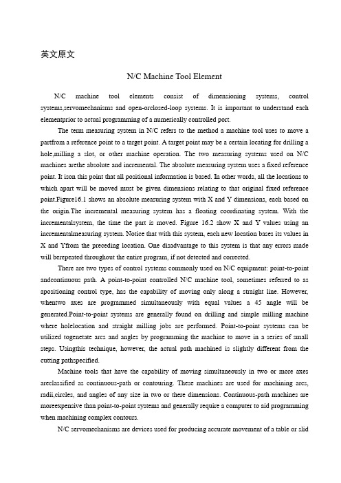
英文原文N/C Machine Tool ElementN/C machine tool elements consist of dimensioning systems, control systems,servomechanisms and open-orclosed-loop systems. It is important to understand each elementprior to actual programming of a numerically controlled port.The term measuring system in N/C refers to the method a machine tool uses to move a partfrom a reference point to a target point. A target point may be a certain locating for drilling a hole,milling a slot, or other machine operation. The two measuring systems used on N/C machines arethe absolute and incremental. The absolute measuring system uses a fixed reference point. It ison this point that all positional information is based. In other words, all the locations to which apart will be moved must be given dimensions relating to that original fixed reference point.Figure16.1 shows an absolute measuring system with X and Y dimensions, each based on the origin.The incremental measuring system has a floating coordinating system. With the incrementalsystem, the time the part is moved. Figure 16.2 show X and Y values using an incrementalmeasuring system. Notice that with this system, each new location bases its values in X and Yfrom the preceding location. One disadvantage to this system is that any errors made will berepeated throughout the entire program, if not detected and corrected.There are two types of control systems commonly used on N/C equipment: point-to-point andcontinuous path. A point-to-point controlled N/C machine tool, sometimes referred to as apositioning control type, has the capability of moving only along a straight line. However, whentwo axes are programmed simultaneously with equal values a 45 angle will be generated.Point-to-point systems are generally found on drilling and simple milling machine where holelocation and straight milling jobs are performed. Point-to-point systems can be utilized togenetate arcs and angles by programming the machine to move in a series of small steps. Usingthis technique, however, the actual path machined is slightly different from the cutting pathspecified.Machine tools that have the capability of moving simultaneously in two or more axes areclassified as continuous-path or contouring. These machines are used for machining arcs, radii,circles, and angles of any size in two or there dimensions. Continuous-path machines are moreexpensive than point-to-point systems and generally require a computer to aid programming when machining complex contours.N/C servomechanisms are devices used for producing accurate movement of a table or slidalong an axis. Two types of servos are commonly used on N/C equipment: electric stepping motors and hydraulic motors. Stepping motor servos are frequently used on less expensive N/C equipment. These motors are generally high-torque power servos and mounted directly to a lead screw of a table or tool slide. Most stepping motors are actuated by magnetic pulses from the stator and rotor assemblies. The net result of this action is that one rotation of the motor shaft produces 200 steps. Connection the motor shaft to a 10-pitch lead screw allows 0.0005-in. movements to be made. Hydraulic servos produce a fluid pressure that flows through gears or pistons to effect shaft rotation. Mechanical motion of lead screws and slides is accomplished through various values and controls from these hydraulic motors. However, they are more expensive and noisy. Most larger N/C machines use hydraulic servos.N/C machines that use an open-loop system contain no-feedback signal to ensure that a machine axis has traveled the required distance. That is, if the input received was to move a particular table axis 1.000 in, the servo unit generally moves the table 1.000 in. There is no means for comparing the actual table movement with the input signal, however, The only assurance that the table has actually moved 1.000 in. is the reliability of the servo system used.Open-loop systems are, of course, less expensive than closed-loop systems. A closed-loop system compares the actual output with the input signal and compensates for any errors. A feedback unit actually compares the amount the table has been moved with the input signal. Some feedback units used on closed-loop systems are transducers, electrical or magnetic scales, and synchros. Closed-loop systems greatly increase the reliability of N/C machines. Machining CentersMany of today’s more sophisticated lathes are called machining centers since they are capable of performing, in addition to the normal turning operations, certain milling and drilling operations. Basically, a machining center can be thought of as being a combination turret lathe and milling machine. Additional features are sometimes included by manufacturers to increase the versatility of their machines.Numerical ControlOne of the most fundamental concepts in the area of advanced manufacturing technologies is numerical control (NC). Prior to the advent of NC, all machine tools were manually operated and controlled .Among the many limitations associated with manual control machine tools, perhaps none is more prominent than the limitation of operator skills. With manual control, the quality of the product is directly related to and limited to the skills of the operator. Numerical control represents the first major step away from human control of machine tools.Numerical control means the control of machine tools and other manufacturing systems through the use of prerecorded, written symbolic instructions. Rather than operating a machine tool, an NC technician writes a program that issues operational instructions to the machine tool. For a machine tool to be numerically controlled, it must be interfaced with a device for accepting and decoding the programmed instructions, known as a reader.Numerical control was developed to overcome the limitation of human operators, and it has done so. Numerical control machines are more accurate than manually operated machines, they can produce parts more uniformly, they are faster, and the long-run tooling costs are lower. The development of NC led to the development of several other innovations in manufacturing technology:1. Electrical discharge machining.2. Laser cutting.3. Electron beam welding.Numerical control has also made machine tools more versatile than their manually operated predecessors. An NC machine tool can automatically produce a wide variety of parts, each involving an assortment of widely varied and complex machining processes. Numerical control has allowed manufacturers to undertake the production of products that would not have been feasible from an economic perspective using manually controlled machine tools and processes. Like so many advanced technologies, NC was born in the laboratories of the Massachusetts Institute of Technology. The concept of NC was developed in the early 1950s with funding provided by the U. S. Air force. In its earliest stages, NC machines were able to make straight cuts efficiently and effectively.However, curved paths were a problem because the machine tool had to be programmed to undertake a series of horizontal and vertical steps to produce a curve. The shorter is the straight lines making up the steps, the smoother is the curve. Each line segment in the steps had to be calculated.This problem led to the development in 1959 of the Automatically Programmed Tools (APT) language. This is a special programming language for NC that uses statements similar to English language to define the part geometry, describe the cutting tool configuration, and specify the necessary motions. The development of the APT language was a major step forward in the further development of NC technology. The original NC systems were vastly different from those used today. The machines had hardwired logic circuits. The instructional programs were written on punched paper, which was later to be replaced by magnetic plastic tape. A tape reader was used to interpret the instructions written on the tape for the machine. Together, all of this represented a giant step forward in the control of machine tools. However, there were a numberof problems with NC at this point in its development.A major problem was the fragility of the punched paper tape medium. It was common for the paper tape containing the programmed instructions to break or tear during a machining process. This problem was exacerbated by the fact that each successive time a part was produced on a machine tool, the paper tape carrying the programmed instructions had to be rerun through the reader. If it was necessary to produce 100 copies of a given part, it was also necessary to run the paper tape through the reader 100 separate times. Fragile paper tapes simply could not withstand the rigors of a shop floor environment and this kind of repeated use.This led to the development of a special magnetic plastic tape. Whereas the paper tape carried the programmed instructions as a series of holes punched in the tape, the plastic tape carried the instructions as a series of holes punched in the tape, the plastic tape carried the instructions as a series of magnetic dots. The plastic tape was much stronger than the paper taps, which solved the problem of frequent tearing and breakage. However, it still left two other problems.The most important of these was that it was difficult or impossible to change the instructions entered on the tape. To make even the most minor adjustments in a program of instructions, it was necessary to interrupt machining operations and make a new tape .It was also still necessary to run the tape through the reader as many times as there were parts to be produced. Fortunately, computer technology became a reality and soon solved the problems of NC associated with punched paper and plastic tape.The development of a concept known as direct numerical control (DNC) solved the paper and plastic tape problems associated with numerical control by simply eliminating tape as the medium for carrying the programmed instructions. In direct numerical control .machine tools are tied, via a data transmission link, to a host computer. Programs for operating the machine tools are stored in the host computer and fed to the machine tool as needed via the data transmission linkage. Direct numerical control represented a major step forward over punched tape and plastic tape. However, it is subject to the same limitations as all technologies that depend on a host computer. When the lost computer goes down, the machine tools also experience downtime. This problem led to the development of computer numerical control.The development of the microprocessor allowed for the development of programmable logic controllers (PLCs) and microcomputers. These two technologies allowed for the development of computer numerical control (CNC).With CNC, each machine tool has a PLC or a microcomputer that serves the same purpose. This allows programs to be input and stored at each individual machine tool. It also allows programs to be developed off-line and downloaded at the individual machine tool. CNC solved the problems associated with downtime of the hostcomputer, but it introduced another known as data management. The same program might be loaded on ten different microcomputers with no communication among them. This problem is in the process of being solved by local area networks that connect microcomputers for better data management.Cutting Tool GeometryShape of cutting tools, particularly the angles, and tool material are very important factors. Angles determine greatly not only tool life but finish quality as well. General principles upon which cutting tool angles are based do not depend on the particular tool, Basically, the same considerations hold true whether a lathe tool, a milling cutter, a drill, or even a grinding wheel are being designed. Since, however the lathe tool, depicted in Fig. 18.1, might be easiest to visualize, its geometry is discussed.Tool features have been identified by many names. The technical literature is full of confusing terminology. Thus in the attempt to cleat up existing disorganized conceptions and nomenclature, this American Society of Mechanical Engineers published ASA Standard B5-22-1950. What follows is based on it.A single-point tool is a cutting tool having one face and one continuous cutting edge, Tool angles identified in Fig. 18.2 are as follows:Tool angle 1, on front view, is the back-rank angle. It is the angle between the tool face and a line parallel to the tool base of the shank in a longitudinal plane perpendicular to the tool base. When this angle is downward from front to rear of the cutting edge, the rake is positive; when upward from front to black, the rake is negative. This angle is most significant in the machining process, because it directly affects the cutting force, finish, and tool life.The side-rake angle, numbered 2, measures the slope of the face on a cross plane perpendicular to the tool base. It, also, is an important angle, because it directs chip flow to the side of the tool post and permits the tool to feed more easily into the work.The end-relief angle is measured between a line perpendicular to the base and the end flank immediately below the end cutting edge; it is numbered 3 in the figure. It provides clearance between work and tool so that its cut surface can flow by with minimum rubbing against the tool. To save time, a portion of the end flank of the tool may sometimes be lest unground, having been previously forged to size. In such case, this end-clearance angle, numbered 4, measured to the end flank surface below the ground portion, would be larger than the relief angle.Often the end cutting edge is oblique to the flank. The relief angle is then best measured in a plane normal to the end cutting edge angle. Relief is also expressed as viewed from side andend of the tool.The side-relief angle, indicated as 5, is measured between the side flank, just below the cutting edge, and a line through the cutting edge perpendicular to the base of the tool. This clearance permits the tool to advance more smoothly into the work.Angle 6 is the end-cutting-edge angle measured between the end cutting edge and a line perpendicular to the side of the tool shank. This angle prevents rubbing of the cut surface and permits longer tool file.The side-cutting-edge angle, numbered 7, is the angle between the side cutting edge and the side of the tool shank. The true length of cut is along this edge. Thus the angel determines the distribution of the cutting forces. The greater the angle, the longer the tool life; but the possibility of charter increases. A compromise must, as usual, be reached.The nose angle, number 8, is the angle between the two component cutting edges. If the corner is rounded off, the arc size is defined by the nose radius 9. The radius size influences finish and chatter.Sand CastingThe first stage in the production of sand castings must be the design and manufacture of a suitable pattern. Casting patterns are generally made from hard word and the pattern has to be made larger than the finished casting size to allow for the shrinkage that takes place during solidification and cooling. The extent of this shrinkage varies with the type of metal or alloy to be cast. For all but the simplest shapes the pattern will be made in two or more pieces to facilitate moulding. If a hollow casting is to be made the pattern design will include extension pieces so that spaces to accept the sand core are moulded into sand. These additional spaces in the mould are termed core prints.Sand moulds for the production of small and medium-sized castings are made in a moulding box. The mould is made in two or more parts in order that the pattern may be removed.The drag half of the mould box is placed on a flat firm board and the drag half of the pattern placed in position. Facing sand is sprinkled over the pattern and then the mould box is filled with moulding sand. The sand is rammed firmly around the pattern. This process of filling and ramming may be done by hand but mould production is automated in a large foundry with the mould boxes moving along a conveyor, firstly to be filled with sand from hoppers and then to pass under mechanical hammers for ramming. When ramming of the sand is complete, excess sand is removed to leave a smooth surface flush with the edges of the moulding box.The completed drag is now turned over and the upper, or cope, portion of the moulding box positioned over it. The cope half of the pattern is placed in position, correct alignment beingensured by means of small dowel pins. Patterns for the necessary feeder, runner and risers are also placed so as to give an even distribution of metal into the mould cavity. The risers should coincide with the highest readily escape from the mould. The sizes of risers should be such that the metal in them does not freeze too rapidly. An important function of a riser is to act as reservoir of liquid metal to feed solidification within the mould. A thin coating of dry parting sand is sprinkled into mould at this stage. This is to prevent the cope and drag sticking together when the cope half is moulded. The cope is now filled with moulding sand and this is rammed firmly into shape in the same manner as in the making of the drag.After the ramming of sand in the cope is completed the two halves of the moulding box are carefully separated. At this stage venting of the moulding box are carefully separated. At this stage venting of the mould can be done, if necessary, to increase the permeability of the mould. After venting the patterns are carefully removed from both cope and drag, and a gate or gates are carefully cut to connect the runner channel with the main cavity. Gates should be sited to allow or entry into mould with a minimum of turbulence. Any loose sand is gently blown away and if a core is to be used it the cope upon the drag and it is then ready for use. Liquid metal is poured smoothly into the mould via the feeder. Pouring ceases when liquid metal appears at the top of the risers and the feeder channel is also full.When the metal that has been poured into a sand mould has fully solidified the mould is broken and casting is removed. The casting still has the runner and risers attached to it and there will be sand adhering to portions of the surface. Runners and risers are cut off and returned to the melting furnace. Sand cores are broken and adherent sand is cleaned from the surface by vibration or by sand blasting with dry sand. Any fins or metal flash formed at mould parting lines are removed by grinding and the castings are then ready for inspection.The main Elements of Horizontal Milling MachinesColumn and baseThe column and base form the foundation of the complete machine. Both are made from cast iron, designed with thick sections to ensure complete rigidity and freedom form vibration. The base, upon which the column is mounted, is also the cutting-fluid reservoir and contains the pump to circulate the fluid to cutting area.The column contains the spindle, accurately located in precision bearings. The spindle id driven through a gearbox from a vee-belt drive from the electric motor housed at the base of column. The gearbox enables a range of spindle speeds to be selected. In the model shown, twelve spindle speeds from 32 to 1400rev/min are available. The front of column carries the guideways upon which the knee is located and guided in a vertical direction.KneeThe knee, mounted on the column guideways, provides the vertical movement of the table. Power feed is available, through a gearbox mounted on the side, from a separate built-in motor, providing a range of twelve feed rates from 12 to 250mm/min. Drive is through a leadscrew, whose bottom end is fixed to machine base. Provision is made to raise and lower the knee by hand through a leadscrew and nut operates by a handwheel at the front. The knee has guideways on its top surface giving full-width support to the saddle and guiding it in a transverse direction. lock is provided to clamp the knee in any vertical position on the column.SaddleThe saddle, mounted on the knee guideways, providers the transverse movement of the table. Power feed is provided through the gearbox on the knee. A range of twelve feeds is available, from 12 to 500mm/min. Alternative hand movement is provided through a leadscrew and nut by a hand heel at the front of the knee.Camping of saddle to the knee is achieved by two clamps on the side of the saddle.The saddle has dovetail gun its upper surface, at right angles to the knee guideways, to provide a guide to the table in a longitudinal direction.TableThe table provides the surface upon which all workpieces and workholding equipment are located and clamped. A series of tee slots is provided for this purpose. The dovetail guides on undersurface locate in the guideways on the saddle, giving straight-line movement to the table in longitudinal direction at right angles to the saddle movement.Power feed is provided from the knee gearbox, through the saddle, to the table leadscrew. Alternative hand feed is provided by a handwheel at each end of the table. Stops at the front of the table can be set to disengage the longitudinal feed automatically in each direction.SpindleThe spindle, accurately mounted in precision bearings, provides the drive for the milling cutters. Cutters can be mounted straight on the spindle nose or in curter-holding devices which in turn are mounted in the spindle, held in position by a drawbolt passing the hold spindle. Spindles of milling machines have a standard spindle nose to allow for easy interchange of cutters and cutter-holding devices. The bore of the nose is tapered to provide accurate location, the angle of taper being 1. The diameter of the taper depends on the size of the machine and may be 30,40,or 50 IST. Due to their steepness of angle, there tapers –known as non-stick or self-releasing- cannot be relied upon to transmit the drive to the cutter or cutter-holding device. Two driving keys are provided to transmit the drive.Overarm and arbor supportDue to the length of arbors used, support is required at the outer end to prevent deflection when cutting takes place. Support is provided by an arbor-support bracket, clamped to an overarm which is mounted on top of the column in a dovetail slide. The overarm is adjustable in or out for different lengths of arbor, or can be fully pushed in when arbor support is not required. Two clamping bolts are support is located in the overarm dovetail and is locked by which the arbor runs during splindle rotation.中文译文数控机床的组成部分数控机床的组成部分包括测量系统、控制系统、伺服系统及开环或闭环系统,在对数控零件进行实际程序设计之前,了解各组成部分是重要的。
关于数控车床编程外文文献翻译中英文翻译外文翻译

关于数控车床编程外文文献翻译、中英文翻译、外文翻译英文原文On the NC latheCNC machine tool numerical control machine tools (Computer numerical control machine tools) abbreviation, is provided with a program control system of automatic machine tools. The logic control system can deal with the control code or other symbolic instruction specified program, and decoding the digital code, said information carrier, through the numerical control device input. After processing by CNC device control signals, control the machine movements, by drawing the shape and size requirements, will be automatically processed by the parts.Features: CNC machine tool operation and monitoring of all completed inthe numericalcontrol unit, it is the brain of CNC machine tools. Compared with the general machine tools, CNC machine tools has the following characteristics:● the processing object adaptability, adapt to the characteristics of mold products such as a single production, provide the appropriate processing method for die and mould manufacturing; ● high machining accuracy, processing with stable quality; ● can coordinate linkage, processing complex shape parts;● machining parts change, only need to change the program, can save the preparation time of production;● the machine itself high precision, rigidity, can choose the am ount of processing good, high productivity (3~5 times as common machine);The machine is a high degree of automation, reducing labor intensity;● conducive to the production management modernization. The use of CNC machine tools and the standard code of digital information processing, information transmission, the use of computer control method, has laid the foundation for the integration of computer aided design, manufacturing and management;● on the operators of higher quality, higher demands for the repair ofthe technical staff;● high reliability.Composition: CNC machine tools in general by the input medium, man-machine interactive equipment, CNC equipment, feed servo drive system, spindle servo drive system, the auxiliary control device, feedback apparatus and adaptive control device etc.. [4] in NC machining, NC milling processing is the most complex, need to solve most problems. NC programming of NC line in addition to CNC milling, cutting, CNC EDM, CNC lathe, CNC grinding, each with its own characteristics, servo system is the role of the motion signal is convertedinto the machine moving parts from the numerical control device of pulse. Concrete has the following parts: the structure of CNC machine tools.Driver: he is driving parts of CNC machine tools, actuator, including spindle drive unit, feeding unit, spindle motor and feed motor. He through the electric or electro-hydraulic servo system to realize the spindle and feeddrive under the control of numerical control device. When several feed linkage, can complete the positioning, processing line, plane curve and space curve.The main performance (1) the main dimensions. (2) the spindle system. (3) feed system. (4) tool system.(5) electrical. Including the main motor, servo motor specifications and power etc.. (6) cooling system. Including the cooling capacity, cooling pump output. (7) dimensions. Expressed as length * width * height.Development trend of CNC lathe:High speed, precision, complex, intelligent and green is the general trend in the development of CNC machine tool technology, in recent years, made gratifying achievements in practicality and industrialization. Mainly in the:1 machine tool composite technology to further expand with the CNC machine tool technology, composite processing technology matures, including milling - car compound, car millingcompound, car - boring - drill - gear cutting compound, composite grinding, forming, composite processing, precision and efficiency of machining isgreatly improved. \processing factory\the development of compound processing machine tool is the trend of diversified.Intelligent technology 2 CNC machine tools have a new breakthrough, in the performance of NC system has been reflected more. Such as: automaticallyadjust the interference anti-collision function, after the power of workpiece automatically exit safety power-off protection function, machining parts detection and automatic compensation function of learning, high precisionmachining parts intelligent parameter selection function, process automatic elimination of machine vibration functions into the practical stage, intelligent upgrade the function of machine and quality.The 3 robots enable flexible combination of flexible combination of higher efficiency of robot and the host are widely used, make flexible line more flexible, extending the function, flexible line shorten further, more efficient. Robot and machining center, milling composite machine, grinder, gear processing machine tool, tool grinding machine, electric machine, sawing machine, punching machine, laser cutting machine, water cutting machine etc. various forms of flexible unit and flexible production line has already begun the application.4 precision machining technology has the machining precision of CNC metal cutting machine tools from the yarn in the original (0.01mm) up to micronlevel (0.001mm), some varieties has reached about 0.05 μ M. Micro cutting and grinding machining of ultra precision CNC machine tools, precision can reach about 0.05 μ m, shape precision can reach about 0.01 μ M. Special processing precision by using optical, electrical, chemical, energy can reach nanometer level (0.001 μ m). By optimizing the design of machine tool structure, machine tool parts of ultra precision machining and precision assembly, using high precision closed loop control andtemperature, vibration and other dynamic error compensation technology, improve the geometric accuracy of machine tool processing, reduce the shape of error, surface roughness, and into the submicron, nano super finishing tiThe 5 functional component to improve the performance of functional components are at a high speed, high precision, high power and intelligent direction, and obtain the mature application. A full digital AC servo motor and drive device, high technology content of the electric spindle, linear motor, torque motor, linear motion components with high performance, application of high precision spindle unit and other function parts, greatly improving the technical level of CNC machine tools.The feed drive system of CNC lathe: Effect of feed drive system,The feed drive system of CNC machine tools will be received pulse command issued by the numerical control system, and the amplification and conversion machine movements carry the expected movement.Two, the feeding transmission system requirementsIn order to guarantee the machining accuracy of NC machine tool is high,the feed drive system of transmission accuracy, sensitivity high (fast response), stable work, high stiffness and friction and inertia small, service life, and can remove the transmission gap. Category three, feed drive system 1, stepping motor servo system Generally used for NC machine tools. 2, DC servo motor servo systemPower is stable, but because of the brush, the wear resulting in use needto change. Generally used for middle-grade CNC machine tools. 3, AC servomotor servo systemThe application is extremely widespread, mainly used in high-end CNC machine tools. 4, the linear motor servo systemNo intermediate transmission chain, high precision, the feed speed, no length limit; but the poor heat dissipation, protection requirements are particularly high, mainly used for high-speed machine.Driving component four, feed system 1, the ball screw nut pairNC machining, the rotary motion into linear motion, so the use of screwnut transmissionmechanism. NC machine tools are commonly used on the ball screw, as shownin Figure 1-25, it can be a sliding friction into rolling friction, meet the basic requirements of the feed system to reduce friction. The transmissionside of high efficiency, small friction, and can eliminate the gap, no reverse air travel; but the manufacturing cost is high, can not lock, size is not too big, generally used for linear feed in small CNC machine tool. 2, rotary tableIn order to expand the scope of the process of NC machine tools, CNC machine tools in addition to make linear feed along the X, Y, Z three coordinate axes, often also need a circumferential feed movement around Y or Z axis. Circular feed motion of CNC machine tools in general by the rotary table to realize, for machining center, rotary table has become an indispensablepart of. Rotary table of commonly used CNC machine tools in the indexing table and NC rotary table. (1) indexing tableIndexing table can only finish dividing movement, not circular feed, it is in accordance with the instructions in the NC system, when indexing will work together with the workpiece rotation angle. When indexing can also use manual indexing. Provisions of indexing table is generally only rotary angle (such as 90, 60 and 45 degree). (2) NC rotary tableNC rotary table appearance similar to the indexing table, but the internal structure and function is not the same. The main function of the NC rotary table is based on the numerical control device sends command pulse signal, complete circumferential feed movement, various arc processing and surface processing, it can also be graduation work. 3, guideRail is an important part of feed drive system, is one of the basic elements of the structure of machine tool, rigidity, precision and accuracy of NC machine tool which determines to a large extent retention. At present, guide the NC machine tool are sliding rail, rolling guideway and hydrostatic guideway. (1) sliding guideSliding guide rail has the advantages of simple structure, easy manufacture, good stiffness, vibration resistance and high performance, widely used in CNC machine tools, the use of most metal plastic form, known as the plastic guide rail, as shown in figure 1-26.On characteristics of the plastic sliding guide: friction characteristicis good, good wear resistance, stable movement, good manufacturability, low speed. (2) rolling guideRolling guide is placed in the rail surface between the ball, roller or needle roller, roller, the rolling friction instead of sliding surface of the guide rail between wipe.Rolling guide rail and the sliding rail, high sensitivity, small friction coefficient, and the dynamic, static friction coefficient is very small, so the motion is uniform, especially in the low speed movement, the stick-slip phenomenon is not easy to occur; high positioning accuracy,repeatability positioning accuracy is up to 0.2 μ m; traction force is small, wear small, portable in movement; good precision, long service life. But the vibration of rolling guide, high requirements on protection, complicated structure, difficult manufacture, high cost.Automatic tool changer:One, the function of automatic tool changerAutomatic tool changing device can help save the auxiliary time of CNC machine tools, and meet in an installation completed procedure, stepprocessing requirements. Two, on the requirement of automatic tool changerNumerical control machine tool for automatic tool changer requirement is: tool change quickly, time is short, high repetitive positioning accuracy, tool storage capacity is sufficient, small occupation space, stable and reliable work. Three, change the knife form 1, rotary cutter replacementIts structure is similar to the ordinary lathe turret saddle, according to the processing of different objects can be designed into square or six angle form, consists of the NC system sends out the instruction to the rotary cutter.2, the replacement of the spindle head tool changeThe spindle head pre-loaded required tools, in order to machining position, the main motor is switched on, drives the cutter to rotate. The advantage of this method is that eliminates the need for automatic clamping, cutting tool, clamping and cutting tool moving and a series of complex operation, reducetool change time, improve The ATC reliability. 3, the use of changing toolThe processing required tools are respectively arranged in the standard tool, adjust the size of the machine after certain way add to the knife, the exchange device from the knife and the spindle take knife switch.感谢您的阅读,祝您生活愉快。
- 1、下载文档前请自行甄别文档内容的完整性,平台不提供额外的编辑、内容补充、找答案等附加服务。
- 2、"仅部分预览"的文档,不可在线预览部分如存在完整性等问题,可反馈申请退款(可完整预览的文档不适用该条件!)。
- 3、如文档侵犯您的权益,请联系客服反馈,我们会尽快为您处理(人工客服工作时间:9:00-18:30)。
原文一CNC machine toolsOutdate, J. and Joe, J. Configuration Synthesis of Machining Centers with Tool,JohnWiley & sons, 2001While the specific intention and application for CNC machines vary from one machine type to another, all forms of CNC have common benefits. Here are but a few of the more important benefits offered by CNC equipment.The first benefit offered by all forms of CNC machine tools is improved automation. The operator intervention related to producing work pieces can be reduced or eliminated. Many CNC machines can run unattended during their entire machining cycle, freeing the operator to do other tasks. This gives the CNC user several side benefits including reduced operator fatigue, fewer mistakes caused by human error, and consistent and predictable machining time for each work piece. Since the machine will be running under program control, the skill level required of the CNC operator (related to basic machining practice) is also reduced as compared to a machinist producing work pieces with conventional machine tools.The second major benefit of CNC technology is consistent and accurate work pieces. Today's CNC machines boast almost unbelievable accuracy and repeatability specifications. This means that once a program is verified, two, ten, or one thousand identical work pieces can be easily produced with precision and consistency.A third benefit offered by most forms of CNC machine tools is flexibility. Since these machines are run from programs, running a different workpiece is almost as easy as loading a different program. Once a program has been verified and executed for one production run, it can be easily recalled the next time the workpiece is to be run. This leads to yet another benefit, fast change over. Since these machines are very easy to set up and run, and since programs can be easily loaded, they allow very short setup time. This is imperative with today's just-in-time (JIT) product requirements.Motion control - the heart of CNCThe most basic function of any CNC machine is automatic, precise, and consistent motion control. Rather than applying completely mechanical devices to cause motion as is required on most conventional machine tools, CNC machines allow motion control in a revolutionary manner2. All forms of CNC equipment have two or more directions of motion, called axes. These axes can be precisely and automatically positioned along their lengths of travel. The two most common axis types are linear (driven along a straight path) and rotary (driven along a circular path).Instead of causing motion by turning cranks and handwheels as is required on conventional machine tools, CNC machines allow motions to be commanded through programmed commands. Generally speaking, the motion type (rapid, linear, and circular), the axes to move, the amount of motion and the motion rate (federate) are programmable with almost all CNC machine tools.A CNC command executed within the control tells the drive motor to rotate a precise number of times. The rotation of the drive motor in turn rotates the ball screw.And the ball screw drives the linear axis (slide). A feedback device (linear scale) on the slide allows the control to confirm that the commanded number of rotations has taken place3. Refer to fig.1.fig.1 typical drive system of a CNC machine toolThough a rather crude analogy, the same basic linear motion can be found on a common table vise. As you rotate the vise crank, you rotate a lead screw that, in turn, drives the movable jaw on the vise. By comparison, a linear axis on a CNC machine tool is extremely precise. The number of revolutions of the axis drive motor precisely controls the amount of linear motion along the axis.How axis motion is commanded - understanding coordinate systemsIt would be infeasible for the CNC user to cause axis motion by trying to tell each axis drive motor how many times to rotate in order to command a given linear motion amount4. (This would be like having to figure out how many turns of the handle on a table vise will cause the movable jaw to move exactly one inch!) Instead, all CNC controls allow axis motion to be commanded in a much simpler and more logical way by utilizing some form of coordinate system. The two most popular coordinate systems used with CNC machines are the rectangular coordinate system and the polar coordinate system. By far, the more popular of these two is the rectangular coordinate system.The program zero point establishes the point of reference for motion commands in a CNC program. This allows the programmer to specify movements from a common location. If program zero is chosen wisely, usually coordinates needed for the program can be taken directly from the print.With this technique, if the programmer wishes the tool to be sent to a position one inch to the right of the program zero point, X1.0 is commanded. If the programmer wishes the tool to move to a position one inch above the program zero point, Y1.0 is commanded. The control will automatically determine how many times to rotate each axis drive motor and ball screw to make the axis reach the commanded destination point . This lets the programmer command axis motion in a very logical manner. Refer to fig.2, 3.fig.2, 3.Understanding absolute versus incremental motionAll discussions to this point assume that the absolute mode of programming is used6. The most common CNC word used to designate the absolute mode is G90. In the absolute mode, the end points for all motions will be specified from the program zero point. For beginners, this is usually the best and easiest method of specifying end points for motion commands. However, there is another way of specifying end points for axis motion.In the incremental mode (commonly specified by G91), end points for motions are specified from the tool's current position, not from program zero. With this method of commanding motion, the programmer must always be asking "How far should I move the tool?" While there are times when the incremental mode can be very helpful, generally speaking, this is the more cumbersome and difficult method of specifying motion and beginners should concentrate on using the absolute mode.Be careful when making motion commands. Beginners have the tendency to think incrementally. If working in the absolute mode (as beginners should), the programmer should always be asking "To what position should the tool be moved?" This position is relative to program zero, NOT from the tools current position.Aside from making it very easy to determine the current position for any command, another benefit of working in the absolute mode has to do with mistakes made during motion commands. In the absolute mode, if a motion mistake is made in one command of the program, only one movement will be incorrect. On the other hand, if a mistake is made during incremental movements, all motions from the point of the mistake will also be incorrect.Assigning program zeroKeep in mind that the CNC control must be told the location of the program zero point by one means or another. How this is done varies dramatically from one CNC machine and control to another8. One (older) method is to assign program zero in the program. With this method, the programmer tells the control how far it is from the program zero point to the starting position of the machine. This is commonly done with a G92 (or G50) command at least at the beginning of the program and possibly at the beginning of each tool.Another, newer and better way to assign program zero is through some form of offset. Refer to fig.4. Commonly machining center control manufacturers call offsets used to assign program zero fixture offsets. Turning center manufacturers commonly call offsets used to assign program zero for each tool geometry offsets.fig.4 assign program zero through G54Flexible manufacturing cellsA flexible manufacturing cell (FMC) can be considered as a flexible manufacturing subsystem. The following differences exist between the FMC and the FMS:1.An FMC is not under the direct control of thecentral computer. Instead, instructions from the centralcomputer are passed to the cell controller.2.The cell is limited in the number of part families itcan manufacture.The following elements are normally found in an FMC:•Cell controller•Programmable logic controller (PLC)•More than one machine tool•A materials handling device (robot or pallet)The FMC executes fixed machining operations with parts flowing sequentially between operations.High speed machiningThe term High Speed Machining (HSM) commonly refers to end milling at high rotational speeds and high surface feeds. For instance, the routing of pockets in aluminum airframe sections with a very high material removal rate1. Refer to fig.5 for the cutting data designations and for mulas. Over the past 60 years, HSM has been applied to a wide range of metallic and non-metallic workpiece materials, including the production of components with specific surface topography requirements and machining of materials with hardness of 50 HRC and above. With most steel components hardened to approximately 32-42 HRC, machining options currently include:Fig.5 cutting datarough machining and semi-finishing of the material in its soft (annealed) condition heat treatment to achieve the final required hardness = 63 HRC machining of electrodes and Electrical Discharge Machining (EDM) of specific parts of dies and moulds (specifically small radii and deep cavities with limited accessibility for metal cutting tools) finishing and super-finishing of cylindrical/flat/cavity surfaces with appropriate cemented carbide, cermets, solid carbide, mixed ceramic or polycrystalline cubic boron nitride (PCBN)For many components, the production process involves a combination of these options and in the case of dies and moulds it also includes time consuming hand finishing. Consequently, production costs can be high and lead times excessive.It is typical in the die and mould industry to produce one or just a few tools of the same design. The process involves constant changes to the design, and because of these changes there is also a corresponding need for measuring and reverse engineering.The main criteria are the quality level of the die or mould regarding dimensional, geometric and surface accuracy. If the quality level after machining is poor and if it cannot meet the requirements, there will be a varying need of manual finishing work. This work produces satisfactory surface accuracy, but it always has a negative impact on the dimensional and geometric accuracy.One of the main aims for the die and mould industry has been, and still is, to reduce or eliminate the need for manual polishing and thus improve the quality and shorten the production costs and lead times.Main economical and technical factors for the development of HSMSurvivalThe ever increasing competition in the marketplace is continually setting new standards. The demands on time and cost efficiency is getting higher and higher. This has forced the development of new processes and production techniques to take place. HSM provides hope and solutions...MaterialsThe development of new, more difficult to machine materials has underlined the necessity to find new machining solutions. The aerospace industry has its heat resistant and stainless steel alloys. The automotive industry has different bimetal compositions, Compact Graphite Iron and an ever increasing volume of aluminum3. The die and mould industry mainly has to face the problem of machining high hardened tool steels, from roughing to finishing.QualityThe demand for higher component or product quality is the result of ever increasing competition. HSM, if applied correctly, offers a number of solutions in thisarea. Substitution of manual finishing is one example, which is especially important on dies and moulds or components with a complex 3D geometry.ProcessesThe demands on shorter throughput times via fewer setups and simplified flows (logistics) can in most cases, be solved by HSM. A typical target within the die and mould industry is to completely machine fully hardened small sized tools in one setup. Costly and time consuming EDM processes can also be reduced or eliminated with HSM.Design & developmentOne of the main tools in today's competition is to sell products on the value of novelty. The average product life cycle on cars today is 4 years, computers and accessories 1.5 years, hand phones 3 months... One of the prerequisites of this development of fast design changes and rapid product development time is the HSM technique.Complex productsThere is an increase of multi-functional surfaces on components, such as new design of turbine blades giving new and optimized functions and features. Earlier designs allowed polishing by hand or with robots (manipulators). Turbine blades with new, more sophisticated designs have to be finished via machining and preferably by HSM . There are also more and more examples of thin walled workpiece that have to be machined (medical equipment, electronics, defense products, computer parts).Production equipmentThe strong development of cutting materials, holding tools, machine tools, controls and especially CAD/CAM features and equipment, has opened possibilities that must be met with new production methods and techniques5.Definition of HSMSalomon's theory, "Machining with high cutting speeds..." on which, in 1931, took out a German patent, assumes that "at a certain cutting speed (5-10 times higher than in conventional machining), the chip removal temperature at the cutting edge will start to decrease...".See fig.6.Fig.6 chip removal temperature as a result of the cutting speedGiven the conclusion:" ... seems to give a chance to improve productivity in machining with conventional tools at high cutting speeds..."Modern research, unfortunately, has not been able to verify this theory totally. There is a relative decrease of the temperature at the cutting edge that starts at certain cutting speeds for different materials.The decrease is small for steel and cast iron. But larger for aluminum and other non-ferrous metals. The definition of HSM must be based on other factors.Given today's technology, "high speed" is generally accepted to mean surface speeds between 1 and 10 kilometers perminute, or roughly 3 300 to 33 000 feet per minute. Speeds above 10 km/min are in the ultra-high speed category, and are largely the realm of experimental metal cutting. Obviously, the spindle rotations required to achieve these surface cutting speeds are directly related to the diameter of the tools being used. One trend which is very evident today is the use of very large cutter diameters for these applications - and this has important implications for tool design.There are many opinions, many myths and many different ways to define HSM. Maintenance and troubleshootingMaintenance for a horizontal MCThe following is a list of required regular maintenance for a Horizontal Machining Center as shown in fig.7. Listed are the frequency of service, capacities, and type of fluids required. These required specifications must be followed in order to keep your machine in good working order and protect your warranty.Fig. 7 horizontal machining centerDailyTop off coolant level every eight hour shift (especially during heavy TSC usage).Check way lube lubrication tank level.Clean chips from way covers and bottom pan.Clean chips from tool changer.Wipe spindle taper with a clean cloth rag and apply light oil.Weekly•Check for proper operation of auto drain on filter regulator. See fig. 8Fig. 8 way lube and pneumaticsOn machines with the TSC option, clean the chip basket on the coolant tank.Remove the tank cover and remove any sediment inside the tank. Be careful to disconnect the coolant pump from the controller and POWER OFF the control before working on the coolant tank. Do this monthly for machines without the TSC option.Check air gauge/regulator for 85 psi.For machines with the TSC option, place a dab of grease on the V-flange of tools. Do this monthly for machines without the TSC option.Clean exterior surfaces with mild cleaner. DO NOT use solvents.Check the hydraulic counterbalance pressure according to the machine's specifications.Place a dab of grease on the outside edge of the fingers of the tool changer and run through all tools".MonthlyCheck oil level in gearbox. Add oil until oil begins dripping from over flow tube at bottom of sump tank.Clean pads on bottom of pallets.Clean the locating pads on the A-axis and the load station. This requires removing the pallet.•Inspect way covers for proper operation and lubricate with light oil, if necessary.Six monthsReplace coolant and thoroughly clean the coolant tank.Check all hoses and lubrication lines for cracking.Annually•Replace the gearbox oil. Drain the oil from the gearbox, and slowly refill it with 2 quarts of Mobil DTE 25 oil.•Check oil filter and clean out residue at bottom for the lubrication chart.Replace air filter on control box every 2 years.Mineral cutting oils will damage rubber based components throughout the machine.TroubleshootingThis section is intended for use in determining the solution to a known problem. Solutions given are intended to give the individual servicing the CNC a pattern to follow in, first, determining the problem's source and, second, solving the problem.Use common senseMany problems are easily overcome by correctly evaluating the situation. All machine operations are composed of a program, tools, and tooling. You must look at all three before blaming one as the fault area. If a bored hole is chattering because of an overextended boring bar, don't expect the machine to correct the fault.Don't suspect machine accuracy if the vise bends the part. Don't claim hole miss-positioning if you don't first center-drill the hole.Find the problem firstMany mechanics tear into things before they understand the problem, hoping that it will appear as they go. We know this from the fact that more than half of all warranty returned parts are in good working order. If the spindle doesn't turn, remember that the spindle is connected to the gear box, which is connected to the spindle motor, which is driven by the spindle drive, which is connected to the I/O BOARD, which is driven by the MOCON, which is driven by the processor. The moral here is doing replace the spindle drives if the belt is broken. Find the problem first; don't just replace the easiest part to get to.Don tinker with the machineThere are hundreds of parameters, wires, switches, etc., that you can change in this machine. Don't start randomly changing parts and parameters. Remember, there is a good chance that if you change something, you will incorrectly install it or break something else in the process6. Consider for a moment changing the processor's board. First, you have to download all parameters, remove a dozen connectors, replace the board, reconnect and reload, and if you make one mistake or bend one tiny pin it WON'T WORK. You always need to consider the risk of accidentally damaging the machine anytime you work on it. It is cheap insurance to double-check a suspect part before physically changing it. The less work you do on the machine the better.译文一数控机床虽然各种数控机床的功能和应用各不相同,但它们有着共同的优点。