龙丘ENC-03陀螺仪模块V1使用手册
胜利仪器 VICTOR 4300智能型三钳数字相位伏安表说明书

目录注意 (2)一.简介 (3)二.型号说明 (3)三.电气符号 (4)四.技术规格 (4)1.基准条件和工作条件 (4)2.一般规格 (5)3.基准条件下基本误差及性能指标 (6)五.仪表结构 (7)六.操作方法 (7)1.开关机 (7)2.背光灯控制 (7)3.数据保持、取消、存储 (7)4.数据查阅、退出 (7)5.数据删除 (8)6.测试显示模式切换 (8)7.测试 (9)七.电池更换 (11)八.其他说明及注意事项 (12)九.配置清单 (13)注意感谢您购买了本公司的VICTOR 4300智能型三钳数字相位伏安表,为了更好地使用本产品,请一定:——详细阅读本用户手册。
——遵守本手册所列出的操作注意事项。
u任何情况下,使用本仪表应注意安全。
u本仪表的RS232-USB接口与内部电路为非隔离接口,严禁在测试电压的时候连接电脑,否则会烧坏仪表或引起触电事故。
必须先将电压测试线拔出仪表后才能连接RS232-USB数据线到电脑读取数据。
说明书中的在线监测不适用于监测电压。
u注意本仪表面板及背板的标贴文字及符号。
u使用前应确认仪表及附件完好,无破损、裸露及断线才能使用。
u不能用于测试高于600V的电压。
u仪表后盖及电池盖板没有盖好禁止使用。
u确定导线的连接插头已紧密地插入接口内。
u仪表于潮湿状态下,请勿使用,或更换电池。
u禁止在易燃性及危险场所测试。
u测试线必须撤离被测导线后才能从仪表上拔出,不能手触输入插孔,以免触电。
u请勿在强电磁环境下使用,以避免影响仪器正常工作。
u不要同时操作2个或2个以上的按键,操作会无效。
u仪表在使用中,机壳或测试线发生断裂而造成金属外露时,请停止使用。
u请勿于高温潮湿,有结露的场所及日光直射下长时间放置和存放仪表。
u仪表及电流钳口必须定期保养,保持清洁,不能用腐蚀剂和粗糙物擦拭钳口。
u避免电流钳受冲击,尤其是钳口接合面。
u仪表具有自动关机功能。
u长时间不用本仪表,请取出电池,更换电池请注意电池极性。
Series WE03 3-Piece Tri-Clamp 钢铁球值说明书

Series WE03 3-Piece Tri-Clamp Stainless Steel Ball ValveSpecifications - Installation and Operating InstructionsBulletin V-WE03The SERIES WE03 incorporates a full port 3-piece tri-clamp SS ball valve for great flow rates with minimal pressure drop. The valve features a blowout proof stem for added safety, reinforced PTFE seats and seals for longer life, and a 316 SS (ASTM CF8M) ball for better performance. Actuators are direct mounted creating a compact assembly for tight spaces. Limit switches are able to be mounted directly to the valves allowing for remote position indication.The Series WE03 can be configured with either an electric or pneumatic actuator. Electric actuators are available in weatherproof or explosion-proof, a variety of supply voltages and two-position or modulating control. Two-position actuators use the supply voltage to drive the valve open or closed, while the modulating actuator accepts a 4 to 20 mA input for valve positioning. Actuators feature thermal overload protection and permanently lubricated gear train.The pneumatic double acting actuator uses an air supply to drive the valve open and closed. The actuator has two supply ports with one driving the valve open and the other driving the valve closed. Spring return pneumatic actuators use the air supply to open the valve and internally loaded springs return the valve to the closed position. Also available is the SN solenoid valve to electrically switch the air supply pressure between the air supply ports for opening and closing the valve. Actuators are constructed of anodized and epoxy coated aluminum for years of corrosion freeservice.WE03-DHD00WE03-DDA01WE03-DDA01-AA06WE03-DDA01-AA07WE03-DTD01-ABy DwyerVALVE BILL OF MATERIALSVALVE DIMENSIONAL DRAWINGAUTOMATED VALVE DRAWINGSW/ PNEUMATIC ACTUATORW/ ELECTRIC ACTUATORW/ EXPLOSION-PROOF ELECTRIC ACTUATORPNEUMATIC ACTUATORNote: For optimal operation, pneumatic actuators should be run with a supply of clean, lubricated air.Spring Return Actuator OperationAir to PORT 2 (the left hand port) causes the actuator to turn counterclockwise (CCW). Loss of air to PORT 2 causes air to exhaust and the actuator turns clockwise (CW). This is the FAIL CLOSE operation.Double Acting Actuators OperationAir to PORT 2 (the left hand port) causes the actuator to turn counterclockwise (CCW). Air to PORT 1 (the right hand port) causes the actuator to turn clockwise (CW).Pneumatic Actuator MaintenanceRoutine maintenance of pneumatic actuator:• Keep the air supply dry and clean• Keep the actuator surface clean and free from dust• Periodic checks should be done to make sure all fittings are tight• Pneumatic actuators are supplied with lubrication to last the entire life span of the actuator under normal operating conditions.The outer surface of the pneumatic actuator should be clean to avoid friction or corrosion. All fittings and connections should be tight to prevent leaks during operation. Check the bolts mounting the valve to the actuator to make sure they have not come loose during shipping or installation. Make sure the valve and actuator are not rubbing or jamming against other components during operation. The actuator should be inspected annually to make sure all fittings and bolts are tight and nothing has come loose during operation.Disassembling Pneumatic ActuatorsBefore beginning disassembly, ensure that the air supply to the actuator has been disconnected, all accessories have beenremoved, and that the actuator has been disassembled from the valve.1. Loosen the end cap fasteners (23) with a wrench (size varies depending on actuator model). On the spring return actuator, alternate 3 to 5 turns on each fastener until the springs are completely decompressed. Use caution when removing the cap since the springs are under load until the fasteners are fully extended.2. Remove the pinion snap ring (13) with a lock ring tool. The indicator (12) may now be removed.3. Turn the pinion shaft (2) counter clockwise until the pistons are at the full end of travel. Disengage the pistons (15) from the pinion. (Note: Low pressure air--3 to 5 psi MAXIMUM--might be required to force the pistons completely from the body.) Note the position of the pistons before removing them from the actuator body.4. Remove the pinion through the bottom of the actuator. The actuator is now completely disassembled.Be sure the actuator surfaces are free of debris and scratches before reassembling.1. Apply a light film of grease to all O-rings and the pinion before replacing.2. Put the pinion (2) back through the actuator with the flats of the pinion shaft running parallel with the body.3. When reassembling the actuator, make sure that the piston racks are square to the actuator body and returned to their original orientation. (Note: The normal operation of all spring return pneumatic actuators is FAIL CLOSED. To change the orientation to FAIL OPEN, rotate the racks 180º to create a reverse operation.4. When replacing springs in a spring return actuator, ensure that the springs are replaced in their identical position in the end cap from which they were removed. (Note: In some circumstances, you might want to change the standard 80 pound spring set to fit your application and available air pressure.5. Seal the end caps with a petroleum lubricant and bolt to actuator body.6. Check the seal of the actuator by covering seal areas (pinion, end caps) with soapy water and using low pressure air to the actuator to ensure that no bubbles are produced.Pneumatic Actuators Bill of MaterialsReassembling Pneumatic ActuatorsELECTRIC ACTUATORSElectric Installation1. Operate valve manually and place in the open position.2. Remove any mechanical stops the valve might have. (DO NOT REMOVE ANY PARTS NECESSARY FOR THE PROPER OPERATION OF THE VALVE, SUCH AS THE PACKING GLAND, PACKING NUT, ETC.)3. Ensure that the actuator output shaft and valve stem are aligned properly. If they are not, operate the valve manually until they are correct.4. Remove actuator cover.5. Bring power to the actuator. CAUTION: Make sure power is OFF at the main box.6. Wire the actuator per the diagram attached to the inside of the cover. Special actuators (those with positioner boards, etc.) will have diagrams enclosed inside the cover.7. Securely tighten bolts used to mount the actuator to a mounting bracket or directly to the valve mounting pad if it is ISO5211 compliant.8. Cycle the unit several times and check the open and closed positions of the valve. Cams are pre-adjusted at the factory; due to the variety of valve designs and types however, slight adjustments might be required.9. Replace cover and tighten screws.To Set The Open Position1. Cycle the valve to the open position by applying power to terminals. The top cam and switch control this position. In the open position, the set screw in the top cam will be accessible.2. If the valve is not open completely:A. Slightly loosen the set screw on the top cam.B. Rotate the cam clockwise (CW) by hand until the switch makes contact. Contact is made when a slight click can be heard. By making incremental CW movements of the top cam, the valve can be positioned precisely in the desired position.C. When the top cam is set, tighten the set screw securely.3. If the valve opens too far:A. Apply power to terminals. This will begin to rotate valve CW. When valve is fully open and in the exact position desired, remove power from actuator.B. Loosen the set screw in the top cam.C. Rotate the top cam counterclockwise (CCW) until the switch arm drops off the round portion of the cam onto the flat section. A slight click can be heard as the switch changes state.D. Continue applying power to terminals until valve is in the desired position.To Set The Closed Position1. Apply power to terminals to move the valve toward the closed position. The bottom cam and switch control the closed position. In the closed position, the set screw in the bottom cam will be accessible.2. If the valve is not closed completely:A. Slightly loosen the set screw on the bottom cam.B. Rotate the cam counterclockwise (CCW) by hand until the switch makes contact. Contact is made when a slight click can be heard. By making incremental CCW movements of the bottom cam, the valve can be positioned precisely in the desired position.C. When the top cam is set, tighten the set screw securely.3. If the valve closes too far:A. Apply power to terminals. This will begin to rotate valve CCW. Whenvalve is fully closed and in the exact position desired, remove power from actuator.B. Loosen the set screw in the top cam.C. Rotate the top cam clockwise (CW) until the switch arm drops off the round portion of the cam onto the flat section. A slight click can be heard as the switch is no longer making contact with the round part of the cam.D. Continue applying power to terminals until valve is in the desired position.Electric Actuators Wiring Diagram: ACT-TI & ACT-MIWiring Diagrams forTI01-A to TI02-A: 110 VAC, TI01-B to TI02-B: 220 VAC, TI01-C to TI02-C: 24 VACHOTALVE ALVEWiring Diagrams for TI01-D to TI02-D: 24 VDCOPERATION:POWER TO 1 & 2 FOR CCW ROTATION POWER TO 3 & 4 FOR CW ROTATION TERMINALS 5 & 6 FOR FIELD LIGHT INDICATION CONNECTIONSW.#1 SW.#2SWITCH #1 OPEN SWITCH SWITCH #2 CLOSE SWITCHWiring Diagrams forMI01-A to MI02-A: 110 VAC, MI01-B to MI02-B: 220 VAC, MI01-C to MI02-C: 24 VACSW. 1, CLOSESW. 2, OPEN .SW. 3, CLOSE SW. 4, OPEN Wiring Diagrams forMI01-D to MI02-D: 24 VDCSW. 1, CLOSESW. 2, OPEN .SW. 3, CLOSE SW. 4, OPENElectric Actuators Wiring Diagram: ACT-TD & ACT-MDWiring Diagrams forTD01-A to TD02-A: 110 VAC, TD01-B to TD02-B: 220 VACTD01-C to TD02-C: 24 VACWiring Diagrams forTD01-D to TD02-D: 24 VDCWiring Diagrams forMD01-A to MD02-A: 110 VAC, MD01-B to MD02-B: 220 VAC,MD01-C to MD02-C: 24 VACNote: To speed up installation of the control wires to the ACT-MDXX modulating actuator, it is recommended to remove the control module from the actuator. The control module can be removed by removing the two mounting screws on the left and right of the control module. Install the control wires to the correct terminal points and then reinstall the control module.Electric Actuator MaintenanceOnce the actuator has been properly installed, it requires no maintenance. The gear train has been lubricated and in most cases will never be opened. Duty Cycle Definition“Duty Cycle” means the starting frequency.Fomula: Running Time ÷ (Running Time + Rest Time) x 100% = duty cycle –> Rest Time = Running Time x (1 - duty cycle) ÷ duty cycleFor example: The running time is 15 seconds30% duty cycle 15 x [(1 - 30%) / 30%] = 35 –> The rest time will be 35 seconds 75% duty cycle 15 x [(1 - 75%) / 75%] = 5 –> The rest time will be 5 seconds If the duty cycle is higher, the rest time will be shortened, which means the starting frequency will be higher.Thermal OverloadAll actuators are equipped with thermal overload protection to guard the motor against damage due to overheating.Mechanical OverloadAll actuators are designed to withstand stall conditions. It is not recommended to subject the unit to repeated stall conditions.Explosion-Proof Electric Actuators1. DO NOT under any circumstances remove the cover of the actuator while in a hazardous location. Removal of the coverwhile in a hazardous location could cause ignition of hazardous atmospheres.2. DO NOT under any circumstances use an explosion-proof electric actuator in a hazardous location that does not meet the specifications for which the actuator was designed.3. Always verify that all electrical circuits are de-energized before opening the actuator.4. Always mount and cycle test the actuator on the valve in a non-hazardous location.5. When removing the cover, care must be taken not to scratch, scar of deform the flame path of the cover and base of the actuator, since this will negate the NEMA rating of the enclosure.6. When replacing the cover, take care that the gasket is in place to assure proper clearance after the cover is secured.7. All electrical connections must be in accordance with the specifications for which the unit is being used.8. Should the unit ever require maintenance, remove from the hazardous location before attempting to work on the unit.If the actuator is in a critical application, it is advisable to have a standby unit in stock.Electric Actuators Performance Rating MAINTENANCE/REPAIRUpon final installation of the Series WE, only routine maintenance is required. The Series WE is not field serviceable and should be returned if repair is needed. Field repair should not be attempted and may void warranty.WARRANTY/RETURNRefer to “Terms and Conditions of Sale” in our catalog and on our website. Contact customer service to receive a Return Goods Authorization number before shipping the product back for repair. Be sure to include a brief description of the problem plus any additional application notes10©Copyright 2015 Dwyer Instruments, Inc.Printed in U.S.A. 10/15FR# 444173-00 Rev. 9。
Fly RC IGyro 飞行器旋转陀螺仪说明书
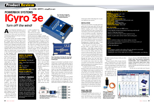
remote gain control which plugs into an openaux channel on your receiver.INSTALLATIONThe IGyro only includes a two page quick startguide and for most users, that is all that willbe required to get the IGyro flying successfully.Without restating much of what I alreadywrote in the May issue, select a location that isconvenient to your receiver, perfectly flat andas free of vibration as possible. Mounting ator near the CG isn’t important, making surethe gyro is perfectly parallel to all three axes is.The direction of flight is indicated in the guideand must be adhered to unless you access thegyro via the terminal program. If you botch amounting pad or change your mind, 1” wide3M VHB mounting tape works perfectly.Once the gyro is mounted you connectthe gain cable to an open channel on yourtransmitter. Initial flight testing should bedone with the gain assigned to a dial or slider.Once you have the settings nailed down thiscan go on a three position switch. The elevatorservo or servos are connected, the aileron servoor servos connected and finally the rudderservo is connected. The IGyro receives powerthrough the receiver bus and only drawsabout 40 mA and is rated for up to 20 amps.I’ve included some screen shots, but unlessyour plane can’t physically accommodate thedefault mounting you’re not going to have toplay with the terminal software.I installed the IGyro on my Habu 32X, notbecause it needs a gyro, but because I put closeto 50 flights on it in course of a month so I wasvery familiar with its flying characteristics. Ilocated the gyro on the floor of the jet next tothe receiver and under the battery tray. I tookcare when building the Habu to balance themotor/fan combo so vibration won’t be anissue. I sanded any imperfections on thebottom of the plane and cleaned the dustaway. I cleaned the bottom of the gyro withalcohol and used the double sided pad tomount the gyro to the bottom of the plane.I tested it for security and neatened up thewiring.RADIO AND GYROCONFIGURATIONThere’s really not that much to do here. AsI said above, pick a channel and assign aknob. My DX-18 beeps as you’re passingcenter which is extremely helpful duringthe flight test phase because it tells you whenthe gyro is off.The gain channel will be at 0 gain when theknob is centered and as you move the knobor slider off center it enters either normal orhold mode depending on which direction youmove, while increasing the gain the furtheryou get from center.Once you have thegain squared away, youare supposed to turnthe gain all the way upin normal mode to setthe gyro direction. BE SURE BEFORE YOUSTART THAT THE RADIO IS PROPERLYCONFIGURED AND EVERYTHING ISGOING THE RIGHT DIRECTION! THENCHECK AGAIN. I actually prefer to use holdmode for the direction test because the surfacewill stay put.Tilt the nose up and make sure the gyro ReviewBY ANDREW GRIFFITH ***************A lot of background information can befound in a two part series on aircraft gyrosin the May 2015 RC Jets column as wellas the Jet Colum in this month’s issue and if you’recontemplating installing your first gyro I encourageyou to read both columns.Power Box Systems has a number of highlyinnovative products built specifically for theRC modeler. Known best for their powerdistribution systems, Power Box Systems has alineup of gyros designed specifically for fixedwing model aircraft. The top of the food chainis the IGyro SRS which is a high tech unit thatstabilizes three axes and has a GPS sensor toadjust the optimum gain on the gyro basedon the current ground speed of the model andit fully integrates withtheir Power Distributionproducts. At the economyend of the spectrum isthe soon to be releasedIGyro 1E that stabilizes asingle flight axis. This isprobably ideal for thoselooking to tame an unrulytail dragger model byusing a small gyro on theyaw axis. In the middleis the IGyro 3E which isthe subject of our review.The 3E is a triple axisgyro, without some of thefancy features of the SRS,but at a more attractiveprice point that is likelyto appeal to a wideraudience. Don’t let thelower price fool you, theIGyro 3E is packed witha number of high endfeatures such as selectableheading or rate mode, fiveservo outputs as well asdelta and V-Tail mixing.The IGyro 3E featuresa triple axis MEMS sensorgyro that is enclosed ina nicely machined two-piece aluminum case.There are five servo inputsand outputs (2 each aileron andelevator and one for rudder), a remotegain control lead and a MISC port that will beused for future expansion. A set of status areLED’s provided on top of the gyro as well asa programming button. A diagram to showthe signal, power and ground orientation ofthe connectors is printed on the bottom of thegyro. There is also a USB port for connectingyour IGyro to a laptop or other device. Aterminal program can be downloaded forfree from the Power Box website that can beused for advanced configuration as well asupdating the firmware on thegyro when new software isreleased. It’s a cool featureand if you’re a techno-geek like me, it will behard to resist playingwith it, but most folkswill be able to configurethe gyro without everhaving to connect it to acomputer.The IGyro 3E has twomodes; heading modeand normal. Normal,also called rate mode,is used to dampenunwanted movementssuch as wind gusts.What makes the IGyrounique is the holdmode and the way theydesigned and included it specifically for fixedwing aircraft. In hold mode with the sticks atneutral, hold mode is engaged on the aileronand elevator axis, but when the sticks aremoved, hold mode disengages and the gyroreverts to rate mode with progressively lessgain as the stick is moved further from center.Flying a fixed wing plane in hold mode takesa little getting used to, but the way the IGyroimplements it works very well.Also included with the gyro are six patchcables to go from your receiver to the gyrofor the channels you’re stabilizing and twodouble side adhesive mounting pads. One ofthose male to male servo cables serves as yourSPECSOPERATING VOLTAGE: 4.0V – 9.0VCURRENT DRAIN: 40 mAMAXIMUM CURRENT LOAD: 20 ASERVO OUTPUTS: 5SERVO SIGNAL RESOLUTION: 0.5 usGYRO MODES: Heading Mode and Normal (rate) modeSENSOR TYPE: MEMSSENSOR AXES: 3 (Roll/Pitch/Yaw)DIMENSIONS: 43mm x 30mm x 15 mmTEMPERATURE RANGE: -30C to 75CKEY FEATURES• Extremely accurate triple-axis MEMS sensor.• Control algorithm designed specifically for fixed wing model aircraft.• Input for in-flight gain adjustment.• 16-bit processor for fast, high-resolution signal processing.• Includes six patch cables and two double sided mounting pads.PROS• Easy to install and configure even without a laptop connection•• Nice anodized aluminum finish• In flight adjustable gainCONS•mounting tape rendering it not visible after installation.•Turn off the wind!NEED TO KNOWMANUFACTURER:DISTRIBUTOR:TYPE:FOR:PRICE:MINIMUM FL YING AREA:NEEDED TO COMPLETE:POWERBOX SYSTEMSIGyro 3e Top of the IGyro showing the servo connections, LED’s, and programming button.Shot of the bottom of the IGyro 3E, the wire pin-out is unfortunately covered by the double sidemounting tape.This diagram shows how the gyro isincorporated to your RC system betweenthe receiver and servos.USB programming cableis available to access theadvanced configurationfunctions and can be used toupdate the firmware as newfeatures become available.The terminal program accesses several advanced configuration optionsto optimize your IGyro including individual channel gains and Delta Wingmixing.gives down elevator. Roll right and make sure the gyro inputs left aileron, nose left and you should see right rudder. The rudder will return to center because it doesn’t use hold mode. If anything is backwards simply press the setup button until all the lights go out. At that point Aileron A will be lit, if that servo is correcting backwards tap the button otherwise hold it and it will move to the next servo. Any servos that need reversed should be and that setting is saved immediately.Perform a full control and gyro direction test again. Then do it with a friend watching to double check. I may sound redundant, but if the gyro is correcting backwards for aileron, for example, and the plane starts rolling right, the gyro will make it roll harder; not correct it. The result will either be having the presence of mind to zero the gain, landing and changing your pants or retrieving the model with a Dust Buster. I’ve seen backwards tail rotor gyros a lot and have done it myself during late night building sessions so I speak from learning the hard way here.FLIGHT TESTINGI couldn’t have asked for a betterday to test the IGyro. The wind wasblowing at 8 to 10mph right downour primary runway, but it was alsoa 90 degree cross wind to our secondrunway that is generally used bythe helicopter and foamie crowd.With the gain set at 0, I advancedthe throttle and took off and nothinghappened. So far so good! With afew mistakes between my Habu andthe ground and about 60-percentpower I advanced the gain until I could see some oscillations which occurred first on the aileron axis. I brought the jet down low at full throttle now that I had my confidence up and tweaked the gain as high as I could get in normal mode at full speed without getting any shimmy. A few laps at both high and low speed gave me the impression that the Habu was flying exactly as before, the difference being that it seemed utterly unperturbed by the wind gusts. I set up for landing and the approach was rock solid right to the ground. I brought the end point down on the normal side so that I could move the lever all the way to the end and swapped a fresh pack in to play with hold mode. I took off again with the gyro in normal mode and the slider all the way forward. Since it doesn’t control the nose wheel I didn’t notice any effect on the ground, but it climbedsmoothly away. I performedthe same procedure as above, slowly raisingthe gain until it oscillated, flying low and fast.Hold mode is really something. Roll invertedin normal and it will slowly arch toward theground, but if you roll inverted in Hold andestablish your line, the plane remains leveland rock solid. Point rolls stop when youlet go and only minor rudder correction isneeded for knife edge where the pitch androll stay put. Flying in Hold mode takes alittle getting used to, but before my timer wastelling me to land I was in a groove.This time I setup my approach on thehelicopter runway with a stiff crosswind.Leaving the gyro in Hold mode, the Habulanded just like I was landing into the wind,albeit with a slightly higher ground speed. Iflew in Hold mode almost exclusively afterthat flight though I did spend a little timedecreasing the end pointand getting the mostgain I could without oscillation. At the end ofthe day I setup the gainon a switch and addeda mix to my gear switch that kicked up the gainby 5 percent when the wheels are down.CONCLUSIONIn calm winds on a good flying plane you mightthink that you wasted your money on a gyro. If the plane is a handful though, you might think you are flying a completely different and well behaved plane.When the wind picks up, however, the plane keeps right on flying the same way … like it’s on rails. Cross wind landing? No problem. A gyro won’t add power when you’re going to stall and it won’t overcome something the airplane isn’t aerodynamically capable of doing. What it will do is make minor corrections at a rate that no human pilot is capable of. How many times do you go to an event and weather is less than ideal? Depending on the distance and the event, that might be a significant investment in time and money. You’ll still be flying with your IGyro at a much higher comfort and enjoyment level. Flying a twin and an engine goes out and you need enough time to get your wits about you? The IGyro will be correcting the rudder before you know you have a problem. Note that I used the IGyro in a ducted fan jet because it tied in nicely with my Jets column, but the IGyro is appropriate in any fixed wing aircraft and I plan on flying it on a few different airframes. To the naysayers that talk about cheating or about the gyro flying the plane, enjoy listening to your 8 track on the way to the field. Flying an IGyro will increase your enjoyment, making you fly more, whichin the end will make you a better pilot. b CONTACTS CHIEF AIRCRAFT ,(800) 447-3408E-FLITE RC , (217) 352-1913SPEKTRUM (217) 352-1913POWER BOX SYTESMS For more information, please see our source guide on page 97.POWERBOX SYSTEMS IGYRO 3EPopup hints explain the various settings and functions.IGyro 3E mounted next to the receiver in my Habu 32x. Before I cleanedup the wiring!The Habu 32X made a great test bed and flew extremely well when the windkicked up. On a calm day it wasn’t even noticiable.。
陀螺全站仪使用说明书
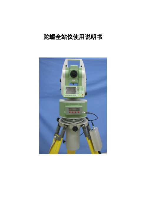
陀螺全站仪使用说明书目次1概述1.1功能和用途1.2主要性能参数2仪器组成3工作原理4使用方法4.1三脚架架设4.2陀螺全站仪主机架设4.3维度输入4.4测量程序4.5数据处理4.6仪器撤收5仪器常数标定5.1仪器常数标定方法5.2仪器常数修正方法6电源使用说明7典型故障及故障排除方法8使用注意事项9维护保养10仪器故障及解决方法1概述1.1功能和用途陀螺全站仪是全自动陀螺仪,其主要功能是提供北向方位基准,可为火炮、雷达提供初始方位基准,并可应用于大地测量、工程测量和矿山贯通测量等领域。
1.2主要性能参数仪器主要技术指标见表1。
表1 陀螺全站仪主要技术指标表2仪器组成产品配套情况见表2。
表2 陀螺全站仪产品配套表3工作原理陀螺全站仪的工作原理是用吊丝悬挂重心下移的陀螺灵敏部敏感地球自转角速度的水平分量,在重力作用下,产生一个北向进动的力矩,使陀螺敏感部主轴(即H向量)围绕子午面往复摆动,通过光电传感器将陀螺灵敏部往复摆动的光信号,转换为电信号,传送给控制系统,控制系统自动跟踪陀螺灵敏部的方位摆动,并对灵敏部进行加矩控制,解算出被测目标的北向方位角。
4使用方法陀螺全站仪主机的使用包括全站仪的使用,全站仪的详细使用方法参见相关全站仪的使用说明书。
4.1三脚架架设在测站架设三脚架,架设时应使三脚架的三个脚尖大致与测点标志中心基本等距,并注意脚架的张角和高度,伸缩脚架腿使圆水准器概略居中。
4.2陀螺全站仪主机架设陀螺全站仪主机架设按以下步骤进行操作。
a.取出陀螺全站仪主机。
三脚架架设完毕后,从包装箱中取出主机(切勿大角度倾斜或倒置),然后将其平稳置于三脚架上。
b.陀螺全站仪主机粗对北。
取出包装箱内的磁罗盘,按照其使用说明书规定的方法,确定当地大致北向;将陀螺寻北仪主机粗对北标记置于大致北向(北向可以借助磁罗盘确定,其使用方法见磁罗盘使用说明书);然后顺时针方向旋转锁紧三脚架上的三个对心手轮。
c.取出锂离子电池,放置在三脚架的固定位置上,然后将2芯电源电缆两端分别与主机和电池连接。
ENC03的使用

ENC03的使用陀螺仪enc03使用心得上次我做一辆小型平衡车时,我用的是陀螺仪(enc03)。
我把测角串口调试视频屏幕放在网上分享。
几天前,一位朋友看到了这个算法,想分享我的经验!首先看datasheet,enc03是个角速度传感器,out管脚输出的电压大小是和它的旋转速度成正比的,知道了速度求路程那就好办了。
让角为D,平均角速度为V,时间为t。
现在,如果已知V和t,有人想读初中物理吗?不要介意。
我把它写在我那双令人敬畏的眼睛上。
d=v*tT可以自己设定。
可通过单片机或其他芯片的定时器进行设置。
T应设置为尽可能小。
如果它太大,不求平均速度的误差将非常大。
我将其设置为100,可以更小。
那么v怎么办呢?看enc03的datasheet可知out管脚的静态电压(就是角速度为0时候电压)为1.35v,角速度每增加1°/s电压增加或减小(有正向速度和反向速度)0.67mv,如图1所示。
图1现在知道out管脚的电压就能算出当时的速度了。
设out管脚电压为u,当时速度为v,那么五、(u?1.35)(/0.67*10-3)但是实际应用中角速度可能是随时变化的,没有一个定值,我们可以算它的平均速度,假设计算了时间点a和B之间陀螺仪的旋转角度,我们首先需要知道a和B之间陀螺仪的平均速度V。
需要求解V。
我们可以测量时间点a的速度VA和时间点B的速度VB,然后:v?(va?vb)/2当a和B之间的时间很短时,V可以非常精确。
根据以上三个公式:d?v*t?va?vbu?ub?2.7*t?a*t?322*0.67*10上面公式中的u是out管脚上的电压,因为它太小,实际应用电路不会直接用ad转换在测量out引脚上的电压时,将根据实际需要添加具有一定放大系数的放大器。
电压U?放大器的输出由AD?转换?,你为什么要这么做?用上述公式计算u。
假如使用如下电路:因此,放大器输出out2的静态电压应通过测量确定。
VREF引脚的电压范围一般为1.25至1.35,设放大器放大倍数为?,放大器输出管脚out2静态电压为v0,放大器输出管脚电压为u?,可得:UA.UB2u0va?vbd?v*t?*t?*T22?*0.67*10?3当然实际应用时还要注意温漂等因数对放大器的静态电压和放大倍数的影响等等,我是在启动初始化程序中加入复测放大器的静态电压,解决静态点漂移问题。
龙丘OLED模块V1快速入门手册

龙丘智能科技中心 龙丘 OLED 模块 V1.1 使用手册(VIP 客户版,第一手资料,请勿外传。
所有资料均以官方数据为准,此文仅供参考, 谢谢! ) 2011 年 9 月 2 日目录目录............................................................................................................................................ 1 1. OLED 简介: ........................................................................................................................ 1 2. 模块外观:........................................................................................................................... 2 3. 模块板子尺寸:................................................................................................................... 2 4. 接线定义之 4 线 SPI 模式: ............................................................................................... 31. OLED 简介:OLED,即有机发光二极管(Organic Light-Emitting Diode),又称 为有机电激光显示(Organic Electroluminesence Display, OELD)。
生物探针3系列操作手册说明书

IMPORTANT! Follow all instructions here before operating the BioHarness 3. Make sure your strap is the correct size before using it (available in two sizes, Small XS-M or Large M-XL). For more details, refer to the BioHarness 3, RAELink3 (or RAELink3 Z1, which has the same functions), and ProRAE Guardian User’s Guides or Quick References.The BioHarness 3 measures the following parameters:Operation1.Moisten the gray sensor pads on the back of the strap with water.2.Snap the BioHarness Echo Module onto the BioHarness 3 by clicking the bottom in first and then the top.3.Power on the BioHarness Echo Module by pressing the button in the center until all four LEDs flash.4.Link the BioHarness Echo Module to the RAELink3.Note: It links automatically after the initial Bluetooth pairing.5.Attach the shoulder strap with Velcro in the back and fit the clasp to the loop in the front, andthen do the same with the clasp and loop in the front.Note: BioHarness Echo Module should be under the left armpit when properly positioned.6.Adjust the shoulder strap and main strap tension by increasing or decreasingthe length of the loop behind the tensioners.unch ProRAE Guardian on your computer. Units come online automatically.Charging The RAELink3Before using the RAELink3, charge its Li-ion battery. For more details, consult the RAELink3 User’s Guide o r Quick Reference.Charging The BioHarness Echo Module1.Snap the BioHarness Echo Module into the Charging Cradle and use a USB cable to connect theCharging Cradle to a computer or the included USB charger.2.Snap the BioHarness Echo Module into the Charging Cradle and allow it to charge. Typicalcharging time for a full charge is 3 hours. A charge of 90% is typically reached in 1 hour. While charging, the BioHarness Echo Module’s orange LED flashes. When fully charged, the orange LED glows continuously.3.Once it is charged, remove the BioHarness Echo Module from the Charging Cradle. Pairing The BioHarness Echo Module And The RAELink3 Via BluetoothAfter an initial pairing of the BioHarness Echo Module with the RAELink3, the two will automatically find each other every time they are turned on. For initial pairing, follow the instructions below.Note: When doing initial pairing, never turn on more than one BioHarness Echo Module and one RAELink3 at the same time.1.Enter Programming Mode on the RAELink3 by holding the [N/-] and [MODE] keys together.∙Press [N/-] twice until you see “OP Mode” (Operation Mode).∙Set the mode of operation to Remote.∙Set the BT (Bluetooth) to BioHarness 3.∙Press [N/-] until you confirm BT (Bluetooth) power is on.Pull tighter or add slack to change lengthof strapTensioner2.Power on the BioHarness Echo Module. Press and hold its Power switch until the all four LEDsflash.3.Perform a BT search using the RAELink3.∙Press [N/-] until you see “Start Bluetooth Search?”∙Press [Y/+] to initiate a search.∙Once the units sync, the serial number of the BioHarness Echo Module is shown in theRAELink3 display with an asterisk next to it.4.Click [MODE] to enter regular operation, and the RAELink3 automatically finds the BioHarness 3.∙When the units link, the blue Bluetooth LED on the BioHarness 3 flashes.∙The RAELink3 LCD indicates that it is linked to the BioHarness 3 by showing the link andthe serial number of the BioHarness 3.Setting The Unit IDThe Unit ID distinguishes between different wireless units within the ProRAE Guardian software. If the Unit ID has not been set to a unique identification number, you must set it.1.Enter Programming Mode on the RAELink3 by holding the [N/-] and [MODE] keys together.2.Press [N/-] until you can set the UNIT ID.3.Select a number between 01 and 64.4.Press and hold [MODE] for two seconds and save it.Defining Alarm LevelsImportant! Alarm limits should only be set after consulting trained medical professionals and getting stress test results for each individual who will be wearing the BioHarness 3.The default alarm template in ProRAE Guardian uses these alarm values:Setting Alarm LevelsFollow these steps to set alarms in ProRAE Guardian for each individual based on the stress test results.1.Under “Options,” choose “Device Templates”:2.Click “Save As” and give a name to the new alarm template.∙Typically, the name of the person who will wear BioHarness 3 (“Test,” in this case).3.Input the alarm levels for the individual, click “Save,” and close the dialog box.4.Within the Device Pane of ProRAE Guardian, right-click on the BioHarness 3 unit that you wantto assign alarms to, and then select “Properties.”5.Choose the saved alarm template from the drop-down menu and then click “Apply.”6.To remove alarm levels from a BioHarness 3, choose “Remove Binding” and then click “Apply.”BioHarness 3 Strap CareThe strap can be hand-washed or machine laundered, following these steps:1.Detach the BioHarness Echo Module.2.Hand wash using a mild soap or detergent or machine wash:∙Cool temperature (40° C/104° F maximum)∙Delicate setting∙Wash pouch recommended∙Spin dry or hang to dry out of direct sunlightIMPORTANT! Do not use bleach or disinfectant. Do not tumble dry. Do not iron. Do not dry-clean.TroubleshootingBioHarness 3 not linking to RAELink3:∙ Make sure the BioHarness Echo Module is charged and turned on. ∙ Make sure the Bluetooth Power is on for the RAELink3.∙ Make sure RAELink3 is set to Remote and BT: BioHarness 3.∙ Confirm that the initial pairing has occurred between RAELink3 and BioHarness Echo Module. ∙ Make sure other BioHarness Echo Modules are not trying to establish a Bluetooth link at the same time.LED indicators:RAELink3 Remote not communicating with ProRAE Guardian software:∙ Confirm that both the HOST RAELink3 modem and the RAELink3 modem connected to the BioHarness 3 have the same NETWORK ID.∙ Confirm the correct communication port (COM port) for the RAELink3 Host modem is selected within ProRAE Guardian software.∙ Make sure the RAELink3 is assigned a unique Unit ID. ∙ Confirm that the RAELink3 is not low on power.Blue LED Bluetooth IndicatorOrange LEDBattery IndicatorRed LEDHeart Rate IndicatorGreen LED Logging IndicatorRev. C May 2014。
龙丘MMA845X模块V1使用手册-VIP版

北京龙邱智能科技有限公司 龙丘 MMA845X 模块 V1.1 使用手册(VIP 客户版,第一手资料,请勿外传。
所有资料均已官方数据为准,次文仅供参考,谢谢! ) 2011 年 9 月 2 日目录MMA845X 系列简介: ....................................................................................................... 2 模块外观: ........................................................................................................................... 3 1.模块板子尺寸: ................................................................................................................ 4 2.接线定义之 IIC 模式:..................................................................................................... 5 3.传感器静止方向加速度数值: ........................................................................................ 6 4.传感器芯片参考电路: .................................................................................................... 7 5.芯片的管脚定义: ............................................................................................................ 8 6.采集的数值处理: ............................................................................................................ 8 7.加速度值转角度: .......................................................................................................... 10 8.用 Z 轴加速度计算偏角角度的处理方法: ................................................................. 11北京龙邱智能科技有限公司 MMA845X 系列简介:MMA8452Q 是一款具有 12 位分辨率的智能低功耗、三轴、电容式微机械加速 度传感器(MMA8451Q 是 14 位分辨力,MMA8453Q 是 10 位分辨力)。
- 1、下载文档前请自行甄别文档内容的完整性,平台不提供额外的编辑、内容补充、找答案等附加服务。
- 2、"仅部分预览"的文档,不可在线预览部分如存在完整性等问题,可反馈申请退款(可完整预览的文档不适用该条件!)。
- 3、如文档侵犯您的权益,请联系客服反馈,我们会尽快为您处理(人工客服工作时间:9:00-18:30)。
北京龙邱智能科技有限公司
龙丘 ENC-03 模块 V1.0 使用手册
(VIP 客户版,第一手资料,请勿外传。
所有资料均以芯片官方数据为准,此文仅供参考,谢谢! ) 2011 年 11 月 20 日
目录
目录 ..........................................................1 1.ENC-03系列简介: ..............................................2 2.必须注意的事项: ..............................................2 3.模块外观: ...................................................3 4.模块板子尺寸: ...............................................4 5.接线定义: ...................................................4 6.传感器静止数值为1.35V,根据旋转方向线性变化: ....................5 7.传感器芯片参考电路: ..........................................6 8.芯片的管脚定义: ..............................................6
模块测试方法:
拿到模块后, (按照目录 5.接线定义)接好 VCC(DC3.3V 或 5V 均可)和 GND, VO1,VO2 静止状态下,输出应该是约 1.35V,随着旋转线性变化者为正常。
否则模块 可能损坏。
一定要注意接线正负极不能错误!
北京龙邱智能科技有限公司 1.ENC-03 系列简介:
该产品是一种应用科氏力原理的角速度传感器,它输出一个和角速度 成正比的模拟电压信号。
■ 特征 1. 特别小的体积和重量 2. 快的响应 3. 低的驱动电压和功耗 测量包含旋转的各种运动。
供电电压Vdc2.7~5.25 最大角速度deg./sec.+/-300 输出(当角速度=0) Vdc1.35 比例系数mV/deg./sec.0.67 线性度%FS+/-5 响应频率Hz50 max. 重量g0.4 操作温度: -5?C to 75?C 储存温度: -30°C to 85°C
2.必须注意的事项:
■ 注意事项储存和操作条件 1. 不要安装传感器在易变形的位置。
.
2
北京龙邱智能科技有限公司
2. 不要安装传感器在温度剧烈变化的位置。
3. 不要使用传感器在剧烈的冲击和振动环境下。
■ 注意事项处理 1. 错误运用可能影响传感器的特性,请注意: 1 不要使传感器受到超过指标的冲击振动。
2 注意防水。
2. 精密电子部分,比如ICs, 被用在传感器上,因此请注意电磁干扰。
■ 注意事项焊接和安装 1. 传感器应该被安装在正确的方向(注意传感器的敏感方向和测量方向一致) 2. 芯片极性一定要准确,否则容易烧毁
3. 严格限制焊接温度, 尽量不要用热风吹 (第一次焊接曾杀死了6个芯片, 心疼! )
3.模块外观:
3
北京龙邱智能科技有限公司 4.模块板子尺寸:
长 X 宽=约 20*26mm
5.接线定义:
右上角为第一脚: pin1、U2 输出,静止状态模拟电压大约是 1.35V,如上图 U1; pin2、U1 输出,静止状态模拟电压大约是 1.35V,如上图 U2; pin3、GND:电源地; pin4、VCC:DC2.7-5.25V;
采集方法:用单片机内部 ADC 采集即可。
4
北京龙邱智能科技有限公司 6.传感器静止数值为 1.35V,根据旋转方向线性变化:
ENC-03MA/MB:
ENC-03RC 封装参数:
5
北京龙邱智能科技有限公司 7.传感器芯片参考电路:
8.芯片的管脚定义:
ENC-03RC 封装参数:
6
北京龙邱智能科技有限公司
ENC-03MA/MB 封装参数:
(图片乃实物照片,请勿传播,由于时间仓促,错误难免,发现错误请联系龙丘科技,谢谢! )
7
北京龙邱智能科技有限公司
请关注最新版本,为您而不断更新…
网站: 淘宝店: 模块链接:/item.htm?id=134********
8
。