变频器说明书施奈德Atv71
施耐德ATV71变频器网络设置手册atv71_devicenet_manual_en_v1
User's manual Retain for future use Altivar 71DeviceNet card VW3 A3 309ContentsBefore you begin_____________________________________________________________________________________________ 3Documentation structure_______________________________________________________________________________________ 4Introduction_________________________________________________________________________________________________ 5 Presentation_____________________________________________________________________________________________ 5 Notation________________________________________________________________________________________________ 5Quick start__________________________________________________________________________________________________ 6Hardware setup_____________________________________________________________________________________________ 7 Receipt_________________________________________________________________________________________________ 7 Hardware description______________________________________________________________________________________ 7 Installing the card in the drive________________________________________________________________________________ 7 Coding the switches_______________________________________________________________________________________ 8Wiring to the network________________________________________________________________________________________ 10 Cable routing practices____________________________________________________________________________________ 10 Wiring the DeviceNet connector_____________________________________________________________________________ 10Configuring by the drive HMI__________________________________________________________________________________ 12 Configuring the control____________________________________________________________________________________ 12 Configuring the communication scanner______________________________________________________________________ 17 Configuring the fault management___________________________________________________________________________ 19 Configuring monitored parameters___________________________________________________________________________ 20Configuring by a network tool__________________________________________________________________________________ 21 Network tool____________________________________________________________________________________________ 21 Going online with RSNetWorx______________________________________________________________________________ 21 Creating an EDS file______________________________________________________________________________________ 21 Configuring the DeviceNet scanner__________________________________________________________________________ 22 Editing parameters of the drive______________________________________________________________________________ 27 Editing objects of the drive_________________________________________________________________________________ 32 Creating a PLC program______________________________________________________________________________________ 35 Using I/O messaging_____________________________________________________________________________________ 35 Using explicit messaging__________________________________________________________________________________ 35 Diagnostics by the drive HMI__________________________________________________________________________________ 36 Checking the node address and the data rate__________________________________________________________________ 36 Signalling LED__________________________________________________________________________________________ 37 Monitoring the control_____________________________________________________________________________________ 38 Monitoring the communication scanner_______________________________________________________________________ 39 Troubleshooting the communication fault______________________________________________________________________ 40 Troubleshooting the card fault______________________________________________________________________________ 41 DeviceNet objects___________________________________________________________________________________________ 42 Supported classes_______________________________________________________________________________________ 42 Identity object___________________________________________________________________________________________ 43 Message router object____________________________________________________________________________________ 46 DeviceNet object_________________________________________________________________________________________ 47 Assembly object_________________________________________________________________________________________ 49 Connection object________________________________________________________________________________________ 60 Motor data object________________________________________________________________________________________ 64 Control supervisor object__________________________________________________________________________________ 65 AC/DC Drive Object______________________________________________________________________________________ 67 Acknowledge handler object________________________________________________________________________________ 68 Application objects_______________________________________________________________________________________ 69 DeviceNet interface object_________________________________________________________________________________ 70 While every precaution has been taken in the preparation of this document, SchneiderElectric SA assumes no liability for any omissions or errors it may contain, nor for anydamages resulting from the application or use of the information herein.The products described in this document may be changed or modified at any time,either from a technical point of view or in the way they are operated. Their descriptioncan in no way be considered contractual.21. Before you beginRead and understand these instructions before performing any procedure with this drive.CAUTIONDAMAGED EQUIPMENTDo not install or operate any drive that appears damaged.Failure to follow this instruction can result in equipment damage.32. Documentation structureThe following Altivar 71 technical documents are available on the Web site and on the CDROM delivered with each drive.b Installation manualThis manual describes:•How to assemble the drive•How to connect the driveb Programming manualThis manual describes:•The functions•The parameters•How to use the drive HMI (integrated HMI and graphic HMI)b Communication parameters manualThis manual describes:•The drive parameters with specific information (addresses, formats, etc.) for use via a bus or communication network•The operating modes specific to communication (state chart)•The interaction between communication and local controlb Modbus, CANopen, Ethernet, Profibus, INTERBUS, Uni-Telway, DeviceNet, Modbus Plus, Fipio, etc., manualsThese manuals describe:•Connection to the bus or network•Configuration of the communication-specific parameters via the integrated HMI or the graphic HMI•Diagnostics•Software setup•The communication services specific to the protocolb Altivar 58/58F migration manualThis manual describes the differences between the Altivar 71 and the Altivar 58/58F.It explains how to replace an Altivar 58 or 58F, including how to replace drives communicating on a bus or network.43. Introduction3. 1. PresentationThe DeviceNet communication card (catalog number VW3 A3 309) is used to connect an Altivar 71 drive to a DeviceNet network.The communication card has an open-style 5-pin connector for connection to the network.Data exchanges give access to all Altivar 71 functions:•Downloading configuration and adjustment parameters,•Command,•Monitoring,•Diagnostics.DeviceNet cables and connecting accessories must be ordered separately.The graphic display terminal or the integrated display terminal can be used to access numerous functions for communication diagnostics.3. 2. NotationDrive terminal displaysThe graphic display terminal menus are shown in square brackets.Example: [1.9 COMMUNICATION].The integrated 7-segment display terminal menus are shown in round brackets.Example: (COM-).Parameter names are displayed on the graphic display terminal in square brackets.Example: [Fallback speed]Parameter codes are displayed on the integrated 7-segment display terminal in round brackets.Example: (LFF).FormatsHexadecimal values are written as follows: 16#Binary values are written as follows: 2#VocabularyDepending on DeviceNet document and tools, equivalent wordings are used. The table below shows vocabulary used in the present document and other corresponding definitions.In this document Other CommentsNode address DeviceNet address, MAC IDData rate Baud ratekbit/s kBPS, kbps, kSetpoint Reference, targetPath Object Address Class, instance, attributeThe reader should avoid mixing two terms:-DeviceNet scanner, which is the master device on the DeviceNet network.-Communication scanner, which is a function inside the Altivar drive.AbbreviationsReq. = RequiredOpt. = Optional54. Quick startThis section is provided to help experienced users quickly start using the DeviceNet card. If you are unsure how to complete a step, refer to the referenced chapter.Step Refer to1Review the safety precautions for the Altivar drive and DeviceNet card.Installation manual2Verify that the Altivar drive is properly installed.Installation manual4Install the DeviceNet card in the drive.Verify that the Altivar drive is not powered.Then, dismount the drive cover, mount the card in the drive. Finally mount the cover.Installation manual4Commission the DeviceNet card.Verify that the Altivar drive is not powered.Set a unique node address and the appropriate data rate using the switches on the card.If desired, you can disable the switches and use parameter settings instead.5. Hardware setup5Connect the drive to the DeviceNet network.Verify that the Altivar drive is not powered.Then, connect the card to the network using a DeviceNet cable.6. Wiring to the network6Apply power to the drive.The card receives power from the drive.Apply power to the drive.The status indicator should be green.If it flashes red, there is a problem(refer to 10. 2. Signalling LED).10. Diagnostics by the drive HMI7Configure the drive for your application.Select the functions and set the parameters as required by your application.Programming manual8Configure the drive behaviour and I/O interface for DeviceNet by the drive HMI.Choose the suitable assemblies for your application (refer to 7. 1. Configuring the control).If assemblies 100 or 101 are used, select the commands assigned to the control word (refer the Programming manual).Set the parameters for the following features as requiredby your application:Control and setpoint channels (refer to 7. 1. Configuring the control),If assemblies 100 or 101 are used, input and output assignments(refer to 7. 2. Configuring the communication scanner),Behaviour on communication fault (refer to 7. 3. Configuring the fault management),The parameters that you would like to monitor by the drive HMI for diagnostics(refer to 7. 4. Configuring monitored parameters).Programming manual Communication parameters manual 7. Configuring by the drive HMI9Apply power to the DeviceNet master and other devices on the network.Verify that the master and network are installed and functioning in accordance with DeviceNet standards, and then apply power to them.DeviceNet master manuals (DeviceNet cable system planning and Installation manual ...)10Configure the scanner to communicate with the drive.Use a network tool such as RSNetWorx for DeviceNet to configure the scanner on the network.Make sure to:Set up the scan list,Map the drive data to the scan list,Save your DeviceNet configuration to the scanner and a file.8. 4. Configuring the DeviceNet scanner11Configure the drive by the network tool.Set the parameters for the following features as required by your application:If the data rate switches (7 and 8) are set to 1, Node address and data rate,If you do not use default assemblies (100 or 101), select (and configure) assemblies.8. 5. Editing parameters of the drive12Create a PLC programControl the drive using I/O (assemblies).Monitor or configure the drive using Explicit Messages.9. Creating a PLC program DeviceNet master manuals65. 1. Receipt•Check that the card reference printed on the label is the same as that on the delivery note corresponding to the purchase order.•Remove the option card from its packaging and check that it has not been damaged in transit.5. 2. Hardware description5. 3. Installing the card in the driveRefer to the Installation manual.Configuration switches (data rate and node address)Bicolour LED785. 4. Coding the switchesb Switches descriptionb Overriding the switchesWhen switches 7 and 8 are set in position low (ON = 1), the data rate and the node address of the drive must be set by a network tool (refer to 8. Configuring by a network tool). Default values are 125 kbit/s and node address 63.b Coding the data rateAll devices connected to the DeviceNet network must communicate at the same data rate: 125, 250, or 500 kbit/s. The table below shows the switch settings that configure the DeviceNet data rate on the drive.Any change to the switch setting takes effect at the next power-up.b Coding the node addressAll devices connected to the DeviceNet network must have a unique address, ranging from 0 to 63 (decimal).If the data rate swithes (7 and 8) are both set to 1 (on), the switches 1 to 6 are ignored and the node address must be set by a network tool (default value = 63).The table below lists the switch setting for each valid node address.Any change to the switch setting takes effect at the next power-up.Switch 7Switch 8Data rate00125 kbit/s 01250 kbit/s 10500 kbit/s11The DeviceNet data rate and the node address of the drive must be set by a network tool.Node address Switches 12 3456Node address Switches 12 3456Node address Switches 12 3456Node address Switches 12 34560000 00001601 00003210 00004811 00000100 00011701 00013310 00014911 00010200 00101801 00103410 00105011 00100300 00111901 00113510 00115111 00110400 01002001 01003610 01005211 01000500 01012101 01013710 01015311 01010600 01102201 01103810 01105411 01100700 01112301 01113910 01115511 01110800 10002401 10004010 10005611 10000900 10012501 10014110 10015711 10011000 10102601 10104210 10105811 10101100 10112701 10114310 10115911 10111200 11002801 11004410 11006011 11001300 11012901 11014510 11016111 11011400 11103001 11104610 11106211 11101500 11113101 11114710 11116311 1111rateaddresshight = OFF = 0low = ON = 19bExamplesData rate = 250 kbit/s (switches 7 and 8 = 2#01)Node address = 25 (switches 1 to 6 = 2#01 1001)Data rate = 500 kbit/s (switches 7 and 8 = 2#10)Node address = 52 (switches 1 to 6 = 2#11 0100)106. Wiring to the network6. 1. Cable routing practicesWhen wiring Altivar 71 drives to a DeviceNet network, follow all wiring practices required by national and local electrical codes. Also observe the following guidelines:•Avoid areas of high temperature, moisture, vibration, or other mechanical stress.•Secure the cable where necessary to prevent its weight and the weight of other cables from pulling or twisting the cable.•Use cable ducts, raceways, or other structures to protect the cable. Use these structures for signal wiring paths. They must not contain power wiring.•Avoid sources of electrical interference that can induce noise into the cable. Use the maximum practicable separation from such sources.When planning cable routing within a building, follow these guidelines:•Maintain a minimum separation of 1 m from the following equipment:-air conditioners and large blowers,-elevators and escalators,-radios and televisions,-intercom and security systems,-fluorescent, incandescent, and neon lighting fixtures.•Maintain a minimum separation of 3 m from the following equipment:-line and motor power wiring,-transformers,-generators,-alternators.When wiring in electrical equipment rooms or large electrical equipment line-ups, observe the following guidelines for cable segregation and separation of circuits:•Use metallic conduit for drive wiring. Do not run control network and power wiring in the same conduit.•Separate non-metallic conduits or cable trays used to carry power wiring from metallic conduit carrying low-level control network wiring by at least 300 mm.•Separate metallic conduits carrying power wiring or low-level control network wiring by at least 80 mm.•Cross the metallic conduits and non-metallic conduits at right angles whenever power and control network wiring cross.•Attenuate conducted emissions from the drive to the line in some installations to prevent interference with telecommunication, radio, and sensitive electronic equipment. Such instances may require attenuating filters. Consult the Altivar catalog for selection and application of these filters.6. 2. Wiring the DeviceNet connectorThe figures and the table below show the pin-outs of the card connectors. The removable DeviceNet female connector attaches to the network cable.Line termination: If the drive is the first or the last device on the DeviceNet network, a line terminator (121 Ω resistor) must be wired on the removable DeviceNet female connector, between pins 2 and 4 (CAN_L and CAN_H).DeviceNet card male connector Removable DeviceNet female connectorPin Name Color 1GND Black 2CAN_L Blue 3SHIELD Bare 4CAN_H White 5V+Red6. Wiring to the networkThe ODVA standards (Release 2.0) specify 7 types of cables for use in DeviceNet networks:•Thick cable•Thin cable•Flat cable•Cable I•Cable II•Cable IV•Cable VThe table below lists main specifications of cables. For more information, refer to the ODVA specifications.Type of cable Data conductor pair size Power conductor pair size Data impedanceThick cable18 AWG15 AWG120 Ω +/- 10 % (at 1 MHz) Thin cable24 AWG22 AWG120 Ω +/- 10 % (at 1 MHz) Flat cable16 AWG16 AWG120 Ω +/- 10 % (at 500 kHz) Cable I24 AWG22 AWG120 Ω +/- 10 % (at 1 MHz) Cable II18 AWG15 AWG120 Ω +/- 10 % (at 1 MHz) Cable IV18 AWG16 AWG120 Ω +/- 10 % (at 500 kHz) Cable V18 AWG16 AWG120 Ω +/- 10 % (at 500 kHz)The maximum permissible length of the network cable depends an the data rate and the type of cable.Type of cable Data rate125 kbit/s250 kbit/s500 kbit/sThick cable500 m (1640 ft)250 m (820 ft)100 m (328 ft)Thin cable100 m (328 ft)100 m (328 ft)100 m (328 ft)Flat cable420 m (1378 ft)200 m (656 ft)75 m (246 ft)Cable I100 m (328 ft)100 m (328 ft)100 m (328 ft)Cable II500 m (1640 ft)250 m (820 ft)100 m (328 ft)Cable IV---Cable V420 m (1378 ft)200 m (656 ft)75 m (246 ft)For maximum length of the drops refer to table, whatever type of cable:Data rate Cumulative drop Maximum drop125 kbit/s156 m (516 ft) 6 m (20 ft)250 kbit/s78 m (256 ft) 6 m (20 ft)500 kbit/s39 m (128 ft) 6 m (20 ft)7. 1. Configuring the controlb PrincipleBy the configuration of the control, it is possible to decide from what channel the drive receives its commands and setpoint, either permanently or depending on a switching command.Numerous configurations are possible. For more information, refer to the Programming manual and Communication parameters manual. The following configurations are some of the possibilities available.M Control with communication scannerIf the default assemblies (100, 101) are selected, all possibilities of Altivar 71 drive are available.It is possible to use all profiles and modes of the drive:-I/O profile,-Drivecom profiles with separate or non separate mode.By the configuration of the communication scanner, it is possible to assign any relevant parameter of the drive to the 4 input and 4 output variables of the assemblies.See the input / output interface with the PLC can be fully customised depending on the application.The use of the communication scanner is als the best way to interface with a "Controller Inside" card.M Control according to ODVA AC drive profileThe ODVA AC drive profile is activated when one of the following assemblies is selected:•20: Basic speed control output•21: Extended speed control output•22: Speed and torque control output•23: Extended speed and torque control output•70: Basic speed control input•71: Extended speed control input•72: Speed and torque control input•73: Extended speed and torque control inputThe advantage of using the ODVA drive profile standard is the interchangeability with other brands.The drive must be configured in the Drivecom profile with separate mode.The DeviceNet card translates the commands, behaviour and monitoring information from of ODVA profile (on the network) to the Drivecom profile (in the drive).M Control according to Allen-Bradley® drive profileThe Allen-Bradley® Drive profile is activated when one of the following assemblies is selected:•103: Allen-Bradley® drive output•104: Allen-Bradley® drive input•105: Allen-Bradley® drive input with parametersIf you need to replace Allen-Bradley® drives, in an existing application, this profile is a good way to minimise the modifications.The drive must be configured in the Drivecom profile with separate mode.The DeviceNet card translates the commands, behaviour and monitoring information from of Allen-Bradley® drive profile (on the network) to the Drivecom profile (in the drive).b Available configurationsM If you use the communication scanner:•100: Communication scanner output•101: Communication scanner input there is no limitation in the configuration of the control.The examples below are only possible if you use the communication scanner.M If you use the ODVA AC drive profile or Allen-Bradley® Drive profile, that is, the assemblies:•20: Basic speed control output •21: Extended speed control output •22: Speed and torque control output•23: Extended speed and torque control output •70: Basic speed control input •71: Extended speed control input •72: Speed and torque control input•73: Extended speed and torque control input •103: Allen-Bradley® drive output •104: Allen-Bradley® drive input•105: Allen-Bradley® drive input with parameters only some configurations are permitted, they are listed in the table below.Configuration via the graphic display terminal or the integrated display terminal:Case 1: Setpoint 1B is connected to the functions (Summing, PID, etc) which remain active even after switching.Case 2: Setpoint 2 is directly connected to the drive reference limit. If switching is performed, the functions that affect the reference (summing, PID, etc.) are inhibited.Note: It is not possible to configure the display terminal as a channel.To switch to the display terminal, use the function force local and assign the parameter [Forced local Ref.] to [HMI] (LCC ).Parameter Permitted valueCommentProfileDrivecom profile separate The run commands are in Drivecom profile,the command and the reference can come from different channels.Setpoint 1 configuration Network card Setpoint 1 comes from DeviceNet.Setpoint 1B configuration Terminals Setpoint 2 comes from terminals (AI1 or AI2).Setpoint 2 configuration Terminals Setpoint 2 comes from terminals (AI1 or AI2).Command 1 configuration Network card Command 1 comes from mand 2 configuration TerminalsCommand 2 comes from terminals.Setpoint switching Network card bit 12Bit 12 of the control word switches the setpoint (1 <-> 1B or 1 <-> 2).Command switchingNetwork card bit 13Bit 13 of the control word switches the command.Menu Parameter Permitted value [1.6 - COMMAND] (CtL-)[Profile] (CHCF )[Separate] (SEP )[Ref.1 channel] (Fr1)[Com. card] (nEt )[Ref.1B channel] (Fr1b )[Ref. AI1] (AI1) or [Ref. AI2] (AI2)[Cmd channel 1] (Cd1)[Com. card] (nEt )[Cmd channel 2] (Cd2)[Terminals] (tEr )[Cmd switching] (CCS )[C312] (C312)[1.7 APPLICATION FUNCT.] (F Un-)[REFERENCE SWITCH.][Ref 1B switching] (rCb )[C313] (C313)Menu Parameter Permitted value [1.6 - COMMAND] (CtL-)[1.7 APPLICATION FUNCT.] (FUn-)[REFERENCE SWITCH.][Profile] (CHCF )[Separate] (SEP )[Ref.1 channel] (Fr1)[Com. card] (nEt )[Ref.2 channel] (Fr2)[Ref. AI1] (AI1) or [Ref. AI2] (AI2)[Cmd channel 1] (Cd1)[Com. card] (nEt )[Cmd channel 2] (Cd2)[Terminals] (tEr )[Cmd switching] (CCS )[C312] (C312)[Ref. 2 switching] (rFC )[C313] (C313)b Control via DeviceNet in I/O profileNote: This configuration can only be used if the communication scanner assemblies (100 and 101) are selected.The command and the setpoint come from DeviceNet.Control is in I/O profile.Configure the following parameters:Configuration via the graphic display terminal or the integrated display terminal:b Control via DeviceNet or via the terminals in I/O profileNote: This configuration can only be used if the communication scanner assemblies (100 and 101) are selected.The command and the setpoint both come from DeviceNet or the terminals. Input LI5 at the terminals is used to switch between DeviceNet and the terminals.Control is in I/O profile.Configure the following parameters:Note: Setpoint 1B is connected to the functions (Summing, PID, etc) which remain active even after switching.Configuration via the graphic display terminal or the integrated display terminal:Parameter Value CommentProfileI/O profileThe run command is simply obtained by bit 0 of the command word.Setpoint 1 configuration Network card The setpoint comes from mand 1 configurationNetwork card The command comes from DeviceNet.MenuParameter Value[1.6 - COMMAND] (CtL-)[Profile] (CHCF )[I/O profile] (IO )[Ref.1 channel] (Fr1)[Com. card] (nEt )[Cmd channel 1] (Cd1)[Com. opt card] (nEt )Parameter Value CommentProfileI/O profile The run command is simply obtained by bit 0 of the control word.Setpoint 1 configuration Network card Setpoint 1 comes from DeviceNet.Setpoint 1B configuration Analog input 1 on the terminals Setpoint 1B comes from input AI1 on the terminals.Setpoint switching Input LI5Input LI5 switches the setpoint (1 ↔1B).Command 1 configuration Network card Command 1 comes from mand 2 configuration Terminals Command 2 comes from the mand switchingInput LI5Input LI5 switches the command.MenuParameter Value[1.6 - COMMAND] (CtL-)[Profile] (CHCF )[I/O profile] (IO )[Ref.1 chan] (Fr1)[Com. card] (nEt )[Cmd channel 1] (Cd1)[Com. card] (nEt )[Cmd channel 2] (Cd2)[Terminals] (tEr )[Cmd switching] (CCS )[LI5] (LI5)[1.7 APPLICATION FUNCT.] (FUn-)[REFERENCE SWITCH.][Ref.1B chan] (Fr1b )[AI1 ref.] (AI1)[Ref 1B switching] (rCb )[LI5] (LI5)b Control via DeviceNet in Drivecom profileNote: This configuration can only be used if the communication scanner assemblies (100 and 101) are selected.The command and the setpoint come from DeviceNet.Configure the following parameters:Parameter Value CommentProfile Separate Drivecom profile The run commands are in Drivecom profile, the command and the setpoint cancome from different channels.Setpoint 1 configuration Network card The setpoint comes from DeviceNet.Command 1 configuration Network card Command 1 comes from DeviceNet.Configuration via the graphic display terminal or the integrated display terminal:Menu Parameter Value[1.6 - COMMAND](CtL-)[Profile](CHCF)[Separate](SEP)[Ref.1 chan](Fr1)[Com. card](nEt)[Cmd channel 1](Cd1)[Com. card](nEt)b Control via DeviceNet or the terminals in Drivecom profileNote: This configuration can only be used if the communication scanner assemblies (100 and 101) are selected.The command and the setpoint both come from DeviceNet or the terminals. Input LI5 at the terminals is used to switch between DeviceNet and the terminals.Configure the following parameters:Parameter Value CommentProfile Separate Drivecom profile The run commands are in Drivecom profile, the command and thesetpoint can come from different channels.Setpoint 1 configuration Network card Setpoint 1 comes from DeviceNet.Setpoint 2 configuration Analog input 1 on the terminals Setpoint 2 comes from input AI1 on the terminals.Setpoint switching Input LI5Input LI5 switches the setpoint (1 ↔ 2) and the command.Command 1 configuration Network card Command 1 comes from DeviceNet.Command 2 configuration Terminals Command 2 comes from the terminals.Command switching Input LI5Input LI5 switches the command.Note: Setpoint 2 is directly connected to the drive reference limit. If switching is performed, the functions that affect the reference (summing, PID, etc) are inhibited.Configuration via the graphic display terminal or the integrated display terminal:Menu Parameter Value[1.6 - COMMAND](CtL-)[Profile](CHCF)[Separate](SEP)[Ref.1 chan](Fr1)[Com. card](nEt)[Ref.2 chan](Fr2)[AI1 ref.](AI1)[Ref. 2 switching](rFC)[LI5](LI5)[Cmd channel 1] (Cd1)[Com. card](nEt)[Cmd channel 2](Cd2)[Terminals](tEr)[Cmd switching](CCS)[LI5](LI5)。
施耐德变频器(ATV71L)调试说明
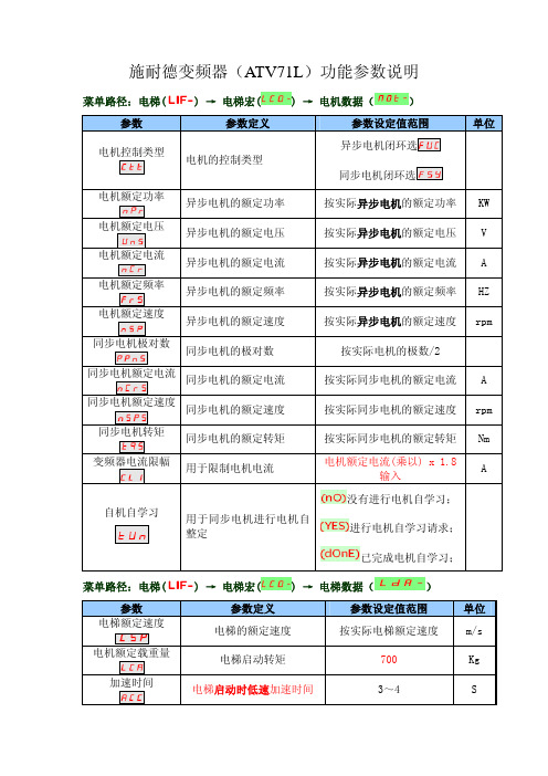
施耐德变频器(ATV71L)功能参数说明菜单路径:电梯()→电梯宏() →电机数据()参数 参数定义 参数设定值范围单位电机控制类型电机的控制类型异步电机闭环选同步电机闭环选电机额定功率异步电机的额定功率 按实际异步电机的额定功率KW电机额定电压异步电机的额定电压 按实际异步电机的额定电压 V电机额定电流异步电机的额定电流 按实际异步电机的额定电流 A电机额定频率异步电机的额定频率 按实际异步电机的额定频率 HZ电机额定速度异步电机的额定速度 按实际异步电机的额定速度 rpm同步电机极对数同步电机的极对数 按实际电机的极数/2同步电机额定电流同步电机的额定电流 按实际同步电机的额定电流 A同步电机额定速度同步电机的额定速度 按实际同步电机的额定速度 rpm同步电机转矩同步电机的额定转矩 按实际同步电机的额定转矩 Nm变频器电流限幅用于限制电机电流电机额定电流(乘以) x 1.8输入A自机自学习用于同步电机进行电机自整定没有进行电机自学习;进行电机自学习请求;已完成电机自学习;菜单路径:电梯()→电梯宏() →电梯数据()参数 参数定义 参数设定值范围 单位电梯额定速度电梯的额定速度 按实际电梯额定速度 m/s电机额定载重量电梯启动转矩 700 Kg加速时间电梯启动时低速加速时间 3~4 S减速时间电梯减速停车段的减速时间12~30 (12) S 加速始端圆滑系数加速斜坡开始平滑时间 50%加速未端圆滑系数加速斜坡结束平滑时间 50%减速始端圆滑系数减速斜坡开始平滑时间 40%减速未端圆滑系数减速斜坡结束平滑时间 40%斜坡2切换阀值第二段斜坡曲线开始速度设置成电梯的爬行速度(数值=SP3内的值)HZ第2加速时间第2段曲线高速段加速时间3~6 S第2减速时间第2段曲线减速段时间2.0~5 (3.0)(只适用于≤1米梯速)S菜单路径:电梯()→电梯优化() →速度环() 参数 参数定义 参数设定值范围 单位频率F环稳定性速度环比例增益,调整速度瞬变返回到稳定状态的增益20%频率环增益速度环的积分增益时间,调整速度瞬变的响应时间20%速度环滤波系数异步电机设65 同步电机设100编码器滤波激活编码器滤波常数3 ms 菜单路径:设置()参数 参数定义 参数设定值范围 单位高速频率电机的额定频率(电梯的额定速度)电机的额定频率 HZ菜单路径:电机控制()参数 参数定义 参数设定值范围 单位 最大输出频率电梯超速保护值 电机的额定频率*1.1 HZ菜单路径:电梯()→电梯功能() →预设速度()参数 参数定义 参数设定值范围 单位预设速度3爬行速度按0.06m/s的速度换算成频率HZ预设速度4SP 4多段速3(三层运行速度)按1.5m/s~1.75m/s的速度换算成频率 * 0.95HZ预设速度5检修速度按 0.2m/s的速度换算成频率 * 0.95HZ预设速度6多段速1(单层运行速度)按1.0m/s的速度换算成频率 * 0.95预设速度7多段速2(两层运行速度)按1.5m/s的速度换算成频率 * 0.95HZ预设速度8多段速4(四层运行速度)按2.0m/s的速度换算成频率 * 0.95电梯起动舒适感调整:菜单路径:电梯()→电梯优化() →起动调整()→刹车起动()参数 参数定义 参数设定值范围 单位 刹车机构释放时间刹车机构释放时间延时 1.0 S 刹车释放电流l b r刹车机构释放电流值(-5,-10,+10,+5)约30~50%额定电流值A 制动力方向刹车释放电流功能打开或关闭功能打开菜单路径:电梯()→电梯优化() →起动调整()→倒溜管理()参数 参数定义 参数设定值范围 单位 倒溜管理倒溜管理功能打开或关闭倒溜补偿倒溜补偿增益 10~200% (40)倒溜缓冲倒溜阻尼系数 30~100% (50)起始刚度补偿起始刚度补偿 功能打开或关闭激活角度启激活角度系数1~10% (1)刚度增益刚度增益 40~200% (60)电梯停止时舒适感的调整:一.电梯速度≤ 1.0m/s : 减小减速时间可以增大爬行距离;二.电梯速度>1.0m/s :单层运行冲层 减小减速时间 减速太快,有冲层现象多层运行冲层减小减速时间一.电梯速度≤1.0m/s : 增大减速时间可以减小爬行距离; 二.电梯速度>1.0m/s :单层运行爬行太长增大减速时间 减速太慢,爬行太长多层运行爬行太长增大减速时间停止有倒溜停止时有振动① 有倒溜时,增加刹车抱紧时间② 确认bECd 是否设为0.0s③停止时有提升感,加大减速时间菜单路径:电梯() → 电梯优化() → 停止调整()参数 参数定义 参数设定值范围单位 bECd零速抱闸时间 0.0 s抱闸抱紧时间0.5s★ 电梯减速时间调整方法:① 菜单路径:电梯() → 电梯功能() → 频率阀值()参数 参数定义参数设定值范围单位 频率阀值设置减速时间的切换频率单层运行的速度值 HZ备注:如电梯速度≤1.0m/s :可设置为一半的数值② 菜单路径:电梯() → 电梯功能() → 参数组切换()参数 参数定义参数设定值范围 单位 2组参数组设置切换2组参数组的内容到频率阀值 HZ选择参数SPS选择此参数组,只能用液晶操作器设定第2减速时间第1组0~频率阀值的单层速度的减速时间4.5~6 S第2组频率阀值~最高速的多层速度减速时间3~5S备注:如电梯速度≤1.0m/s 时,数值不变,为曲线段减速时间监控参数: 端子状态监控:菜单路径:监视() → 输入/输出映像()→逻辑输入LI1至LI8的状态( LI5I- )参数 参 数 说 明逻辑输入LI1~LI8状态1亮表示该信号动作,状态0亮表示该信号不动作 电机运行电流监控: 菜单路径:监视() →电流()1. 施耐德变频器(ATV71L )1.1施耐德变频器电机自学习时的故障显示:故障代码 名称 故障原因 检查措施负载不跟随 编码器反馈速度与给定值不相符1.检查主机编码器;2.重新做主机自学习;角度值误差 电机编码器角度学习不正确 1.确认变频器与电机连接线是否正确;2.确认KMY 接触器接触是否良好; 3.确认主机编码器安装是否牢固;4.重新执行电机自学习;配置错误 变频器PG 卡故障; 1.检修PG 卡接触是否良好;2.更换变频器PG 卡; 编码器故障 编码器反馈故障1.检查变频器内编码器设定的参数;2.检查编码器的连接线;过电流 负载太大电机控制()菜单中最大输出频率设定值不对1.检查负载;2.检查最大输出频率的设定值;电机短路接地短路变频器输出侧短路或接地检查变频器侧输出侧的连接线;超速 驱动负载不稳定或负载太大1.检查编码器接线和抗干扰处理是否正常;2.检查速度环的比例增益设定是否合适;3. 检查编码器是否正常;速度反馈丢失 没有编码器反馈信号 编码器连接线有干扰1.检查编码器的连接线;2.检查编码器连接线的屏蔽层接地是否良好,接到ST-1分频卡上的线接触是否良好;Brake 控制 没有达到刹车释放电流1.检查电机的动力线连接是否正确,有无虚接现象;2.检查KMY 接触器主触点接触是否良好,动力线有无虚接现象;3.检查是否由于厅门锁回路瞬间断开所致;变频器过热 变频器温度太高1.检查变频器的通风情况及周围温度;2.检查变频器的散热风扇运行是否正常;变频器过载 负载电流太大1.检查负载情况;2.检查电机热保护的设置值是否正确;输出缺1相输出缺3相变频器输出缺相1.检查变频器输出端的连接线;2.检查KMY运行接触器; 输入过电压主回路电压太高;电源不稳定有波动;输入缺相 变频器输入缺相输入欠压 变频器输入电压太低检查变频器的输入电源电源切除变频器PWR使能信号端无输入信号自由停车 变频器故障后自由停车模式检查主板到PWR端的连接线IGBT过热 变频器过载1.减小载波频率;2.检查负载情况;3.交换电机的V、W动力线,重新做主机自学习;4.检查安装主机编码器;。
施耐德ATV71变频器设置指南

施耐德ATV71变频器设置指南施耐德ATV71变频器是一种专业的电气控制设备,用于控制电动机的转速和运行。
在使用ATV71变频器之前,我们需要了解如何正确设置和调试它以确保最佳性能和安全运行。
以下是施耐德ATV71变频器的设置指南,包括安装、接线、参数设置和调试过程。
第一步:安装和接线1.根据变频器的额定功率和电压,选择适当的安装位置。
2.确保变频器周围的环境通风良好,并远离热源和湿度。
3.确保电源线和电机线接线正确,按照变频器的接线图进行连接。
在连接电源线和电机线之前,确保电源已经断开。
4.检查接线是否牢固,并避免电线交叉和短路。
第二步:参数设置1.连接电源后,按下变频器面板上的“模式”按钮,进入基本设置菜单。
2.使用上下/左右箭头键导航到所需的参数设置,按下“确定”键进行选择。
3.根据实际应用需求,设置变频器的基本参数,如额定电压、额定功率和额定电流。
4.设置电压和频率限制,以确保在变频器的额定工作范围内运行电动机。
5.根据操作手册提供的参数列表,逐个设置变频器的高级参数,如加速时间、减速时间、最大转矩和过载保护。
6.检查参数设置是否正确,并根据需要进行修改。
第三步:调试过程1.在进行调试前,确保变频器和电动机的机械连接正确,并确保电机轴与机械负载对齐。
2.提供适当的负载,并逐步增加变频器的输出频率。
3.监控电动机的运行情况,包括转速、电流和温度。
确保运行正常且没有异常情况。
4.根据需要,调整变频器的参数,以获得更好的性能和运行效果。
5.使用变频器提供的监控功能进行故障诊断和排除。
第四步:安全注意事项1.在进行任何调试和设置之前,确保电源已经关闭,并使用安全锁进行锁定,以防止误操作。
2.注意变频器的电气隔离和绝缘等级,避免触摸裸露的电线和接口。
3.在操作变频器时必须使用绝缘手套和安全鞋,以确保人身安全。
4.定期检查电源线和接线的连接情况,并确保电缆和电线的绝缘性能良好。
总结:通过正确的安装、接线、参数设置和调试过程,我们可以确保施耐德ATV71变频器的最佳性能和安全运行。
(完整版)施耐德ATV71变频器设置指南
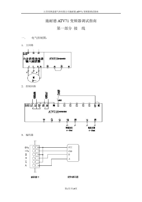
施耐德ATV71变频器调试指南第一部分接线一.电气控制图:1.主回路2.控制回路3.编码器二.端子位置图:1.功率端子分布:ATV71-HD95N4 ATV71-HD95N4(输入电抗器)ATV71-HD45N4/ ATV71-HD55N4 ATV71-HU75N4 2.控制端子位置图:3.编码器卡安装图三.接线注意事项:1.各功率端子和控制端子一定要安装紧固;1.1 动力直流母线端子PO--PA+之间的短接铜片一定要保持紧固;1.2 控制端子的PWR--+24V之间的短接片一定要保持连接,否则变频器将显示状态PRA并且不能正常输出。
1.3 如用AI1+和AI1-做双极性给定,请去掉AI1-和com之间的短接片。
2.请可靠连接各保护地和屏蔽地。
第二部分用中文图形终端编程一.中文图形编程操作终端界面二.菜单结构1.主菜单注:所有的参数调整都在1 变频器菜单中进行,其它的主菜单都是辅助功能。
这些需要在使用中灵活掌握,慢慢积累经验。
2.变频器菜单注:变频器菜单中有关调试主要菜单是1.1 到 1.8 。
我们暂时也仅仅涉及一些主要的菜单和参数。
其它都是辅助菜单,这些需要在使用中灵活掌握,慢慢积累经验。
三.调试的步骤第一步,设置简捷的起停控制设置端子与面板切换功能键(命令菜单):在命令菜单,找到最后一个参数:F4键分配:设置其功能为T/K,即为端子控制(Terminals)与图形终端控制(Kepad)切换。
这样按F4键可以切换用端子控制起停或图形终端控制起停。
端子控制有效时,起停命令来自LI1, LI2的逻辑端子的输入,这时变频器图形终端首行显示的第二个位置显示TERM;图形终端控制激活时,按图形终端上的RUN, STOP,FWD/REV键可以控制变频器的正反转,旋转导航键(浏览鼓轮)改变频率给定这时图形终端首行显示的第二个位置显示HMI。
此设置的目的是为了便于手动试运转。
正常运行时,应采用端子控制。
(常熟工厂为设置)。
ATV71变频器操作说明

ATV71变频器操作说明一启动前的准备首先检查变频器的进线和出现正确连接到变频器,用万用表量进线和出现对地绝缘情况(电机的绝缘在连接到变频器之前应由摇表测过)。
一切正常后,由开关柜送电,量一下进线电压,确保进线电压在变频器允许范围内(380V-480V)且输入平衡。
然后闭合柜门,将刀熔开关打到闭合位置,变频器上电。
此时,柜顶风机运转且向上抽风,变频器操作面板显示正常,显示状态栏显示为RDY.二参数设值首先先记下电机铭牌上的电机额定值,然后按参数表设置参数。
参数设置完后。
进入电机控制菜单执行自整定(此时电机为空载)。
电机自整定完后可以按以下方式控制电机。
三控制每台变频器由三中控制方式:本地控制(操作面板控制启停和调速),远程控制一(电机旁就地箱控制启停),远程控制二(DCS控制启停和调速)。
1.本地操作(1)使用本地操做前要确保变频器处于本地控制模式下,具体信息应在显示面板状态显示栏即第一行第二项显示为“HMI”,第二行显示为“图形终端频率给定”。
若显示为“Term”则需要按下F4键进行切换(若在运行期间改变此参数会导致停车,请在改变此参数前确认)。
(2)显示面板第二行为频率给定,启动变频器前要确认所给频率是否符合要求,若不符可旋转旋钮来增大或减小给定值。
(3)启动变频器,按下面板左下方的RUN按键,变频器开始启动加速,加速到给定频率后,变频器处于运行状态。
启动过程中面板左上角的状态显示栏显示为RDY-ACC-RUN。
(4)停止变频器,按下面板左边的STOP/RESET键,变频器开始启动,直到减速到0HZ后,变频器处于准备状态。
停止过程中面板左上角的状态显示栏显示为RUN-DEC-RDY。
2 远程控制使用远程控制时前要确保变频器处于远程控制时模式下,具体信息应在显示面板状态显示栏即第一行第二项显示为“Term”,第二行显示为“频率给定”。
若显示为“HMI”则需要按下F4键进行切换(若在运行期间改变此参数会导致停车,请在改变此参数前确认)。
施耐德ATV71变频器设置指南
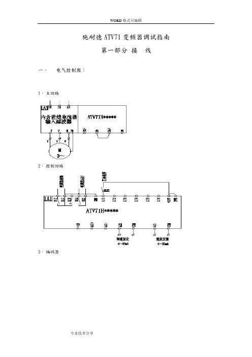
施耐德ATV71变频器调试指南第一部分接线一.电气控制图:1.主回路2.控制回路3.编码器二.端子位置图:1.功率端子分布:ATV71-HD95N4 ATV71-HD95N4(输入电抗器)ATV71-HD45N4/ ATV71-HD55N4 ATV71-HU75N42.控制端子位置图:3.编码器卡安装图三.接线注意事项:1.各功率端子和控制端子一定要安装紧固;1.1 动力直流母线端子PO--PA+之间的短接铜片一定要保持紧固;1.2 控制端子的PWR--+24V之间的短接片一定要保持连接,否则变频器将显示状态PRA 并且不能正常输出。
1.3 如用AI1+和AI1-做双极性给定,请去掉AI1-和com之间的短接片。
2.请可靠连接各保护地和屏蔽地。
第二部分用中文图形终端编程一.中文图形编程操作终端界面二.菜单结构1.主菜单注:所有的参数调整都在 1 变频器菜单中进行,其它的主菜单都是辅助功能。
这些需要在使用中灵活掌握,慢慢积累经验。
2.变频器菜单注:变频器菜单中有关调试主要菜单是1.1 到 1.8 。
我们暂时也仅仅涉及一些主要的菜单和参数。
其它都是辅助菜单,这些需要在使用中灵活掌握,慢慢积累经验。
三.调试的步骤第一步,设置简捷的起停控制设置端子与面板切换功能键(命令菜单):在命令菜单,找到最后一个参数:F4键分配:设置其功能为 T/K,即为端子控制(Terminals)与图形终端控制(Kepad)切换。
这样按F4键可以切换用端子控制起停或图形终端控制起停。
端子控制有效时,起停命令来自LI1, LI2的逻辑端子的输入,这时变频器图形终端首行显示的第二个位置显示TERM;图形终端控制激活时,按图形终端上的RUN, STOP,FWD/REV键可以控制变频器的正反转,旋转导航键(浏览鼓轮)改变频率给定这时图形终端首行显示的第二个位置显示HMI。
此设置的目的是为了便于手动试运转。
正常运行时,应采用端子控制。
(常熟工厂为设置)。
施耐德ATV变频器设置指南
施耐德ATV71变频器调试指南第一部分接线一.电气控制图:1.主回路2.控制回路3.编码器二.端子位置图:1.功率端子分布:ATV71-HD95N4 ATV71-HD95N4(输入电抗器)ATV71-HD45N4/ ATV71-HD55N4 ATV71-HU75N42.控制端子位置图:3.编码器卡安装图三.接线注意事项:1.各功率端子和控制端子一定要安装紧固;1.1 动力直流母线端子PO--PA+之间的短接铜片一定要保持紧固;1.2 控制端子的PWR--+24V之间的短接片一定要保持连接,否则变频器将显示状态PRA并且不能正常输出。
1.3 如用AI1+和AI1-做双极性给定,请去掉AI1-和com之间的短接片。
2.请可靠连接各保护地和屏蔽地。
第二部分用中文图形终端编程一.中文图形编程操作终端界面二.菜单结构1.主菜单注:所有的参数调整都在 1 变频器菜单中进行,其它的主菜单都是辅助功能。
这些需要在使用中灵活掌握,慢慢积累经验。
2.变频器菜单注:变频器菜单中有关调试主要菜单是1.1 到 1.8 。
我们暂时也仅仅涉及一些主要的菜单和参数。
其它都是辅助菜单,这些需要在使用中灵活掌握,慢慢积累经验。
三.调试的步骤第一步,设置简捷的起停控制设置端子与面板切换功能键(命令菜单):在命令菜单,找到最后一个参数:F4键分配:设置其功能为 T/K,即为端子控制(Terminals)与图形终端控制(Kepad)切换。
这样按F4键可以切换用端子控制起停或图形终端控制起停。
端子控制有效时,起停命令来自LI1, LI2的逻辑端子的输入,这时变频器图形终端首行显示的第二个位置显示TERM;图形终端控制激活时,按图形终端上的RUN,STOP,FWD/REV键可以控制变频器的正反转,旋转导航键(浏览鼓轮)改变频率给定这时图形终端首行显示的第二个位置显示HMI。
此设置的目的是为了便于手动试运转。
正常运行时,应采用端子控制。
(常熟工厂为设置)。
施耐德变频器操作说明2012年9月7日
ATV71施耐德变频器操作说明一、图形显示终端按钮功能介绍1,图形显示器;2,功能键F1,F2,F3,F4;3,STOP/RESET(停车/复位)按钮;4,RUN(运行)按钮;5,导航按钮;• 按(ENT): - 保存当前值; 1234657- 进入所选菜单或参数;• 转动CW/CCW:- 增大或减小一个值;- 转到下一行或前一行;- 增大或减小给定值,如果通过终端控制功能被激活;6,用于使电机旋转反向的按钮;7,ESC 按钮:中断一个值、一个参数或一个菜单,返回以前的选择。
※注意:如果通过终端控制功能被激活按钮3、4、5 与6 可用于直接控制变频器。
二、图形显示屏描述1,显示行。
在出厂设置模式下显示:变频器状态:如图中RDY;有效控制通道:如图中Term;频率给定值:如图中+0.00Hz;电机内电流:如图中0A。
2,菜单行。
显示当前菜单或子菜单的名称。
3,菜单、子菜单、参数、值、柱状图等在下拉菜单窗口显示,每个窗口最多显示5行。
导航按钮所选的行或值反白显示。
4,显示分配给键F1至F4的功能,与这四个键上下对应,例如:功能键是动态的,且具有前后关系。
功能键可通过【1.6命令】给这些键分配其他功能。
5,6,二〇一二年九月七日星期五三、变频器状态代码四、设置窗口示例第3 页/共10页五、第一次通电-设置语言和访问等级设置为Chinese。
二〇一二年九月七日星期五第5 页/共10页六、以后通电屏幕显示如下二〇一二年九月七日星期五七、访问参数示例:访问加速斜坡八、变频器菜单的操作方法已经设置过参数的变频器上电时,首先显示变频器的型号,3秒钟以后自动转到【变频器菜单】。
若操作者没有进行操作,10秒后自己转入【DISPLAY显示】,显示内容将根据相关参数设置而改变。
通过按导航按钮或ESC键,用户可以进入【主菜单】。
旋转导航按钮选择【变频器菜单】、【访问等级】、【打开/另存为】、【密码】、【语言】等菜单。
一般来说,我们只需要按导航按钮进入【变频器菜单】即可,其余几种很少用。
施耐德atv-71h变频器说明书
T h e i n f o r m a t i o n p r o v i d e d i n t h i s d o c u m e n t a t i o n c o n t a i n s g e n e r a l d e s c r i p t i o n s a n d /o r t e c h n i c a l c h a r a c t e r i s t i c s o f t h e p e r f o r m a n c e o f t h e p r o d u c t s c o n t a i n e d h e r e i n .T h i s d o c u m e n t a t i o n i s n o t i n t e n d e d a s a s u b s t i t u t e f o r a n d i s n o t t o b e u s e d f o r d e t e r m i n i n g s u i t a b i l i t y o r r e l i a b i l i t y o f t h e s e p r o d u c t s f o r s p e c i f i c u s e r a p p l i c a t i o n s .I t i s t h e d u t y o f a n y s u c h u s e r o r i n t e g r a t o r t o p e r f o r m t h e a p p r o p r i a t e a n d c o m p l e t e r i s k a n a l y s i s , e v a l u a t i o n a n d t e s t i n g o f t h e p r o d u c t s w i t h r e s p e c t t o t h e r e l e v a n t s p e c i f i c a p p l i c a t i o n o r u s e t h e r e o f .N e i t h e r S c h n e i d e r E l e c t r i c I n d u s t r i e s S A S n o r a n y o f i t s a f f i l i a t e s o r s u b s i d i a r i e s s h a l l b e r e s p o n s i b l e o r l i a b l e f o r m i s u s e o f t h e i n f o r m a t i o n c o n t a i n e d h e r e i n .Product data sheetCharacteristicsATV71HD90N4ATV71 90kW 3P 380VAC, 90KW,加强涂层,中文面板,EMC,电抗器主要信息范围Altivar 71产品或组件类型变频器产品特定应用复杂的高功率机械组件名称ATV71电动机功率 kW 90 kW at 380...480 V 3 相电机功率125 hp at 380...480 V 3 相电机电缆长度<= 200 m unshielded cable <= 100 m shielded cable Us 额定电源电压380...480 V (- 15...10 %)网络相数 3 相线路电流166 A 用于 380 V 3 相 90 kW / 125 hp 134 A 用于 480 V 3 相 90 kW / 125 hp EMC 滤波器集成的组装方式带散热片变量加强版视在功率109.3 kVA 在 380 V 3 相 90 kW / 125 hp 预期线路Isc <= 35 kA, 3 相额定输出电流179 A 在 2.5 kHz 460 V 3 相 90 kW / 125 hp 179 A 在 2.5 kHz 380 V 3 相 90 kW / 125 hp 最大瞬变电流295 A 用于 2 s 3 相 90 kW / 125 hp 269 A 用于 60 s 3 相 90 kW / 125 hp 变频器输出频率0.1...500 Hz 标称开关频率 2.5 kHz开关频率2.5...8 kHz 带降额因素2.5...8 kHz 可调非对称电机控制配置文件ENA系统(能量适配系统)的不平衡机器带传感器的通量矢量控制(FVC) (电流矢量)无传感器的通量矢量控制(SFVC) (电压或电流矢量)电压/频率比例 (2或5点)极化方式无阻抗 for Modbus补充信息产品定义异步电机同步电机电源电压限制323...528 V供电频率50...60 Hz (- 5...5 %)网络频率限制47.5...63 Hz速度范围1...50 for synchronous motor in open-loop mode, without speed feedback 1...1000 for asynchronous motor in closed-loop mode with encoder feedback 1...100 for asynchronous motor in open-loop mode, without speed feedback 速度精度+/- 10 % 标称滑距 用于 0.2 Tn 至 Tn 转矩变化 不带速度反馈+/- 0.01 % 标称速度 用于 0.2 Tn 至 Tn 转矩变化 处于带编码器反馈的闭环模式中扭矩精度+/- 5 % 处于带编码器反馈的闭环模式中+/- 15 % 处于开环模式下, 无速度反馈瞬时过转矩220 % 标称电机转矩的 +/- 10 % 用于 2 s170 % 标称电机转矩的 +/- 10 % 用于 60 s every 10 minutes 制动力矩30 % 不带制动电阻器< 150 % 带有制动或提升电阻器同步电机控制配置模式矢量控制无速度反馈调节回路PI监控电机滑差补偿可调自动 无论负载情况不可用电压/频率比(2 或 5 点)可抑制就地信号 1 LED 红 状态 设备电压输出电压<= 电源电压隔离电源与控制之间的电路电缆类型不带安装套件: 1-绞股 IEC 电缆 在 45 °C, 铜 90 °C XLPE/EPR不带安装套件: 1-绞股 IEC 电缆 在 45 °C, 铜 70 °C PVC带有一个 IP21 或 IP31 套件: 3-绞股 IEC 电缆 在 40 °C, 铜 70 °C PVCWith a NEMA Type1 kit: 3-strand UL 508 cable at 40 °C, copper 75 °C PVC电气连接PC/-, PO, PA/+ 端子 2 x 100 mm²PA, PB 端子 60 mm²L1/R, L2/S, L3/T, U/T1, V/T2, W/T3 端子 2 x 100 mm²AI1-/AI1+, AI2, AO1, R1A, R1B, R1C, R2A, R2B, LI1...LI6, PWR 端子 2.5 mm² /AWG 14紧固转距PC/-, PO, PA/+ 41 N.m / 360 lb.内部PA, PB 12 N.m / 106 lb.内部L1/R, L2/S, L3/T, U/T1, V/T2, W/T3 24 N.m / 212 lb.内部AI1-/AI1+, AI2, AO1, R1A, R1B, R1C, R2A, R2B, LI1...LI6, PWR 0.6 N.m电源内部电源, 24 V 直流, 电压限制 21...27 V, <= 200 mA 用于 过载和短路保护内部电源 用于参考电位计 (1 至 10 kOhm), 10.5 V 直流 +/- 5 %, <= 10 mA 用于 过载和短路保护模拟量输入数量2模拟量输入类型AI2 软件-可配置电压 0...10 V 直流, 输入电压 24 V 最大, 阻抗 30000 Ohm, 分辨率11 位AI2 软件-可配置电流 0...20 mA, 阻抗 242 Ohm, 分辨率 11 位AI1-/Al1+ 双极差分电压 +/- 10 V 直流, 输入电压 24 V 最大, 分辨率 11位+符号位采样期间LI6 (如果配置为逻辑输入的话) 2 ms, +/- 0.5 ms 用于 Discrete 输入LI1...LI5 2 ms, +/- 0.5 ms 用于 Discrete 输入Al2 2 ms, +/- 0.5 ms 用于 模拟 输入AI1-/Al1+ 2 ms, +/- 0.5 ms 用于 模拟 输入反应时间R2A, R2B 7 ms, 容限 +/- 0.5 ms 用于 离散量 输出R1A, R1B, R1C 7 ms, 容限 +/- 0.5 ms 用于 离散量 输出AO1 2 ms, 容限 +/- 0.5 ms 用于 模拟 输出<= 100 ms 在 STO (安全转矩关闭) 内精度AO1 +/- 1 % 用于60 °C的温度变动AI2 +/- 0.6 % 用于60 °C的温度变动AI1-/Al1+ +/- 0.6 % 用于60 °C的温度变动线性度误差AO1 +/- 0.2 %AI1-/Al1+, AI2 最大值 +/- 0.15 %模拟量输出数量1模拟输出 型号AO1 软件-可配置电压 0...10 V 直流, 阻抗 470 Ohm, 分辨率 10 位AO1 软件-可配置电流 0...20 mA, 阻抗 500 Ohm, 分辨率 10 位AO1 软件-可配置逻辑输出 10 V <= 20 mA离散量输出数量2输出型式R2A, R2B 可配置的继电器逻辑 NO, 电气寿命 100000 cyclesR1A, R1B, R1C 可配置的继电器逻辑 NO/NC, 电气寿命 100000 cycles最小开关电流可配置的继电器逻辑 3 mA at 24 V 直流最大开关电流R1, R2 在…上 电阻性 负载, 5 A 在 30 V 直流, cos phi = 1,R1, R2 在…上 电阻性 负载, 5 A 在 250 V AC, cos phi = 1,R1, R2 在…上 电感式 负载, 2 A 在 30 V 直流, cos phi = 0.4,R1, R2 在…上 电感式 负载, 2 A 在 250 V AC, cos phi = 0.4,离散量输入数量7离散量输入类型PWR: 安全输入 24 V 直流, impedance: 1500 欧姆 符合 ISO 13849-1 d 级LI6: 开关可配置 PTC 探头 0...6, impedance: 1500 欧姆LI6: 开关-可配置 24 V 直流 有 1 级 PLC, impedance: 3500 欧姆LI1...LI5: 可编程 24 V 直流 有 1 级 PLC, impedance: 3500 欧姆离散量输入逻辑LI6 (如果配置为逻辑输入的话) 正逻辑(源), < 5 V (状态 0), > 11 V (状态 0)LI6 (如果配置为逻辑输入的话) 负逻辑 (阱), > 16 V (状态 0), < 10 V (状态 0)LI1...LI5 正逻辑(源), < 5 V (状态 0), > 11 V (状态 0)LI1...LI5 负逻辑 (阱), > 16 V (状态 0), < 10 V (状态 0)加速和减速倾斜超出刹车能力时的坡道自适应,采用电阻从 0.01 至 9000 s 独立线性可调S, U 或定制的制动至停止采用直流注入保护类型马达 热保护马达 拆卸电源马达 电机断相驱动 热保护驱动 电机各相线之间短路驱动 直流总线过压驱动 过热保护驱动 输出相线和接地之间的过流驱动 总线供电欠压驱动 线路电源过压驱动 输入断相驱动 控制电路上制动驱动 防止输入相位丢失驱动 防止超出限制速度绝缘电阻> 1 mOhm 在 接地 1 分钟 500 V 直流频率分辨率显示单元 0.1 Hz模拟量输入 0.024/50 Hz通讯端口协议CANopenModbus连接器类型RJ45的针型SUB-D 9 for CANopen1 RJ45 for Modbus 在终端上1 RJ45 for Modbus 在前脸物理接口 2 线 RS485 for Modbus传输帧RTU 用于 Modbus传输率9600 bps, 19200 bps for Modbus 在前脸4800 bps, 9600 bps, 19200 bps, 38.4 Kbps for Modbus 在终端上20 kbps, 50 kbps, 125 kbps, 250 kbps, 500 kbps, 1 Mbps 用于 CANopen 数据格式8 位, 奇偶 或无可配置的校验 for Modbus 在终端上8 位, 1 停止, 偶校验 for Modbus 在前脸地址数 1...247 for Modbus1...127 for CANopen访问方法从 for CANopen标志CE操作位置垂直方向 +/- 10°高度920 mm深度377 mm宽度320 mm产品重量60 kg选项卡Profibus DP V1 通信卡Profibus DP 通信卡头顶的起重机卡Modbus/Uni-Telway 通信卡Modbus TCP 通信卡Modbus Plus 通信卡编码器的接口卡Interbus-S 通信卡I/O 扩展卡Fipio 通信卡Ethernet/IP 通信卡DeviceNet 通信卡控制器内可编程卡CC-Link 通信卡环境噪音等级60.5 dB 符合 86/188/EEC介电强度5092 V 直流 控制和电源接线端之间3535 V 直流 接地和电源接线端之间电磁兼容性电压下降与断路抑制测试 conforming to IEC 61000-4-11传播射频电磁场抑制性测试 conforming to IEC 61000-4-3 级别 3静电放电抑制测试 conforming to IEC 61000-4-2 级别 3快速电瞬流/突变抑制测试 conforming to IEC 61000-4-4 级别 4传导射频抑制测试 conforming to IEC 61000-4-6 级别 31.2/50 µs - 8/20 µs surge immunity test conforming to IEC 61000-4-5 level 3标准EN 55011 A 类第 2 组EN 61800-3 环境 1 级别 C3EN 61800-3 环境 2 级别 C3EN/IEC 61800-3EN/IEC 61800-5-1IEC 60721-3-3 第 3C2 类UL 类型 1产品认证CSAC-TickGOSTNOM 117UL污染程度 3 符合 UL 8402 符合 EN/IEC 61800-5-1IP 保护等级IP54 对下面的部件 conforming to EN/IEC 61800-5-1IP54 对下面的部件 conforming to EN/IEC 60529IP41 在上方部件 conforming to EN/IEC 61800-5-1IP41 在上方部件 conforming to EN/IEC 60529IP30 在前面板 conforming to EN/IEC 61800-5-1IP30 在前面板 conforming to EN/IEC 60529IP30 对侧面部件 conforming to EN/IEC 61800-5-1IP30 对侧面部件 conforming to EN/IEC 60529IP00 符合 EN/IEC 61800-5-1IP00 符合 EN/IEC 60529抗振动波峰至波峰 1.5 mm (f = 3...10 Hz) 符合 EN/IEC 60068-2-60.6 gn (f = 10...200 Hz) 符合 EN/IEC 60068-2-6抗冲击7 gn 用于 11 ms conforming to EN/IEC 60068-2-27相对湿度 5...95 % 无滴水 conforming to IEC 60068-2-35...95 % 无冷凝 conforming to IEC 60068-2-3工作环境温度-10...50 °C 无降容存储环境温度-25...70 °C海拔高度1000...3000 m 电流降额 1%/100m<= 1000 m 无降容。
施耐德ATV71变频器设置指南
施耐德ATV71变频器调试指北之阳早格格创做第一部分接线一.电气统造图:1.主回路2.统造回路3.编码器二.端子位子图:1.功率端子分散:ATV71-HD95N4 ATV71-HD95N4(输进电抗器)ATV71-HD45N4/ ATV71-HD55N4 ATV71-HU75N42.统造端子位子图:3.编码器卡拆置图三.接线注意事项:1.各功率端子战统造端子一定要拆置紧固;1.1 能源曲流母线端子PO--PA+之间的短接铜片一定要脆持紧固;1.2 统造端子的PWR--+24V之间的短接片一定要脆持对接,可则变频器将隐现状态PRA而且不克不迭仄常输出. 1.3 如用AI1+战AI1-干单极性给定,请去掉AI1-战com之间的短接片.2.请稳当对接各呵护天战屏蔽天.第二部分用华文图形末端编程一.华文图形编程支配末端界里二.菜单结构1.主菜单注:所有的参数安排皆正在1 变频器菜单中举止,其余的主菜单皆是辅帮功能.那些需要正在使用中机动掌握,缓缓聚集体味.2.变频器菜单注:变频器菜单中有关调试主要菜单是1.1 到1.8 .咱们姑且也只是波及一些主要的菜单战参数.其余皆是辅帮菜单,那些需要正在使用中机动掌握,缓缓聚集体味.三.调试的步调第一步,树坐简便的起停统造树坐端子与里板切换功能键(下令菜单):正在下令菜单,找到末尾一个参数:F4键调配:树坐其功能为T/K,即为端子统造(Terminals)与图形末端统造(Kepad)切换.那样按F4键不妨切换用端子统造起停或者图形末端统造起停.端子统造灵验时,起停下令去自LI1, LI2的逻辑端子的输进,那时变频器图形末端尾止隐现的第二个位子隐现TERM;图形末端统造激活时,按图形末端上的RUN, STOP,FWD/REV键不妨统造变频器的正反转,转化导航键(欣赏饱轮)改变频次给定那时图形末端尾止隐现的第二个位子隐现HMI.此树坐的脚段是为了便于脚动试运止.仄常运止时,应采与端子统造.(常生工厂为树坐).第二步,树坐电机的关环磁通矢量统造办法1.电机铭牌参数的输进与参数劣化(1.4电机统造菜单) :正在1.4 电机统造菜单中,咱们需要输进以下电机铭牌参数,脚段是为了让变频器辨别电机的电气指标,以便真止最劣统造.电机参数的不当输进会引起输出的不宁静,引导电机的剧烈振荡,特殊收热及变频器等的益坏.电机额定功率:电机铭牌上标定的确定接法,额定频次下的额定功率(如11KW, 4KW);电机额定电压:电机铭牌上标定的确定接法,额定频次对于应的额定电压(如380V);电机额定电流:电机铭牌上标定的确定接法下的额定电流(如23.5A, 8.8A);电机额定频次:电机铭牌上标定的确定接法,额定电压对于应的额定频次(如50Hz);电机额定速度:电机铭牌上标定的对于应于额定频次下的额定转速(如1450rpm等);最大输出频次:应用中大概运止的最下输出频次(如100 Hz, 65Hz).注意此值决断其余菜单中的频次上限.上述参数设定后,变频器将不妨精确辨别战统造电机.为了真止最好统造,提议真止电机参数自整定.参数自整定:设为哀供自整定,变频器将背电机注进一定序次的电压战电流.不妨正在支配末端上瞅到运止电流正在变更,但是电机不会转化.变频器的状态隐现为“TUN”,约二秒钟后,变频器状态隐现回复为“rdy”,自整定参数的真质形成已完毕,表示自整定完毕,电机适配历程中断.2.编码器树坐战查看(1.4电机统造菜单)2.1 正在1.4 电机统造菜单中,先树坐编码器的参数:脉冲旗号典型:编码器的输进旗号典型(如AB代表单端输进,AABB代表AA-BB-单端输进)脉冲数量:编码器的每圈线数(如600,1024等)2.2收端查看编码器反馈是可仄常.按F4键切换到当天图形末端统造,按RUN键起动,转化导航轮达到一定的运止频次.那是电机应仄常运止,瞅察其运止电流正在仄常范畴之内.加进1.2监视菜单,瞅察给定频次,输出频次战丈量输出频次三者是可普遍.那里,给定频次即下令频次,输出频次为本质输出电机频次,丈量输出频次为编码器反馈的电机转速合算的频次值.输出频次战丈量输出频次值的正背代表转背或者输出相序.丈量输出频次与输出频次二个值正在数值上战标记上基原上该当是真足普遍,如果标记普遍,标明编码器接线精确,如果差异,标明编码器丈量转背与变频器本质输出相序纷歧致,该当接换AB线或者变更变频器输出相序.如果数值纷歧致,应查看编码器参数树坐战接线、屏蔽等的稳当性.最后保证丈量输出频次与输出频次的普遍性.2.3编码器查看.正在1.4 电机统造菜单中.树坐参数编码器查看的真质为YES,而后起动变频器并将运止频次树坐到15Hz以上,如果成功,变频器的输出电流,频次,丈量输出频次该当非常宁静,参数编码器查看的真质将自动形成已完毕.可则,若变频器的输出电流很大,变频器的状态隐现为CLI,电机振荡战噪声很剧烈,应坐时停机并应查看编码器的接线战树坐到通过为止.3.树坐变频器为关环磁通矢量统造办法(1.4 电机统造菜单)正在1.4 电机统造菜单中,树坐参数电机统造典型为FVC(关环磁通矢量统造).第三步,举止其余需要的树坐战安排1.树坐造动电阻灵验(1.7 应用功能菜单).正在1.7 应用功能菜单中,找到斜坡功能,其末尾一个参数为减速斜坡自符合,即过压得速呵护功能,将其设为无,即树坐造动电阻灵验.2.设定面动功能(1.7应用功能菜单).正在1.7 应用功能菜单中,找到寸动功能,树坐参数寸动为LIx(如LI3),即树坐LIx为面动功能,其余树坐参数寸动频次为需要的值.3.调配障碍复位端子(1.8障碍管造菜单)正在1.8障碍管造菜单中,找到障碍复位子菜单,将参数障碍复位的树坐改为LIy(如LI4),即树坐LIy为障碍复位端.4.设定二线造统造典型(1.5 输进输出树坐菜单)正在1.5 输进输出树坐菜单中,将参数2线统造的树坐由边沿触收改为0/1电仄,以预防变频器果上电起动逻辑引导锁定.5.树坐频次上下限及加减速时间(1.3 树坐菜单)正在1.3 树坐菜单中,树坐一些需要的参数如:加速时间从0到电机额定频次的加速斜坡时间;减速时间从电机额定频次到0的减速斜坡时间;矮速频次最矮运止频次,对于应于模拟量输进的最小值;下速频次最下运止频次,对于应于模拟量输进的最大值.至此,变频器的树坐基原完毕.四.变频器状态的监视正在对于变频器举止调试的历程中,注意瞅察变频器的状态对于赶快精确天树坐,调试等具备很大的帮闲效率.底下介绍几种真用的变频器变量监视要领.要领一,利用图形支配末端的尾止隐现ATV71的图形末端的尾止隐现正在所有状态皆是牢固存留的.其中,①隐现变频器的状态,除障碍代码中,一共大概有下列状态隐现:ACC: 依照斜坡加速;DEC: 依照斜坡减速;RUN: 仄常稳速运止;RDY: 便绪,准备好;DCB: 曲流注进造动举止中;CLI: 电流限幅,如果出现那种情况,证明树坐有不当之处,应查看参数树坐;OBR: 造动电阻为激活,查看参数树坐;NLP: 无主电源,PO与PA+之间对接短好;NST: 锁定输出;端子统造时按图形末端上的STOP键,或者自由停车端子激活,或者二线统造典型树坐为边沿触收,但是上电前已从端子给起动旗号;PRA: 断电功能灵验,PWR与+24V断启;TUN: 自整定举止中.根据目前树坐,其余状态隐现不可能存留.如出现障碍代码,请正在依照变频器脚册中查找办理办法.②统造下令源,指目前的起停正反转指令的统造源,根据目前树坐,有二种大概:Term:端子统造HMI:图形支配末端统造③,④二个不妨设定的变量,出厂设定为给定频次战电机电流,不妨正在主菜单中的6 监视树坐中采用体贴的任性二个监视变量:正在6 监视树坐主菜单中的子菜单6.1参数止采用中,选中任性二个目前最体贴的二个变量,如输出频次,电机电流,电机转矩,电网电压等.要领二:利用图形支配末端的主隐现绘里:主隐现绘里不妨采用如上三种办法:1.数值隐现:那种办法不妨采用共时隐现1个或者2个变量,字体较大,简单瞅得到;2.条线图(棒状图)隐现:那种办法不妨采用共时隐现1个或者2个变量,比较好瞅(图形隐现);3.列表隐现:那种办法不妨采用共时隐现多达5个变量,疑息量大.主隐现绘里的设定正在6 监视树坐主菜单中的子菜单6.2 隐现屏幕典型树坐中设定:正在参数隐现典型中采用隐现的典型,正在参数采用参数中采用要隐现的参数,数目与决于隐现典型.要领三:利用1.2 监视菜单正在监视菜单中不妨随时用欣赏键瞅察变频器的任性状态值(睹编程脚册中1.2监视菜单).那里值得一提的是,正在1.2 监视菜单中不妨随时瞅察变频器统造端子状态战设定(含逻辑输进,逻辑输出,模拟量输进,模拟量输出),睹1.2 监视菜单中的输进输出映象.逻辑输进映象战设定:模拟输进映象战设定:逻辑输出映象战设定:模拟输出映象战设定:第三部分用集成隐现末端设定一、集成图形末端与菜单结构及参数建改要领:1.集成图形末端示企图2.菜单结构集成图形末端的菜单战参数隐现办法为4位7段码英文简写代码:注:变频器菜单中有关调试主假如利用Set, drC, I-O, CtL, FUn, FLt 等.咱们姑且也只是波及一些主要的菜单战参数.其余皆是辅帮菜单,那些需要正在使用中机动掌握,缓缓聚集体味.3.参数建改举例二、调试的步调第一步,树坐电机的关环磁通矢量统造办法1.电机铭牌参数的输进与参数劣化(drC-电机统造菜单) :正在drC-电机统造菜单中,咱们需要输进以下电机铭牌参数,脚段是为了让变频器辨别电机的电气指标,以便真止最劣统造.电机参数的不当输进会引起输出的不宁静,引导电机的剧烈振荡,特殊收热及变频器等的益坏.nPr:电机铭牌上标定的确定接法,额定频次下的额定功率(如11KW, 4KW);UnS:电机铭牌上标定的确定接法,额定频次对于应的额定电压(如380V);nCr:电机铭牌上标定的确定接法下的额定电流(如23.5A, 8.8A);FrS:电机铭牌上标定的确定接法,额定电压对于应的额定频次(如50Hz);nSP:电机铭牌上标定的对于应于额定频次下的额定转速(如1450rpm等);tFr:应用中大概运止的最下输出频次(如100 Hz, 65Hz).注意此值决断其余菜单中的频次上限.上述参数设定后,变频器将不妨精确辨别战统造电机.为了真止最好统造,提议真止电机参数自整定.tUn:nO yES,变频器将背电机注进一定序次的电压战电流,但是电机不会转化.约二秒钟后,tUn的真质自动形成dOnE,表示自整定完毕,电机适配历程中断.2.编码器树坐战查看(drC- 电机统造菜单)2.1 正在drC-电机统造菜单中,先树坐编码器的参数:EnS:编码器的输进旗号典型(如AB代表单端输进,AABB代表AA-BB-单端输进)PGI:脉冲数量,编码器的每圈线数(如600,1024等)2.2收端查看编码器反馈是可仄常.将LI1端子与24V短接,起动变频器.正在Set- 树坐菜单中,树坐参数LSP(矮速频次)为某值,那时电机应依照LSP树坐的频次仄常运止,瞅察电机运止是可宁静.加进SUP- 监视菜单,瞅察给定频次FrH,输出频次rFR战丈量输出频次MMF三者是可普遍.那里,给定频次(FrH)即下令频次(正在不模拟量旗号的情况下,等于LSP确定的频次),输出频次(rFr)为本质输出电机频次,丈量输出频次(MMF)为编码器反馈的电机转速合算的频次值.输出频次(rFr)战丈量输出频次值(MMF)的正背代表转背或者输出相序.丈量输出频次(MMF)与输出频次(rFr)二个值正在数值上战标记上基原上该当是真足普遍,如果标记普遍,标明编码器接线精确,如果差异,标明编码器丈量转背与变频器本质输出相序纷歧致,该当接换AB线或者变更变频器输出相序.如果数值纷歧致,应查看编码器参数树坐战接线、屏蔽等的稳当性.最后保证丈量输出频次与输出频次的普遍性.2.3编码器查看.正在drC- 电机统造菜单中.树坐ENC(编码器查看)的真质为YES,而后起动变频器并将给定频次(LSP)树坐到15Hz以上,如果成功,编码器查看(ENC)的真质将自动形成dOnE,表示编码器查看通过.可则若电机振荡战噪声很剧烈,应坐时停机并应查看编码器的接线战树坐到通过为止.3.树坐变频器为关环磁通矢量统造办法(drC- 电机统造菜单)正在drC- 菜单中,树坐参数Ctt(电机统造典型) 为FVC (关环磁通矢量统造).第三步,举止其余需要的树坐战安排1.树坐造动电阻灵验(FUn- 应用功能菜单).正在FUn- 应用功能菜单中,找到rPC- (斜坡树坐)子菜单,其末尾一个参数为brA(减速斜坡自符合) ,即过压得速呵护功能,将其设为nO,即树坐造动电阻灵验.2.设定面动功能(FUn- 应用功能菜单).正在FUn- 应用功能菜单中,找到JOG-(寸动),树坐参数JOG为LIx(如LI3),即树坐LIx为面动功能,其余树坐参数JGF(寸动频次)为符合的值.3.调配障碍复位端子(FLt-障碍管造菜单)正在FLt- 障碍管造菜单中,找到rSF- 障碍复位子菜单,将参数rSF-障碍复位的树坐改为LIy(如LI4),即树坐LIy为障碍复位端.4.设定二线造统造典型(I-O- 输进输出树坐菜单)正在I-O- 输进输出树坐菜单中,将参数tCt的树坐由trn改为LEL,以预防变频器果上电起动逻辑引导锁定.5.树坐频次上下限及加减速时间(Set-树坐菜单)正在Set- 树坐菜单中,树坐一些需要的参数如:ACC(加速时间) 从0到电机额定频次的加速斜坡时间;DEC(减速时间) 从电机额定频次到0的减速斜坡时间;LSP(矮速频次) 最矮运止频次,对于应于模拟量输进的最小值;HSP(下速频次) 最下运止频次,对于应于模拟量输进的最大值.至此,变频器的树坐基原完毕.四、变频器状态的监视正在对于变频器举止调试的历程中,注意瞅察变频器的状态对于赶快精确天树坐,调试等具备很大的帮闲效率.底下介绍几种真用的变频器状态监视要领.要领一,利用集成末端上的状态隐现加进SUP-监视菜单上后最先隐现的是变频器状态.除障碍代码中,一共大概有下列状态隐现:ACC: 依照斜坡加速;DEC: 依照斜坡减速;RUN: 仄常稳速运止;RDY: 便绪,准备好;DCB: 曲流注进造动举止中;CLI: 电流限幅,如果出现那种情况,证明树坐有不当之处,应查看参数树坐;OBR: 造动电阻为激活,查看参数树坐;NLP: 无主电源,PO与PA+之间对接短好;NST: 锁定输出;端子统造时按图形末端上的STOP键,或者自由停车端子激活,或者二线统造典型树坐为边沿触收,但是上电前已从端子给起动旗号;PRA: 断电功能灵验,PWR与+24V断启;TUN: 自整定举止中.根据目前树坐,其余状态隐现不可能存留.如出现障碍代码,请正在依照变频器脚册中查找办理办法.要领二:利用SUP-监视菜单监视变频器里里状态变量利用SUP-菜单中不妨读与给定频次,输出频次/电流/转矩/功率等本质运奇迹态变量,以便瞅察变频战背载运止是可仄常.注意:原表中的ULn所示的主电源电压并不是从电源侧检测的真真的电网电压,而是从曲流母线合算(=Udc/1.414),故当电机处于造动收电状态时,此监视值有大概550V安排.要领三:利用SUP-监视菜单真施检测变频器统造端子的状态战功能调配.第五部分参数表(一) 用图形编程末端设定哀供自整定完毕No YES dOnESVCU FVC有无nO LI3nO LI4边沿触收0/1电仄(二) 用集成编程末端设定YES dOnENo YES dOnESVCU FVCYES nOnO LI3nO LI4trn LEL。
- 1、下载文档前请自行甄别文档内容的完整性,平台不提供额外的编辑、内容补充、找答案等附加服务。
- 2、"仅部分预览"的文档,不可在线预览部分如存在完整性等问题,可反馈申请退款(可完整预览的文档不适用该条件!)。
- 3、如文档侵犯您的权益,请联系客服反馈,我们会尽快为您处理(人工客服工作时间:9:00-18:30)。
警告
不正确的变频器操作
• 如果变频器长时间没有通电,则其电解电容器的性能将会下降。 • 如果变频器将在很长一段时间内不使用,应每两年将变频器至少通电 5 小时,以恢复 电容器的性能,然后检查其工作情况。建议不要将变频器与线电压直接连接,应使用 可调的 AC 电压源逐渐加压。 不按照使用说明会导致设备损坏。
v 按照此文件中的说明安装变频器 v 安装任意一个内部与外部选件
b 4 给变频器接线
v v v v 连接电机,确保电压一致 连接控制线路 连接速度给定 在确保电源关闭之后连接电源
编程 v 1 请参考编程手册
5
初步建议
吊运与贮存
为了在安装之前保护变频器,吊运和贮存时应将其放在原始包装内,并确保周围条件能够满足要求。
Altivar 71 异步电机变频器
安装手册
0.37 KW (0.5 HP)...45 KW (60 HP) / 200 - 240V 0.75 KW (1 HP)...75 KW (100 HP) / 380 - 480V
目录
开始之前 ____________________________________________________________________________________________________ 4 变频器安装步骤_______________________________________________________________________________________________ 5 初步建议 ____________________________________________________________________________________________________ 6 变频器额定值 ________________________________________________________________________________________________ 7 安装与温度条件 _____________________________________________________________________________________________ 10 壁挂式或落地式安装的柜子_____________________________________________________________________________________ 12 安装图形显示终端 ____________________________________________________________________________________________ 14 充电 LED 的位置 _____________________________________________________________________________________________ 15 安装选项卡 _________________________________________________________________________________________________ 16 安装 EMC ( 电磁兼容 ) 板 ______________________________________________________________________________________ 18 接线建议 ___________________________________________________________________________________________________ 19 功率端子 ___________________________________________________________________________________________________ 21 控制端子 ___________________________________________________________________________________________________ 23 可选端子 ___________________________________________________________________________________________________ 25 连线图 _____________________________________________________________________________________________________ 30 在 IT ( 隔离的或阻抗接地中点 ) 系统中运行 ________________________________________________________________________ 39 电磁兼容性 , 连线 ____________________________________________________________________________________________ 40
3 相电源电压: 200…240 V 50/60 Hz
3 相电机 200...240 V 电机 铭牌上指示的 功率 (1) kW 0.37 0.75 1.5 2.2 3 4 5.5 7.5 11 15 18.5 22 30 37 45 HP 0.5 1 2 3 5 7.5 10 15 20 25 30 40 50 60 线路电源 ( 输入 ) 最大线电流 (2) 在 200 V 时 在 240 V 时 A 3.5 6.1 11.3 15 19.3 25.8 35 45 53.3 71.7 77 88 124 141 167 A 3.1 5.3 9.6 12.8 16.4 22.9 30.8 39.4 45.8 61.6 69 80 110 127 147 kA 5 5 5 5 5 5 22 22 22 22 22 22 22 22 22 kVA 1.3 2.2 4 5.3 6.8 9.2 12.4 15.9 18.8 25.1 27.7 32 42.4 51 65 A 9.6 9.6 9.6 9.6 9.6 9.6 23.4 23.4 93.6 93.6 100 100 250 250 250 A 3 4.8 8 11 13.7 17.5 27.5 33 54 66 75 88 120 144 176 预期最大线 视在功率 电流 Isc 变频器 ( 输出 ) 最大启动电 额定电流 最高瞬时电流 (1) In (1) 流 (3) 60 s 时 A 4.5 7.2 12 16.5 20.6 26.3 41.3 49.5 81 99 112 132 180 216 264 2s时 A 4.9 7.9 13.2 18.1 22.6 28.8 45.3 54.5 89.1 109 124 145 198 238 290 ATV71H037M3(4) ATV71H075M3(4) ATV71HU15M3(4) ATV71HU22M3(4) ATV71HU30M3(4) ATV71HU40M3(4) ATV71HU55M3(4) ATV71HU75M3(4) ATV71HD11M3X(4) ATV71HD15M3X(4) ATV71HD18M3X ATV71HD22M3X ATV71HD30M3X ATV71HD37M3X ATV71HD45M3X Altivar 71 型号 (5)
警告
损坏的设备
不要操作或安装任何看起来已损坏的变频器。 不按照使用说明会导致设备损坏。
安装时吊运
45° 最大
ALTIVAR 71 变频器,一直到 ATV71HD15M3X 与 ATV71HD18N4,可以不用搬运设备就可 从包装中取出并进行安装。 大型变频器安装时必须使用吊钩。因此,为其专门配备了吊耳。 起吊过程中必须注意下面描述的预防措施。
预防措施
阅读并了解 “编程手册”中的使用说明。
警告
线电压不一致
在加电与配置变频器之前,应确保线电压与变频器铭牌上所示的电源电压范围适应。如果线电压与电源电压范围不一致, 就有可能损坏变频器。 不按照使用说明会导致设备损坏。
DANGER 危险
Hale Waihona Puke 无意的设备操作• 在接通与配置 Altivar 71 之前,为了防止意外起动,应检查并确认 PWR ( 断电 ) 输入无效 ( 状态 0)。 • 在接通 Altivar 71 之前或在退出配置菜单时, 因运行命令能使电机立即起动, 故应检查并确认分配给运行命令的输入为无 效 ( 状态 0)。 不按照使用说明会导致死亡或严重伤害。
如果人员安全方面要求禁止没有必要或意料之外的起动,则由 Altivar 71 的断电 (Power Removal) 功能实现电子锁定。 此功能需要使用符合标准 EN 954-1 第 3 类的连接图以及依照 IEC/EN 61508 的安全完整性等级 2。 断电功能比任何运行命令都具有优先权。
6
变频器额定值
4
变频器安装步骤
安装 b 1 变频器交付
v 检查并确认印在标签上的目录编号与定购单上的相同 v 去除 Altivar 的包装,检查在运输过程中有无损坏
b 2 检查线电压
执行步骤 1 至 4 时 必须关闭电源。
v 检查并确认线电压与变频器的电压范围适应 ( 见第 7 页与第 8 页 )
b 3 安装变频器
单相电源电压: 200...240 V 50/60 Hz
3 相电机 200...240 V 电机 铭牌上指示的 功率 (1) kW 0.37 0.75 1.5 2.2 3 4 5.5 HP 0.5 1 2 3 5 7.5 线路电源 ( 输入 ) 最大线电流 (2) 在 200 V 时 在 240 V 时 A 6.9 12 18.2 25.9 25.9 34.9 47.3 A 5.8 9.9 15.7 22.1 22 29.9 40.1 kA 5 5 5 5 5 22 22 kVA 1.4 2.4 3.7 5.3 5.3 7 9.5 A 9.6 9.6 9.6 9.6 9.6 9.6 23.4 A 3 4.8 8 11.0 13.7 17.5 27.5 预期最大线 视在功率 电流 Isc 变频器 ( 输出 ) 最大启动电 额定电流 最高瞬时电流 (1) In (1) 流 (3) 60 s 时 A 4.5 7.2 12 16.5 20.6 26.3 41.3 2s时 A 4.9 7.9 13.2 18.1 22.6 28.8 45.3 ATV71H075M3(4) ATV71HU15M3(4) ATV71HU22M3(4) ATV71HU30M3(4) ATV71HU40M3(4)(6) ATV71HU55M3(4)(6) ATV71HU75M3(4)(6) Altivar 71 型号 (5)