trace32仿真器使用教程+
TRACE32 iAMP 双核调试应用说明书

Application Note for iAMP Debugging Release 09.2023TRACE32 Online HelpTRACE32 DirectoryTRACE32 IndexTRACE32 Documents ...................................................................................................................... Multicore Debugging ..................................................................................................................... Application Note for iAMP Debugging . (1)SMP, iAMP or AMP? (3)iAMP Setup (7)Example iAMP Setup10Version 09-Oct-2023 11-Nov-2021New manual.SMP, iAMP or AMP?TRACE32 offers various configuration possibilities for debugging multi-core target systems. This chapter explains the basic differences between:•SMP (Symmetrical MultiProcessig)•iAMP (integrated Asymmetrical MultiProcessing)•AMP (Asymmetrical MultiProcessig)This application note focuses on iAMP. It gives you a basic overview of the iAMP concept and helps you to choose the right configuration for your setup. For further details about iAMP and the commands used here, you can also see the “General Reference Guide” (general_ref_<x>.pdf) or contact**********************.If you want to create a new TRACE32 setup for any multicore system, one of the very first decisions you have to make is “AMP or SMP or iAMP?”. In some cases, only one of the possibilities is supported by TRACE32, for example: if you have several cores of different architectures (like one Arm core, one Xtensa core and one RISC-V core), then AMP is the only possible option. But in many cases, you have a choice.Let’s first take a look at the key properties of the three concepts:•All cores have the same instruction set.•All cores use the same instance of an OS (when not bare-metal and unless you are using a hypervisor (“Hypervisor Debugging User Guide” (hypervisor_user.pdf)).•All cores use the same memory model and same address translations (unless you are using a hypervisor).•All cores share the same physical and logical address space.•All cores share the same debug symbols (typically the same elf file).•All cores are debugged from a single TRACE32 PowerView instance. Y ou can have up to 1024cores.•TRACE32 starts and stops all cores simultaneously (even though you can temporarily single out one core for independent start/stop).iAMP (integrated asymmetrical multiprocessing):•All cores have the same instruction set.•There are typically multiple OS instances (if not bare metal).•There is just one global physical address space but each OS maintains its own set of virtual address spaces.•All cores are debugged from a single TRACE32 PowerView GUI. The number of cores is limited just by the core architecture used and can be very high.•TRACE32 allows to group cores logically into machines; this grouping depends on the logical structure of the system under debug - each machine consists of one or more cores. Up to30machines are possible.•Each machine has its own OS instance (if not bare metal).•Each machine has its own memory model, address translations and debug symbols.•TRACE32 starts and stops all cores simultaneously (even though you can temporarily single out one core for independent start/stop).•AMP can bundle single cores, as well as SMP and iAMP subsystems.•Mixing of different core architectures with different instruction sets is possible.•Each core/subsystem has its own TRACE32 PowerView GUI.•Each core/subsystem has its own (different) memory models, address translations, elf files and debug symbols.•Each core/subsystem can have its own physical address space.•Each core/subsystem has its own logical address spaces.•Each core/subsystem starts and stops independently but can also be synchronized.•AMP is limited to 16 TRACE32 PowerView GUIs.An example of an AMP system that bundles single cores, an SMP and an iAMP subsystem can be found on page10.The most important questions for the decision are:•Do all my cores use the same instruction set?If not, it is definitely AMP.•Do all my cores of the same instruction set run a single instance of OS?If yes, these cores form an SMP (sub)system.•Are there SMP subsystems and single cores of the same instruction set? Does it make sense to configure them as an iAMP system and debug them from a single TRACE32PowerView instance?Y es, if they are all using a global physical address space.Y es, if they logically belong together; that means they work together or in parallel on the same tasks.Y es, if you want or need to reduce the number of TRACE32 PowerView instances.The following table provides a systematic overview:SMP AMP iAMP Homogeneous cores (cores of the same instruction set)✓✓✓Heterogeneous cores✓Single TRACE32 instance/GUI✓✓Multiple TRACE32 instances/GUIs 16Hypervisor with statically assigned guests (core identity)✓✓✓Hypervisor with dynamic core assignment (core sharing)✓SMP OS (a single OS managing multiple cores)✓Multiple OSes without hypervisor✓Synchronous run✓✓✓Asynchronous run✓iAMP is available for selected core architectures like Arm, Hexagon and T riCore. If you need iAMP and your platform does not support it yet, please contact your local Lauterbach representative or**********************.Some of the decision criteria are easy to evaluate (like more than 16 CPUs) but some of them are quite fuzzy - talking to Lauterbach representative or Lauterbach support might help you with the decision.iAMP SetupThe basis for an iAMP system is that cores are grouped into machines.The SYStem.Option.MACHINESPACES ON command creates the basis for this.All cores that use the same instance of an OS (when not bare-metal) can be grouped and assigned to a machine by the TASK.Create.MACHINE command.Example :This will create two machines, each of them with two cores. Their setup can be then displayed using the commandTASK.List.MACHINES :The columns name and cores in the screenshot are self-explaining, ‘mid’ displays the machine ID, other columns are not relevant for our example.It may be necessary to use the CORE.ASSIGN command beforehand to assign the physical cores to the logical cores of the iAMP system.Use the command CORE.select <logical_core> to switch to the core of interest and the TRACE32PowerView GUI will display the system information from the perspective of the selected core. T o understand how this works, think that “the machine is never selected directly but always follows selected core”.By default, all cores are started and stopped simultaneously , but you can single out a single core for independent start/stop by using the CORE.SINGLE <logical_core> command.The CORE.select command without an argument can be used to reverse this selection after the core is stopped.It is imperative to ensure that the symbols loaded by any of the Data.LOAD.* commands will be added to the right machine space. When loading executables and symbol information, the safest way is to explicitly select the core to which the executable belongs – it then explicitly defines both the core and machine. One of the reasons is that registers like PC might be pre-initialized during Data.LOAD so by selecting the correct core it becomes clear where the register(s) are to be set:TASK.Create.MACHINE , 0. "main0" /CORE 0. 1.TASK.Create.MACHINE , 1. "main1" /CORE 2. 3.CORE.select 0.Data.LOAD.Elf application_subsystem0.elf CORE.select 2.Data.LOAD.Elf application_subsystem1.elf /NoClearOn the other hand, when you load only symbol information and no register content, it is sufficient to specify only the machine; knowledge of the specific core is not required. T o specify only the machine, use theloading offset parameter to Data.LOAD.* where this offset contains the machine number. In most cases you use zero as offset (unless you need to shift the data to another base address).Loading symbols using the machine ID makes them machine aware as can be seen in the image below.The machine name can be explicitly specified in a symbol name using triple-backslash (“\\\”) syntax.Example :This command will show the source of the symbol start from the module Global on the machine named main1.The general format for symbol names becomes:[\\\<machine_name>]\\[<program_name>]\[<module_name>]\<symbol_name>Both <program_name> and <module_name> may be omitted if there is no ambiguity with another symbol but the appropriate backslashes must remain to indicate where they were, for example:\\\<machine_name>\\\<symbol_name>So, our example of \\\main1\\Global\start now becomes \\\main1\\\\startWhen you activate the iAMP mode, the behavior of many commands changes. The commands now also consider the correct machine scope, for example:Data.LOAD.Elf application_subsystem0.elf 0x0:::0 /NoCODE /NoRegData.LOAD.Elf application_subsystem1.elf 0x1:::0 /NoClear /NoCODE /NoRegNOTE:This concept is extended to allow you to access a logical address on any machine and works like this:[<access_class>:][<machine_id>:::]<address_offset> Example:P:1:::0x1234000 means program address P:0x1234000 on machine 1.R:0:::0x81021864 means AArch32 Arm code at address R:0x81021864 on machine 0.List.Asm \\\main1\\\Global\startNormally, MMU.DUMP.TLB shows the only TLB in the system (where available). With iAMP, the contents displayed by MMU.DUMP.TLB will update after every change of machine and always show the TLB of the currently selected machine.The program counter is now shown everywhere with the machine number included - like in this CORE.List window:The machine number is also included in many other outputs and windows, almost everywhere where you see an address. The screenshot below shows the sYmbol.List.SECtion window. It can be seen that sections from all machines and all addresses include the machine number.Example iAMP SetupAssume the following system, based on a TDA4VM chip from T exas Instruments:•Four Cortex-R5 cores, grouped in two core pairs, called “main0” and “main1”. These four cores form our example iAMP system.Each core pair has its own symbols and ELF file (app_ddr.elf and app_sram.elf ).Both core pairs use logical memory but have their own translations.•In addition to that, there is also a Cortex-M3 core (“master”), Cortex-R5 (“mcu”) based SMP subsystem and a TI C71x (“dsp”) on the chip, which all need to be debugged as well.Four TRACE32 PowerView GUIs are needed to debug this AMP system:1.GUI to control the Cortex-R5 based iAMP subsystem 2.GUI to control a single Cortex-M33.GUI to control the Cortex-R5 based SMP subsystem4.GUI to control a single C71x DSPTRACE32 PowerDebugDebug Port®iAMP main0 + main1Cortex-M3masterSMP 2x Cortex-R5mcuC71x dspApplication Note for iAMP Debugging | 11©1989-2023 L auterbach So, let's focus on the iAMP subsystem - we want to preload all elf files, execute all startups immediately after loading, and then start the execution of all cores/machines from the symbol main simultaneously. For this setup, the following script can be used:The other subsystems of SoC are initialized as usual with their own scripts.The structure of the whole system can be then displayed via the command TargetSystem ALL .sYmbol.RESetSYStem.Option.MACHINESPACES ONTASK.CREATE.MACHINE , 0. "main0" /CORE 0. 1.TASK.CREATE.MACHINE , 1. "main1" /CORE 2. 3.CORE.select 0.Data.LOAD.Elf app_ddr.elfCORE.select 2.Data.LOAD.Elf app_ram.elf /NoClearCORE.SINGLE 0. ; enter single core execution mode Go mainWAIT !STATE.RUN()CORE.SINGLE 2. ; enter single core execution mode Go mainWAIT !STATE.RUN()CORE.select 0. ; leaving single core execution mode PRINT "Now we are ready to debug from main"。
TRACE32使用精品PPT课件

3,安装TRACE32工具软件
• 2.1)TRACE32在FTP服务器目的位置: \\192.167.100.185\simcom\TD\Tools\trace32 • 2.2)安装注意事项: • step4,Product type选择—ICD In-circuit-
• 4.3) 为使TRACE32调试跟踪某应用程序,需要在 js_it_debug.cmm脚本中,添加该应用程序的路径。 方法是打开js_it_debug.cmm脚本,添加应用程序路 径,如添加phonebook模块,只要在脚本中添加 Symbol.Spath z:\app2\applications\phonebook
演讲人:XXXXXX 时 间:XX年XX月XX日
Debugger; • Step5,IDC Interface Type—USB
interface ;
• step6,选择license key not necessary; • step8,CPU selection—IDC ARM7 ARM9
ARM10 ARM 11 • 其它安装步骤默认处理
4,编译,烧录代码
连接方法:
TRACE32,手机,开发板连接图:
• 1.2)下图适用于TH100接开发板跳线方法。 • J14和J13两个跳线帽放到左边 ,J7在右边
•Байду номын сангаас1.3)TH100连接Trace32注意事项:
• 图中的开发板的版本是 “TG100_TESTBOARD_V2.10_PCB(07 0619)”,请尽量使用此版本的Test Board。
trace32与x-tools与x32集成用户指南说明书

Integration for X-T ools and X32 Release 09.2023TRACE32 Online HelpTRACE32 DirectoryTRACE32 IndexTRACE32 Documents ......................................................................................................................3rd-Party Tool Integrations ..........................................................................................................Integration for X-Tools and X32 (1)Overview (3)Brief Overview of Documents for New Users (3)Operation Theory (4)Installation (4)Startup Sequence (5)Menu Commands (6)Set Breakpoint Set breakpoint on current line6 Delete Breakpoint Delete breakpoint on current line6 List of all Breakpoints Lists the breakpoints6 Go Continue application6 Break Stop application6 Go until Cursor Continue application until this line7 Step Over Step over function call7 Step Into Step into function call7 Watch Variable Add variable to watch window7Working with the X-TOOLS extensions (8)Known Problems (9)Version 10-Oct-2023 OverviewThis interface integrates the X-TOOLS / X32 tool series (blue river software GmbH) and TRACE32. Current supported versions are:X-TOOLS Version 4.03X32 Version 2.0Hosts: Windows95, Windows NTIn the further description, both X-TOOLS Classic and X32 are referred to as X-TOOLS.Brief Overview of Documents for New UsersArchitecture-independent information:•“Training Basic Debugging” (training_debugger.pdf): Get familiar with the basic features of a TRACE32 debugger.•“T32Start” (app_t32start.pdf): T32Start assists you in starting TRACE32 PowerView instances for different configurations of the debugger. T32Start is only available for Windows.•“General Commands” (general_ref_<x>.pdf): Alphabetic list of debug commands.Architecture-specific information:•“Processor Architecture Manuals”: These manuals describe commands that are specific for the processor architecture supported by your debug cable. T o access the manual for your processorarchitecture, proceed as follows:-Choose Help menu > Processor Architecture Manual.•“OS Awareness Manuals” (rtos_<os>.pdf): TRACE32 PowerView can be extended for operating system-aware debugging. The appropriate OS Awareness manual informs you how to enable theOS-aware debugging.Operation TheoryX-TOOLS provides an additional menu, which allows to control TRACE32 main features via X-TOOLS. T o access these menu items, you have to install an helper application ("WxT32.exe") that manages thecommunication between X-TOOLS and TRACE32. X-TOOLS passes all requests via DDE messages to the helper application. This application converts the requests and sends them to the TRACE32 display driver via sockets (important: WINSOCK has to be installed!). The display driver transports the requests to theTRACE32. The answer goes exactly the same way backwards.X-TOOLS --> WxT32 --> t32 --> TRACE32NOTE:This integration uses internally the TRACE32 Remote API.The Remote API has restrictions if TRACE32 runs in demo mode.Please see there for further details.InstallationFollow these steps to install the X-TOOLS extension for TRACE32:1.Copy the file "~~/demo/env/xtools/wxt32.exe" to your X-TOOLS directory.2.Edit your "config.t32" file: Add between two empty lines the following statements, if not alreadythere:RCL=NETASSISTPACKLEN=1024No "PORT=" line should follow. The port defaults to 20000, and this is the only one currentlyusable.3.Start X-TOOLS, select menu Extras->Tools…Press the “Add” button and choose “WxT32.exe”.Press “OK”.4.If you like, you can add the startup call for your TRACE32 debugger to the “Tools” menu.Startup SequenceFor the first try on the X-TOOLS integration, follow the steps below. If you once got experienced, you can customize your own startup sequence, e.g. starting the WxT32 only, when it is needed.1.Switch on power on TRACE32 and your target.2.Start the TRACE32 debugger.3.Change the directory inside TRACE32 to your application.4.Setup TRACE32 and load your application.5.Start X-TOOLS. If you followed the installation steps above, the “Tools” menu should contain anitem called “WxT32”.6.Start WxT32 by choosing this menu item. WxT32 will automatically establish a DDE connectionto X-TOOLS and connect to the TRACE32 debugger. X-TOOLS then loads the current source fileand places the cursor to the line that represents the current program counter address.7.After the application came up, try "Step", “Go” etc.Menu CommandsX-TOOLS provides a menu (“Debugger”) to control TRACE32. The functionality of these menu items are described in the online help of X-TOOLS. Please see there for details. This chapter contains additional information for each menu item.Set Breakpoint Set breakpoint on current line Equivalent debugger command: Break.SetSets a program breakpoint on the line currently marked by the cursor.Delete Breakpoint Delete breakpoint on current line Equivalent debugger command: Break.DeleteDeletes the program breakpoint on the line currently marked by the cursor.List of all Breakpoints Lists the breakpoints No actions on TRACE32 performed.X-TOOLS lists all breakpoints known by itself.Go Continue application Equivalent debugger command: Go.directThis command starts the application. The helper application watches the state of TRACE32 and informs X-TOOLS of an eventual break (e.g. due to a breakpoint).Break Stop application Equivalent debugger command: Break.directThis command stops the application.Go until Cursor Continue application until this line Equivalent debugger command: Go.TillA temporary program breakpoint is set on the marked HLL line and the application is continued. As soon asa breakpoint is hit (either the temporary breakpoint or another set breakpoint), the application is stopped,and the temporary breakpoint is deleted.Step Over Step over function call Equivalent debugger command: Step.OverPerforms an HLL single step. If a function is called, the emulation will stop when the function returned to the caller.Step Into Step into function call Equivalent debugger command: Step.HllPerforms an HLL single step. If a function is called, the emulation will stop at the beginning of this function. Watch Variable Add variable to watch window Equivalent debugger command: Var.ViewAdds the variable marked or selected by the cursor to the watch window inside the TRACE32 display. A view window is created for each variable to watch.Working with the X-TOOLS extensionsY ou have to keep some things in mind, when working with the integration. It is not dangerous to use both - X-TOOLS Extension and TRACE32 debugger - to control the emulator. However in some cases the editor gets confused.X-TOOLS tracks the program counter when single stepping or breaking through its menu. It does notrecognize any action done in the TRACE32 debugger. That means, if you perform steps in TRACE32, X-TOOLS will show you the wrong program line. But that is harmless, because performing the next “Step Into”inside X-TOOLS will get you back to the right line.The WxT32 integration tool has its own breakpoint management. Breakpoints that should be displayed in X-TOOLS, MUST be set in X-TOOLS and MUST be deleted in X-TOOLS. X-TOOLS will not show breakpoints set in the TRACE32 debugger. We strongly recommend to use EITHER the X-TOOLS extensions forbreakpoints OR the breakpoint commands in the display driver BUT NOT both mixed together.Known Problems- Multiple HLL breakpoints on single ASM linesThe breakpoint management inside WxT32 works on HLL lines, while the breakpoint system insideTRACE32 works on hardware addresses. If you set two breakpoints on different HLL lines, which represent the same hardware address (e.g. comments), X-TOOLS will have two breakpoints, while TRACE32 will have one. Deleting one of the HLL breakpoints will delete the hardware breakpoint. That means, in X-TOOLS there is one breakpoint remaining, while TRACE32 has no breakpoint left.Workaround: Set breakpoints only on code lines. When detecting multiple breakpoints on a single address, delete all that breakpoints.。
Android_trace32_Kernel_Debug

如何用trace32调试native和kernel异常---------- for Android System Debug众所周知gdb功能强大,但相对于gdb的指令式调试,trace32的图形界面要更方便易上手,而且不用查记那些繁复的指令,虽然效率上不及gdb,但对于新手而言,使用trace32要比gdb 快捷。
下面就介绍如何使用trace32加载symbol文件。
1.启动trace32默认安装好trace32后,在开始菜单中选择“Trace32 Simulator for ARM”,如图1图12.启动模拟器在CPU菜单中选择“System Settings…”,如图2,图2在弹出窗口中的CPU框选择对应的CPU,如图3,对于MT6589平台选择CortexA9MPCore,图3然后点击UP即可启动模拟器,右下角会显示“system ready”,如图4。
图43.加载symbol文件加载的指令为“data.load.elf <symbol路径> <加载地址> /gnu /noclear /nocode”,symbol 文件可以是boot、lk等的elf文件,kernel的vmlinux,native so的symbol库;加载地址是可选项,可从PROCESS_MAP获取,也可从问题log获取。
加载完成后点击工具条上的蓝色感叹号就会显示出该symbol文件所对应的symbol,如图5,双击symbol符号可进入该symbol的具体内容。
图54.设置资源路径symbol文件加载完了,但对应的内容是十分难读的汇编语言,如图6,图6不过不用担心trace32支持symbol与code映射,可以将symbol与代码对应起来,在图6界面滑动鼠标滚轮,在命令框下方会提示该段symbol所对应的文件,如图7,图7将与symbol文件对应的同一版本的代码放到提示的路径下,在View菜单选择“Symbols”-> “Source Search Paths”,如图8,图8在弹出的对话框中点击“Add Dir…”按钮将路径设置到代码路径,然后点击“Reload”按钮,如图9,图9回到刚才symbol 界面,汇编语言就变成对应的代码了,如图10,图10点击 “Mode ” 按钮可切换到纯代码模式,如图11。
trace32的使用培训
trace32的使⽤培训TRACE32 Online HelpTRACE32 DirectoryTRACE32 IndexTRACE32 Documents ......................................................................................................................! ICD In-Circuit Debugger ................................................................................................................! ICD Quick Installation and Tutorial ...........................................................................................! ICD Tutorial (1)Tutorial (3)About the Tutorial3 Start TRACE32-ICD4 Setup the Application Properties6 The Online Help7 Setup the Debug Environment10 Batch Jobs13 The User Interface15 How to Display and Modify CPU Registers18 How to Display and Modify the Special Function Registers20 How to Display and Modify Memory21 How to Debug the Program25 How to Set Breakpoints34 Software Breakpoints34 Breakpoints in ROM, Flash, EEPROM38 Breakpoints on Data Accesses39 Onchip Breakpoints (Overview)41 Display and Modify HLL Variables43 Format HLL-Variables45 Exit TRACE3248Version July, 26 2004TutorialAbout the TutorialWhat is it about?This is a tutorial for all In-Circuit Debuggers (TRACE32-ICD), that are implemented using their onchip debug interface. T ypical examples for onchip debug interfaces are BDM, JT AG, ONCE …Preconditions:The tutorial assumes that the development system is already installed. Y ou should have basic knowledge of the C-programming language in order to be able to follow the example code found in this tutorial. In addition working with WINDOWS is assumed as known. Also some knowledge of the used processor andassembler/compiler is necessary to get your debug system running.Purpose of this tutorial:The purpose of this tutorial is to get your debug system running, to write the batch job that does the necessary startup procedure and to make you familiar with the main features of the In-Circuit Debugger.How to use this tutorial:The tutorial contains a guided debug session. It uses a simple C-program example to show you the most important debug features. Y ou should perform a number of exercises as you read this tutorial. Werecommend to go completely through all chapters, since besides the tour (written in normal text format) there are very helpful remarks (written in italics) which will not be repeated in other chapters.Where can I get more information:The common TRACE32 user interface contains a detailed Online-Help, that offers the most currentdescription of all debug features. Refer to The Online Help on how to start the Online Help system.How long does it take?60 minutes.Start TRACE32-ICDIf your debug tools are installed in accordance to Quick Installation for TRACE32-ICD, power up your debug system first and then the target.T o start the debugger software on your host open the TRACE32 folder in the start menu and start theTRACE32 user interface. If you have generated an icon on your desktop, double click there. In the example below the software for two processor families (PowerPC and 68HC12) is installed.Setup the Application PropertiesThe property window of your application allows some basic settings for the debugger.1.Definition of a user specific configuration file.By default the configuration file config.t32 in the system directory is used. The option -c allowsyou to define your own location and name for the configuration file. For more information on theconfiguration file refer to Quick Installation forTRACE32-ICD2. Definition of a working directory.It is recommended not to work in the system directory.3. Definition of the start-up size of the application window.123The Online HelpThe most current version of the TRACE32 books is available in the online help. Y ou can get access to the TRACE32 online help using:the Help Topics button in the toolbarthe Help Contents entry in the menu barenter “HELP” in the command linetoolbar command linehelp menuThe online help provides also a powerful context sensitive help .Click first on the Help Context button and then move the quotation mark cursor on the object you are interested in. A popup window is opened to display information about this object.Use the Help Context button on the tool barto activate the context sensitive helpThe About TRACE32… command in the Help menu provides version information for all parts of TRACE32-ICD.Setup the Debug EnvironmentIn order to set-up your debugger, you need some knowledge about your CPU and about your target configuration. T o be able to download your program including all symbol and debug information you also need some knowledge about your compiler.A basic start-up procedure and the CPU specific setting for the ICD-Debuggers are described in the ICD Target Manual .Look at the Reference ICE/FIRE/ICD book for a detailed description of all generic commands.A typical start-up procedure consists of:ICD Target Manual gives quick accessto the settings and additional features for your CPU1.The CPU specific settings.The SYStem Window provides all CPU specific settings. Use System Settings… in the CPU menu to open this window.Inform the debugger about the CPU type on your target, if an automatic detection of the CPU is not possible. Select the correct CPU type from the pull down menu in the field CPU.(Command: SYStem.CPU )Set the system options in the option field corresponding to your target configuration and application program. (Command: SYStem.OptionOn some processor types the special function registers can be moved. The command(SYStem.Option BASE) is used to inform the debugger about the new base address (address of the first SFR). If the debugger does not have the correct base address no or wrong data will bedisplayed and FLASH programming might not be possible.Set the transfer clock from the debug interface to your target. By default TRACE32-ICD uses a fixed clock, generated by the Debug Module, to run the debug interface. A clock range from 100KHz up to5 MHz can be used.(Command: SYStem.BdmClock)We also provide a clock cable to allow you the use of the divided CPU clock as clock for the debug interface. The relation between the CPU clock and the debug interface clock is specific for your CPU.Refer to your ICD Target Manual for detailed information. The use of the divided CPU clock has the following advantages: The max. speed for the debug interface can be used. However we recommend 10MHz as the max.speed.The clock for the debug interface is automatically adapted if the CPU clock is changed by your appli-cation program.2. Enter the debug mode.Select the Up button in the Mode field to restart the CPU with debug mode enable.(Command: SYStem.Up)The user interface establishes the communication to the target′s microprocessor. After this command you should be able to access the registers.3. Do the target specific settings.The CPU is active now and you can initialize the CPU by writing to the special function registers using the Data.Set command. E. g. some CPUs need to set the chip selects in order to access memory. 4. Load your application.Load your application by using the commandData.LOAD.The option required for your compiler can be found in the ICD Target Manual in the sectionCompiler.If the file should be loaded to an EEPROM, the memory class EEPROM must be used to generate the required programming sequence. Example: d.load.b epromdata EEPROM:For flash programming refer to the FLASH command group in the Reference ICE/FIRE/ICD book.T o display the source code the compiled program must be equipped with debug information(frequently: compiler option “debug”). Then TRACE32 can load the compiler output formats directly.5. Initialize program counter and stackpointer: Register.SetMany compilers add these settings in the startup code to the user program automatically.It is recommended to write a batch job to set up the debugger to guarantee a proper start-up sequence.Batch JobsCreate a new batch file start.cmm in your working directory by using the command PEDIT start.cmm.TRACE32 has its own command language for batch jobs. It is called PRACTICE and it is very powerful (see the PRACTICE User’s Guide and PRACTICE Reference for more information). All commands of the TRACE32 development tools, commands for program flow, conditional commands and I/O commands are allowed. The default extension for batch files is “.cmm”.Also debugging of a PRACTICE program is supported. Look at the description in the PRACTICE User’s Guide and PRACTICE Reference (commands: PLIST, PEDIT, PBREAK).Enter the required commands, finish the batchjob by ENDDO and click the Save button. The picture above shows a startup procedure for the PowerPC505.Start the startup procedure by using Batchfile… in the File pulldown menu.T o continue our tour take one of the example files you can find in the TRACE32 system directory under \demo\\compiler\...e.g. \demo\powerpc\compiler\Diab\Diabc.cmm.or use your own batch file, if you have already prepared one.The User InterfaceRegister ButtonPulldown MenuCommand LineOpen a window to display the CPU registers. Y ou can alternatively select Registers from the View pulldown menu, push the Register button or enter Register.view at the prompt B:: in the command line.Most features can alternatively be selected from a pulldown menu, from a button in the main tool bar or from the command line. Please remember this even if we use just one way in the following chapters.The TRACE32 commands are not case sensitive. In the TRACE32 books we use upper case letters for the characters that are significant for the command entry. E.g. Register.view can be shortened by r . Another example which shows the typical TRACE32 command structure. is Data.List that can be shortened to d.l .A good hint is to look at the soft keys. They provide a guided command entry . All possible commands and parameters are displayed. Instead of writing to the command line you can assemble the correct command by clicking on the soft keys. Example: Assembly of the Data dump command by using the softkeys.More detailed information about the TRACE32 user interface can be found in the Operating System User’s Guide .In the window header the TRACE32 command that was executed to open the window is displayed.Soft KeysHow to Display and Modify CPU RegistersWe want to inspect the CPU registers now.T ry to change a register value by double-clicking on the value you want to change. The Register.Set command for the selected register is displayed in the command line. Y ou only have to enter the new value and confirm it with return (see right picture above).If the registers changed by the last steps should be marked in the Register window:1.Click to the window header with the right mouse button.The command, that was used to open the window is displayed in the command line for modification.The window header becomes red.2. Set the option /SpotLight and confirm the modification with return.3. Execute a few single steps.The registers changed by the last step are marked in dark red. The registers changed by the step before the last step are marked a little bit lighter etc. This works up to a level of 4 steps.function registers:If you select the register contents the address, bit position and complete name of the special function register is displayed in the state line.Y ou can modify the contents of a special function register:By pressing the right mouse button and selecting one of the predefined logical values from the pull-down menu.By a double-click to numeric values. A Data.Set command to change the register contents is dis-played in the command line. Enter the new value and confirm it with return.How to Display and Modify MemoryT o inspect an address range in the memory use the Data.dump window.。
TRACE32SimulatorforARM

1 前言Trace32 ICD ARM USB能实时DEBUG代码在手机中的运行情况,功能强大,但需要连接TRACE32硬件才能工作。
更重要的是,对于概率性死机的BUG,用Trace32 ICD ARM USB应该是很难找到问题,因为你不能确定手机什么时候crash。
其实TRACE32还有一个WIN32版本,用户只需要把手机crash时候的寄存器信息dump出来,就能在WIN32下定位到死在代码的那一行,非常类似于EMP 平台的CHKARM工具。
这就是本文将要描述的Trace32 Simulator for ARM工具。
2 安装WIN32版的TRACE32需要重新安装,安装文件和硬件版TRACE32是一样的,只是安装时候的选项不同,而且WIN32版的需要安装在不同的目录下(比如trace32-win32)。
z运行安装文件\trace32\bin\setup\setup.exe。
首先设置安装路径,注意不要和硬件版TRACE32安装在同一个目录下,请新建一个文件夹(比如trace32-win32)z选择【New Installation】,然后Nextz选择【Simulator】,这个是WIN32版TRACE32的选项(硬件版TRACE32是选择第2项,注意不要搞错了)z选择默认值,然后Nextz选择【SIM ARM7 ARM9 ARM10 ARM11】,和硬件版TRACE32一样z安装中,安装完毕后就可以使用了。
3 使用首先请确保你有保存当前手机软件的原始ARM文件。
手机死机时,按“#”键进入downloading模式。
z运行【QPST】→【Memory Debug】,制指定数据线端口z点击【Get Regions】显示将要dump的信息z点击【SaveTo】保存dump数据z创建保存dump数据的文件夹,建议放到Arm/ms/dump目录下z保存dump数据,这个过程花的时间比较长z保存完毕dump数据后,运行软件【Trace32 Simulator for ARM】首先把工作路径切换到\source\Arm\ms下z在命令行中输入do load_log,然后按回车z根据屏幕上的提示,选择【2. Call stack or memory compression log (.cmm file)】,然后按回车z根据屏幕上的提示,直接按回车z选中刚才dump出来的load.cmm文件并导入z导入load.cmm中……z完成load.cmm导入后,在命令行输入do load_rex_cor e 命令,并按回车z TRACE32定位到死机的代码行(高亮显示部分),和硬件版的TRACE32一样,可以查看当前变量值等有用的信息……分析,代码如下图所示。
Trace32-ICD使用说明
Trace32-ICD使用说明作者:***日期:2008-8-11版本:V-1.0一、编写目的通过对该文档的阅读,能够掌握Trace32-ICD的软、硬件安装,使用Trace32-ICD进行flash擦除,程序下载,并熟悉在线调试。
二、T RACE32硬件的连接Trace32的硬件连接如下图所示:图2.1注意事项:电源打开/关闭时的正确顺序:打开:先调试器,再目标机。
关闭:先目标机,再调试器。
三、TRACE32软件的安装3.1 TRACE32-ICD软件包安装1、首先获取安装软件包,包括:Trace32安装包和USB Driver。
2、安装Trace软件包,运行..\ trace32\setup.bat批处理文件或..\trace32\bin\setup\setup.exe文件,系统自动安装,在安装过程中进行如下选择。
图 3.1 图3.2图3.3其他选项基本默认。
3.2 USB驱动安装正确连接Trace后,系统会自动提示发现硬件需要进行驱动。
此时选择驱动程序所在目录。
路径为..\ trace32\bin。
如图3.4所示。
图3.4四、Flash的擦除与下载程序由于手机在下载版本过程中死机或掉电造成手机无法正常启动,并且使用我们单位的ZXPST与QPST都无法进行版本下载,并且QXDM和ZXPST通过COM1接口也无法找到手机,于是无法下载。
在这种情况下我们可以使用Trace32-ICD进行Flash的擦除和程序下载。
4.1 设置环境CPU环境设置在SYStem窗口,SYStem窗口提供所有CPU特定的设置。
使用CPU菜单中的System Settings…打开SYStem窗口如图4.1所示。
需要配置主要包括CPU、时钟和UP加电,CPU选择ARM926EJ,时钟JtagClock选择Ttck,然后进行加电UP,如果连接一切都正常,设置这几项就可以了。
如图4.1所示:图4.1注意事项:如果UP不上出现如下错误emulation debug port fail,说明硬件连接不正确。
trace32使用手册
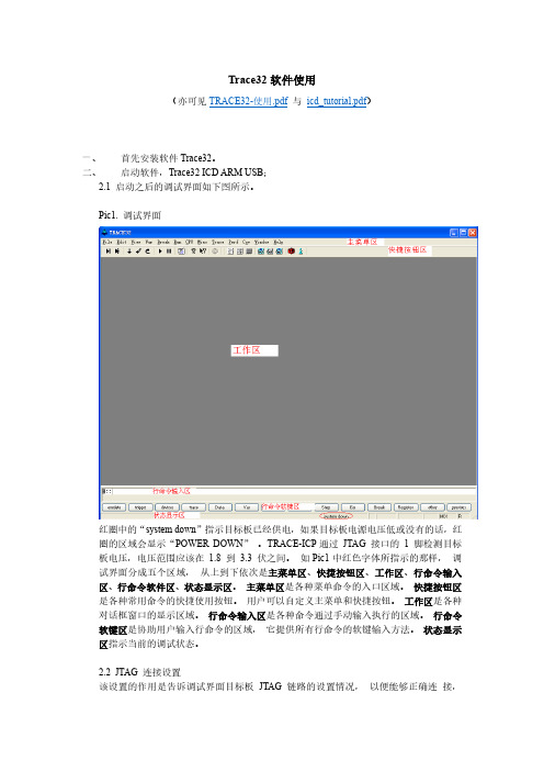
打开后的程序列表窗口可以有下面几种形式。 Pic24. 找不到源文件的程序列表窗口
对于上图所示的情形,需要用 Y.SPATH 命令指定源程序路径。如下图所示。 Pic25. 指定源程序路径(其一) Pic26. 带源程序的混合显示程序列表窗口(其二)
通过点击程序列表窗口上的“Mode”按钮可以切换混合和源码显示方式。 Pic27. 带源程序的源码程序列表窗口(其三)
这些设置主要包括: 1、 选择要调试的处理器型号。 2、 是否有多个器件串联在同一个 JTAG 链路里,连接顺序如何,每个器件的 JTAG IR
寄存器的宽度是多少。 (情况一) 3、 JTAG 时钟使用 TCK 还是 RTCK。TCK 由 TRACE-ICP 提供,一般情况下选用
10MHz。RTCK 是 TRACE-ICP 的 TCK 进入目标 JTAG 链路之后,从目标 JTAG 链路返回的时钟,它与目标处理器的时钟同步。一般情况下,具有睡眠模式的处理 器多选用 RTCK 作 JTAG 时钟, 如 ARM926EJ-S。 (情况二) 4、 通过 JTAG 与目标连接时,是否要先复位目标板。JTAG 口上的 SRST 信号产生复 位信号。 (情况三) 5、 通过 JTAG 与目标连接时,是否要停止目标处理器运行。 (情况四) 从主菜单“CPU”中选择“System Settings…” ,打开如下图所示对话框。从“CPU” 下拉菜单里选择要调试的处理器。 Pic2. System Settings 对话框
Pic29 中红框内的单选钮 IMASKASM 和 IMASKHLL 选择之后,单步时就会屏蔽中断。 用户也可以通过命令 sys.o imaskasm on 和 sys.o imaskhll on 来设置这两个选项。
十、 设置软件断点 设置软件断点可以在命令行输入命令 break.set <address> /soft 来实现,在命令中的 <address>代表程序地址,可以是程序中的函数名等符号。如下图所示。 Pic30. 用命令设置软件断点
- 1、下载文档前请自行甄别文档内容的完整性,平台不提供额外的编辑、内容补充、找答案等附加服务。
- 2、"仅部分预览"的文档,不可在线预览部分如存在完整性等问题,可反馈申请退款(可完整预览的文档不适用该条件!)。
- 3、如文档侵犯您的权益,请联系客服反馈,我们会尽快为您处理(人工客服工作时间:9:00-18:30)。
简介大家可能会对uTrace-ICD比较陌生,简单介绍一下,uTrace-ICD 是TRACE32-ICD的兼容机。
在这里我首先感谢国人的努力能让我用很少的RMB用上这么高端仿真器。
废话少说,下面我给大家介绍一下uTrace-ICD下具体实现Linux调试的具体过程。
大概介绍一下实现的具体原理,首先要有一块可用的目标板,我选用的是SMDK2410评估板。
编译环境是在虚拟VMware+RedHat9.0,调试环境是uTRACE。
在这里有个问题:就是在虚拟机下编译的arm linux内核如何传递给安装在Windows下的uTRACE。
我用的方法就是通过SMB服务器。
在Redhat9.0下配置SMB Server将arm linux的源码包通过网络共享的方式共享给Windows XP。
在XP下的Windows 资源管理器中将Redhat9.0共享的arm linux源码包影射为本地的一个虚拟盘比如是:Z盘。
这样uTRACE就可以象操作本地盘一样来读取Redhat9.0中的arm linux源码包以及编译生成的内核映像及内核的符号表。
对于uTRACE调试器来说,需要的东东就是包含调试信息的arm linux的内核映像vmlinux。
在这里要注意"包含调试信息",arm linux内核配置选项默认可能是不包含调试信息,如果将没有包含调试信息的vmlinux供uTRACE使用是实现不了内核源码级调试的。
所以我们在配置arm linux内核时一定要将包含内核调试信息的选项选上。
具在"kernel hacking"下。
其次uTRACE调试器需要的就是arm linux内核源码树。
调试器的工作原理就是通过给定的地址查找对应的符号表找到对应的符号,以及符号所在文件的路径信息,行信息等,近而找到源程序所对应的函数或变量。
简单介绍了uTRACE调试的基本原理,接下来,具体介绍一下arm linux内核,驱动,及应用层源码级调试的具体实现过程。
具体实现上一节简单介绍了uTrace-ICD调试的基本原理,下面将详细介绍调试的具体实现过程。
首先介绍一下我用的评估板SMDK2410的具体情况。
目标板是nor flash启动,大小为8M,SDRAM配置情况是32M,首地址是0x30000000。
软件配置情况:bootloader为ppcboot2.0,arm linux内核为2.4内核(实现过程对2.6内核也适用)。
第一步:配置虚拟机Redhat9.0编译环境。
安装交叉编译器arm-elf-gcc,解压arm linux源码包到“\SMDK2410\kernel”下,解压ppcboot到“\SMDK2410\ppcboot-2.0.0”下。
配置SMB Server将“\SMDK2410”目录网络共享出去。
在WindowsXP下同过网上邻居访问此目录并映像为本地磁盘“Z盘“,这样uTRACE 就可以像访问本地文档一样访问Linux下的文档了。
接下来编译ppcboot以及arm linux内核生成可执行映像,分别为ppcboot及vmlinux(注意在配置arm linux内核时将“Kernel Hacking”下“Include debugging Information in kernel binary”选项选上--生成调试信息)。
第二步:bootloader的调试。
以上开发环境都建立好,我们可以开始PPCBOOT的调试。
打开uTRACE-ICD调试软件,目标板上电。
在System Settings里选CPU 为S3C2410X,然后点UP使CPU进入调试状态。
打开反汇编窗口,命令为Data.list,可以查看当前PC处反汇编情况。
此时PC指向arm复位地址0x0即nor flash上内容的反汇编,此时我们也可以在flash上进行调试。
以下连结是反汇编图。
NOR Flash反汇编图此时查看的代码为Flash上固化的代码。
我们可以在Flash上进行单步调试,设置断点(注意在Flash上调试,只能设置Onchip断点,并且ARM9最多支持两个)。
如果要在Flash上实现源码级的调试,我们需要加载包含当前代码的带调试信息的目标文件。
对ppcboot来说,在ppcboot源代码目录下经交叉编译会生成ppcboot档,这个就是带调式信息的目标文件,本例就是要加载它,并且要注意,编译生成的目标文件与烧录到Flash上的代码是同一个版本,否则加载的调试信息将是错误的调试信息,代码对应上将会出错。
我们用命令行方式加载调试信息,命令如下:Data.LOAD.ElfZ:\ppcboot-2.0.0\ppcboot /gnu /nocode /strippart"/SMDK2410/" /path "Z:\"其中Data.LOAD.Elf指定是以ELF档格式加载Z:\ppcboot-2.0.0\ppcboot 指定文件的全路径/nocode 指定只加载调试信息,而不加载可执行代码,此时代码已经固化到Flash上,不需要再加载。
/strippart "/SMDK2410/"将调试信息中包含"/SMDK2410/"的部分去掉,因为可执行档是在linux环境中编译的,其中,编译出的调试信息中路径信息包含 "/SMDK2410/",由于Windows中无法以包含这个字符串的路径来搜索文件,所以要将其剥去。
/path "Z:\" 告诉uTRACE-ICD搜索路径在Z:\盘。
加载后,我们就可以以源码的方式来调试PPCBOOT了,如下:PPCboot源码调试图C与汇编混合模式:第三步:ARM Linux的调试。
首先将C:\T32\demo\arm\kernel\(uTrace安装目录)目录下的linux 整个目录拷贝到自己的工作目录,比如说E:\SMDK2410下。
Linux目录下是关于linux内核调试的一些配置文件。
打开E:\SMDK2410下linux 目录,新建一个目录取名为SMDK2410,将integrator目录下的内容完全拷贝到新建的目录中。
然后根据自己的目标板修改linux.cmm文件。
修改后载入uTrace调试运行。
linux.cmm脚本调试图单步调试运行linux.cmm脚本。
脚本会控制程序运行到linux内核入口start_kernel(具体实现是在start_kernel这个地址处设置Onchip端点)如下图所示:start_kernel处源码调试我们在这里可以单步跟踪内核启动流程,来学习内核的初始化过程并且可以通过符号表来定位程序或变量所在的文件,并且可以在程序或变量所在处设置断点(硬件断点或软件断点或WatchPoint断点)。
加载linux内核感应模块(即uTrace对arm linux的支持模块,因为uTrace可以支持多种操作系统调试比如Wince, Vxworks等基本上所有常用操作系统的调试,为了支持对应操作系统必须将对应操作系统的支持模块加载近来以支持该系统内核模块的调试),会在主菜单增加linux 主菜单,其下是关于linux内核的多种信息。
增加的linux菜单其中有Display Tasks,ps,Display Moduoles,Display File System等子菜单。
下面详细介绍其中每个菜单项的作用。
1.Display Tasks查看系统内核心中每个任务的详细状态。
Display Tasks菜单图双击任务前的magic可以查看每个任务的详细情况。
其中包含:relationship标志本进程父子进程关系。
Arguments标志本进程运行参数Environment标志本进程运行环境变量。
Open files 标志本进程打开的档Addresses 标志本进程代码地址,数据地址,堆栈地址及大小。
Code file 标志代码由哪些档组成,包括可执行文件,动态连接库,以及它们的起始地址。
Times 标志进程时间信息启动时间,休眠时间等。
TreeView任务图2.PS子菜单同linux控制台命令ps命令。
PS菜单命令图3.Display modules显示系统中加载的模块信息,包含模块名,模块的代码地址,数据地址,以及模块被使用情况。
Display modules菜单命令图4.Display File System查看系统中支持的文件系统的类型Display File System菜单命令图查看系统中加载的文件系统的类型Mounted file System菜单命令图查看/proc文件系统proc文件系统菜单命令图第四步:ARM Linux任务调试。
下面以调试简单的打印”Hello World”任务为调试对象,介绍任务级调试的实现方法。
可执行档为hello。
要调试hello可执行档,在linux.cmm档中执行do ../app_debug hello然后对app_debug.cmm做必要修改,主要是修改任务的调试信息。
Data.LOAD.Elf Z:\applications\hello\&process &spaceid:0 /gnu /nocode /noclear /strippart "/SMDK2410/" /path "Z:\"任务级源码调试图Display Tasks 可以看到在做好多了一个hello项。
Display Tasks命令图不单独发表文章了,就在这里接着写了!下面我在给大家介绍一下uTrace-ICD调试WinCE的具体实现方法。
我不是经常写文章,所以文章的组织能力比较差。
可能大家想知道的我没写出来或是写的不是很详细,我会慢慢完善,希望能给大家带来帮助。
以后我会陆续介绍uTrace-ICD调试VXwork,ucos,uclinux,ecos,nucleus,rtems,symbian等嵌入式操作系统的调试方法。
下面就具体介绍WinCE的具体调试方法。
WinCE调试的具体实现首先目标板还是选用SMDK2410评估板,上面有移植好的bootloader,如果没有移植好的,可以按上节所介绍的方法用uTrace来调试BootLoader。
软件环境的配置:安装WinCE开发编译环境Platform Builder。
利用Platform Builder 进行WinCE内核配置,裁减,编译生成Eboot.exe 及nk.exe目标文件供uTrace加载。
注意:编译时也要将生成调试信息的选项选上。
关于wince的调试的具体实现可参考uTRACE-ICD安装目录\T32\demo\arm\kernel\wince。