沧州天硕精密联轴器电子样本
7(下):金属弹性元件挠性联轴器
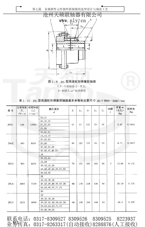
图 # $ !# 表 # $ !%
蛇形弹簧
蛇形弹簧主要尺寸 & ’’
联系电话:0317-8309527 8309526 8309525 8223937 — #"! — 业务传真:0317-8263317(自动接收)8288876(人工接收)
沧州天硕联轴器有限公司
!
第二章
蛇形弹簧联轴器
注: !" 若轴孔型式按 #$ % &’()* 与制造厂协商。 *" 质量是按无孔的计算近似值。
+" ,-,型蛇形弹簧联轴器 基本参数和主要尺寸见表 * / !*。 ,-.型带制动轮蛇形弹簧联轴器结构见图 * / 0,
图*/0
,-. 型带制动轮蛇形弹簧联轴器
图!"#
$%& 型高速蛇形弹簧联轴器
)—润滑孔; *—蛇形弹簧
’、 (—半联轴器; !—罩壳;
表 ! " ’’
( $+ , - ##./—!000) $%& 型高速蛇形弹簧联轴器基本参数和主要尺寸 , 11
联系电话:0317-8309527 8309526 8309525 8223937 — #"! — 业务传真:0317-8263317(自动接收)8288876(人工接收)
( $’ ( ) **+,—!---) $%& 型带制动轮蛇形弹簧联轴器基本参数和主要尺寸 ( ..
沧州天硕联轴器有限公司
联系电话:0317-8309527 8309526 8309525 8223937 — #"! — 业务传真:0317-8263317(自动接收)8288876(人工接收)
十字轴万向联轴器及其他类型万向联轴器(上)
沧州天硕联轴器有限公司
注: ! . 为在交变负荷下疲劳强度所允许的转矩。
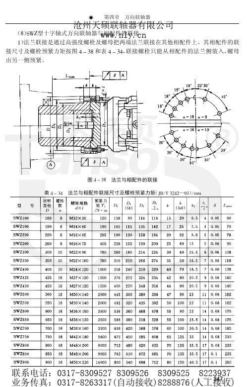
(##) /$0型十字轴式万向联轴器与相配件的联接 相配件的 /$0型万向联轴器通过高强度螺栓及螺母把母端的法兰联接在其他配件上, 联接尺寸及螺栓预紧力矩见图 ! " ## 和表 ! " #1。大规格 /$0型万向联轴器是通过端面齿、 高强度螺栓及螺母把两端的法兰联接在其他配件上, 相配件的端面齿尺寸及螺栓预紧力矩 见图 ! " #1 和表 ! " #+。
沧州天硕联轴器有限公司
注: +. ! / 为在交变负荷下按疲劳强所允许的转矩。 按需要确定。 0. " 为安装长度,
(#) $1型无伸缩短式万向联轴器 基本参数和主要尺寸见表 ! " +2。 $1型双联型式见图 ! " #,
图!"# 表 ! " +2
$1型无伸缩短式万向联轴器
( &’ ( ) **+,—#+) $1型无伸缩短式万向联轴器基本参数和主要尺寸 3--
图,-$
)*型标准伸缩法兰式万向联轴器
联系电话:0317-8309527 8309526 8309525 8223937 — #"! — 业务传真:0317-8263317(自动接收)8288876(人工接收)
表!"#
( &$ ’ ( ))*#—+*) $%型标准伸缩法兰式万向联轴器基本参数和主要尺寸 ’ ,,
表/0! #$%型十字轴式万向联轴器双联型式
联系电话:0317-8309527 8309526 8309525 8223937 —动接收)8288876(人工接收)
机械手-木琴演奏机械手的设计-说明书
机械手-木琴演奏机械手的设计-说明书摘要音乐机器人属于表演类特种机器人,其研究主要集中于国外,国内迄今未见有相关文献。
木琴演奏机械手是键盘型音乐机器人的一种,具有典型的运动机构、可选用可编程序控制器、PLC、微机等多种控制方式。
本文就木琴演奏机械手为研究对象,对于其机械部分和控制部分进行设计。
机械部分主要包括移槌装置、击槌装置和握槌机构。
其中移槌装置主要由直流伺服电动机、滚珠丝杠和滚动直线导轨副组成;击槌装置由步进电动机、减速器、机械手臂组成;握槌机构由夹具和护板组成。
控制部分由可编程控制器(PLC)控制直流伺服电动机和步进电动机来完成移槌定位和木槌击键动作。
关键词:木琴演奏机械手,移槌装置,击槌装置,可编程控制器(PLC)ABSTRACTMusic robots are special types of robots, their research focused on foreign and domestic so far there is no literature. Xylophone playing robots are one type of music keyboard robots, have typical of the sport organizations ,can use programmable logic controller, PLC, computer and other control methods In this paper, Xylophone playing robots to object of study, for the mechanical part and control part of the design. Mechanical parts mainly include the shifting hammer device, the hitting hammer device and the holding hammer device. The shifting hammer devicemainly consists of DC servo motor, Ball screw and rolling linear guides; the hitting hammer device consists of stepper motor, reducer, mechanical arm; the holding hammer device consists of clamp and retaining plateControl part by the programmable logic controller PLC control of DC servo motors and stepper motors to complete the shift position and mallet hammer keystroke action.Key words: Xylophone playing robots, shifting hammer device, hitting hammer device, programmable logic controller PLC 目录1 绪论1.1机器人的发展历史1.2音乐机器人的发展状况2 木琴演奏机械手的设计方案2.1机械部分和控制部分总体设计方案2.2拟采用的设计方案3 移槌装置的设计3.1滚珠丝杠的选型3.2移槌装置电机的确定3.3导轨的选型3.4联轴器的选用4 击槌装置的设计4.1一级减速齿轮的计算4.2轴的计算4.3轴的结构设计4.4估算击槌过程中机械手的运动范围及距离5 支架的设计5.1支架结构的设计5.2支架尺寸确定6 控制系统的设计6.1总体设计思路6.2系统中的检测元件6.3数字伺服系统的分类6.4可编程控制器PLC的选用6.5驱动器的选择6.6限位开关的选择6.7系统工作原理和I/O端口分配6.8软件设计7 结论参考文献致谢1绪论1.1机器人的发展历史机器人的历史并不算长,1959年美国英格伯格和德沃尔制造出世界上第一台工业机器人,机器人的历史才真正开始。
联轴器产品参数大全
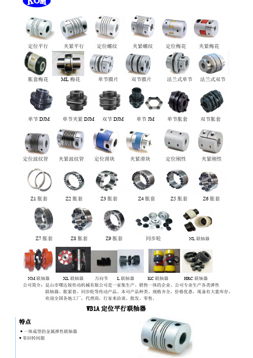
定位平行夹紧平行定位螺纹夹紧螺纹定位梅花夹紧梅花胀套梅花ML梅花单节膜片双节膜片法兰式单节法兰式双节单节DJM 单节夹紧DJM 双节DJM 单节JM 单节胀套双节胀套定位波纹管夹紧波纹管定位滑块夹紧滑块定位刚性夹紧刚性Z1胀套Z2胀套Z3胀套Z4胀套Z5胀套Z6胀套Z7胀套Z8胀套Z9胀套同步轮NL联轴器NM联轴器XL联轴器万向节L联轴器KC联轴器HRC联轴器公司简介:昆山市曙达锐传动机械有限公司是一家集生产、销售一体的企业。
公司专业生产各类弹性联轴器、胀紧套、同步轮等传动产品。
本司产品种类、规格齐全,价格优惠,现备有大量库存,欢迎全国各地工厂,代理商,行家来洽谈、批发、零售。
WB1A定位平行联轴器特点﹡一体成型的金属弹性联轴器﹡零回转间隙﹡弹性作用补偿径向、角向、轴向偏差﹡顺时针与逆时针回转特性完全相同﹡定位螺丝或加键槽固定﹡铝合金材质﹡适用于编码器、激光机选型举例例:WB1A-25-0810WB1A:定位平行型25:外径尺寸08:d1轴径尺寸10:d2轴径尺寸注:加键槽需另外注明型号Ød1 Ød2ØD L L1 M拧紧力矩轴径(N.m)WB1A-15□□□□ 3 4 5 6 6.35 8 15.5 23 3 M3 0.7 WB1A-17□□□□ 3 4 5 6 6.35 8 17.5 23 3 M3 0.7 WB1A-19□□□□ 3 4 5 6 6.35 8 19.1 19.1 2.55 M3 0.7 WB1A-25□□□□ 5 6 6.35 8 10 25.4 25.4 3.80 M4 1.7 WB1A-28□□□□ 6 6.35 8 10 12.7 28.6 28.6 4.00 M4 1.7 WB1A-38□□□□8 10 12 12.7 14 15 38.1 38.1 5.00 M5 3.8 WB1A-42□□□□10 12 14 15 16 18 20 42.0 50.0 7.80 M6 4.5 WB1A-50□□□□12 14 15 16 18 19 20 21 24 50.0 50.0 7.80 M6 7.0型号额定扭矩(N.m)最大扭矩(N.m)最高转速(rpm)径向偏差(m m)角向偏差(。
联轴器基本尺寸与参数

P G 型联轴器 L4
J3 X , 6 2 0 J / 70 - 9 B T 6 3 0 J3 义6 i0 0
m m
从动轴端: J 型轴孔, , A型键槽,, 0 轴孔长度 L =6 m d=3 m m, , 0 m的 P G 平行轴联轴器 L4
19 7
J / 70 一 9 s r 6 3 0
m m 表 1
1 7 7
, / 70 一 9 i T 6 3 s 0 续表 1
公称转矩
型号
T
N .m
nl l n
许用转速 C7 n
r mi / n
轴孔 直径
d d }
4 5 55 56 8 0
2 0 4 0 2 0 50
2 . 2 2 2 2 . 28 6
1.6 46 1 . 50 8
2 00 5 0
5 0 00 0
650 . 1
6 81 . 0 了 16 0 7 9 .3 6
1 . 59 9 1.3 67
1 . 7 45
8O 5 . 1 835 . 8
8 7 8 . 4 9 1 . 05 9 4 6 . 5
1 0 6 0
1 0 7 0
2 .2 20 2.8 29 2 . 39 2 2 . 4 8 5 2 . 57 5 2.4 66 2 . 75 2 2 . 83 9 2 . 92 5 3.0 0 1
液压机械 union 产品说明书

CHECK THE LABEL FOR PART NO. IDENTIFY THE SIZE AND TYPE FROM THIS TABLE. REFER TO PARTS LISTED UNDER NOMINAL SIZE.GROOVE indicates L.H. thread.PLAIN DIA indicates R.H. thread.Nominal Size ROTARY (R.E.B.) UNION ROTARY (C.B.N.) UNIONTYPE B.E.TYPE S.T.TYPE R.S.TYPE B.E.TYPE S.T.TYPE R.S.40 (1 ½")18104181051810618101181021810350 (2")17350172381735115471154721547365 (2 ½")18131181321813318240182411824280 (3") 17265172661726315477154781547990 (3 ½")174211742217423161711617216173100 (4")174241742517426161741617516176125 (5")176341763517636154861548715488150 (6")176371763817639167041670316702GROOVE indicates L.H. thread. PLAIN DIA indicates R.H. thread.Note! For the 125 (5") and 150 (6") there is a screwed Adjusting Ring at the flanged end of the body which is locked with a screw. This is similar to components 16 and 18 for the Rotary (C.B.N.) Unions and can be adjusted to give 6mm compression on the Bellow S/A if necessary.OVERHAUL OF ROTARY (R.E.B.) UNIONSa. Remove Nuts 13 and Washers which allows the removal of Adaptor 4.b. Remove Bellows Sub-Assembly and Gasket of Seal Kit 5.c. Remove Locking Screw 7 and unscrew Locking Ring 14 (RH Thread) and extract Spindle 15 complete with Ball Bearings etc.d. Remove Locking Screws from the Rubbing Ring of Seal Kit 5 and unscrew the Rubbing Ring (RH or LH thread) and remove Gasket.e. Thoroughly clean the Ball Bearing Kit 11 and check the condition of the bearings. (If there is any doubt replace the Bearing Kit pre-packing with an approved grease.) Re-grease the bearings if re-using.f. To replace Bearing Kit 11 remove Locking Screws 8, Bearing Locking Ring 9 (RH or LH Thread)and Nilos Ring 10 then press off Bearing Kit 11.g. If Adaptor 4 is type RS remove Locking Screw 3 unscrew Locking Ring 1, (RH Thread) and remove C.T. Bush 2.h. REPLACE :- Seal Ki t 5, Bearing Kit 11 and if type RS C.T. Bush 2.i. Thoroughly clean all parts before re-assembly, which is virtually the reverse of the above.j.Handle Seal Kit carefully to avoid damaging the lapped seal faces.k. After re-assembly run-in as indicated in the Installation Instructions and Test to ensure theseals are working correctly before refitting to the machine.OVERHAUL OF ROTARY (C.B.N.) UNIONSa.Remove Bolts and Washers 20, which allows the removal of Adaptor 4.b. Remove Bellows Sub-Assembly and Gasket of Seal Kit 5 and Spacer 6. (For the 125 (5") and 150 (6") Locking Screw 18 will need removing as Spacer 16 is screwed RH Thread and should be adjusted to give 6mm compression on the Bellows Sub-Assembly during refitting).c. Remove Locking Screws from the Rubbing Ring of Seal Kit 5, through the bleed port in Body S/A 19 and unscrew the Rubbing Ring (RH or LH Thread) and remove the Gasket and Thrust Pad 17.d. Remove Spindle 21 from Body S/A 19 and check the bore of the carbon bearing in Body S/A 19 for excessive wear and the bearing surface of Spindle 21 similarly.e. If the Adaptor 4 is the type RS remove Locking Screw 3, unscrew Locking Ring 1 and remove C.T. Bush 2f. REPLACE:- Seal Kit 5, Thrust Pad 17 as a minimum.REPLACE :- Body S/A 19 and Spindle 21 depending on condition. If a type RS replace C.T. Bush 2.g. Thoroughly clean all parts before re-assembly which is virtually the reverse of the above.h. Handle Seal Kit carefully to avoid damaging the lapped seal faces.i. After re-assembly run-in as indicated in the Installation Instructions and Test to ensure theseals are working correctly before refitting to the machine.NOMINAL SIZE 123456789101112131415RETAINER C/T BEARING SCREW ADAPTOR SEAL KIT BODY SCREW SCREW LOCKING RING NILOS RING BEARING KIT STUD NUT LOCKING RING SPINDLE R.S.S.T. B.E.R.E.B. C.B.N.40 (1 ½")18103/318103/2M5 x 0.818103/118102/118101/1S.1151/3S.1151/318104/8M6 x 1.0M5 x 0.818104/418104/5S.1235/017238/4M8 x 1.25 18104/218104/350 (2")15473/115473/3M5 x 0.815473/215472/115471/1S.1171/4S.1151/417238/11M6 x 1.0M4 x 0.717238/517238/12S.1235/117238/4M8 x 1.2517238/717238/865 (2 ½")15476/318133/2M6 x 1.018133/118132/118131/16S.1171/8S.1151/818131/15M6 x 1.0M5 x 0.818131/1018131/11S.1235/518131/6M10 x 1.518131/1318131/1480 (3")15479/315479/2M6 x 1.015479/115478/115477/1S.1171/5S.1151/517263/11M6 x 1.0M5 x 0.817263/517263/16S.1235/217423/1M12 x 1.7517263/717263/890 (3 ½")16173/316173/2M6 x 1.016173/116172/116171/1S.1151/6S.1151/617423/7M5 x 0.8M5 x 0.817423/217155/15S.1235/317423/1M12 x 1.7517423/817423/9100 (4")16176/316176/2M6 x 1.016176/116175/116174/1S.1151/6S.1151/617423/7M5 x 0.8M5 x 0.817423/217155/15S.1235/317423/1M12 x 1.7517423/817426/1125 (5")15488/315488/2M8 x 1.2515488/115487/115486/1S.1151/7S.1151/717635/3M12 x 1.75M12 x 1.7517635/517635/4S.1235/417635/7M16 x 217635/217635/1150 (6")16702/116702/3M8 x 1.2516702/216703/116704/1S.1151/7S.1151/717635/3M12 x 1.75M12 x 1.7517635/517635/4S.1235/417635/7M16 x217635/217637/1445RH LHREB CBNG AS K E T B E L L O W S S /A R U BB I N G RI N G GASKET15WE MANUFACTURE MANY SPECIALS. IF YOU HAVE ANY DOUBT CONTACT USGIVING THE PART No. AND SERIAL No. FROM THE IDENTIFICATION LABEL FITTED.WE MANUFACTURE MANY SPECIALS. IF YOU HAVE ANY DOUBT CONTACT US GIVING THE PART No. AND SERIAL No. FROM THE IDENTIFICATION LABEL FITTED.PLAIN DIA indicates R.H. thread.Note! For the 125 (5") and 150 (6") spacer 16 is screwed into Bearing S/A 19 and locked with screw 18. Compression on the Bellows S/A can be adjusted using these to obtain the correct compression of 6mm.161718192021NOMINAL SIZE SPACER THRUST PAD SCREW BEARING S/A BOLT SPINDLE 18101/1018101/5N/A 18101/12M8 x 1.2518101/840 (1 ½")15325/715325/11N/A 15325/15M8 x 1.2515472/350 (2")18240/618240/2N/A 18240/7M10 x 1.518240/565 (2 ½")15478/715478/10N/A 15478/14M12 x 1.7515478/1380 (3")16172/1216172/7N/A 16172/16M12 x 1.7516172/1090 (3 ½")16172/1216172/7N/A 16172/16M12 x 1.7516175/2100 (4")16702/1316702/9M12 x 1.7516702/16M16 x 2.015487/2125 (5")16702/1316702/9M12 x 1.7516702/16M16 x 2.016702/12150 (6")ROTARY (C.B.N.) UNIONSThe Filton Bellows Seal fitted to the Rotary (C.B.N.) Union is self-adjusting within its working life.The Rotary (C.B.N.) Union has dry carbon journal and thrust bearings operating on hardened surfaces. DO NOT GREASE. We advise periodic inspection for bearing wear.HEALTH & SAFETYThe Rotary Unions shown in this leaflet should not present any hazard when correctly fitted and used. To ensure satisfactory performance, every Rotary Union is run-in and leakage tested before despatch.De-pressurise and drain the system before removing Rotary Unions for repair.It is essential to use the correct hand of rotary connection thread to ensure the Rotary Union will not unscrew (see the Installation Instructions). If a shaft reverses rotation the connection thread should be locked or preferably a flanged connection should be use.At some time the seals in the Rotary Union will leak, so inspect daily. Also, ensure that leakages are not hazardous to personnel and that the Rotary Union is removed for repair immediately. If leakages are not attended to promptly, bearing seizure may occur causing flexible hose failure and massive leakage.Fit protective guards if leakages or the rotating spindle are likely to be hazardous to personnel.For hazardous application fit an excess torque detector to stop the machine before major damage occurs to flexible hoses causing massive leakage.With oil systems minor leakages occur due to the natural characteristics of oil preventing seal faces from contacting fully. Gaskets are now non-asbestos but existing units may have gaskets manufactured from compressed asbestos fibre fitted.These should be handled and disposed of according to the Asbestos Products (Safety) Regulations 1985.HAVE BEEN LEAKAGE TESTED – DISMANTLING INVALIDATES THE WARRANTY.INSTALLATIONRun in before fitting – rotate R.E.B. at 100 r.p.m. for 30 minutes for sizes 40 (1 ½") to 80 (3") and at 50 r.p.m. for 1 hour for other sizes and C.B.N. at half the speed for twice the time. Add system liquid if the seals squeak.(A TORQUE ARRESTOR SHOULD BE FITTED BUT THIS MUST NOT RESTRICT THE NATURAL MOVEMENT OF THE ROTARY UNION)MINIMUM LENGTHS FOR FLEXIBLE HOSENom size 20 ( ¾")25 (1")32/40 (1 ¼ "/1 ½ ")50/65 (2"/2 ½ ")80 (3")100/125/150 (4"/5"/6")Length mm 305380460610760915FILTON HOSE M240/4M240/5M240/ 6 & 7M240/ 8 & 9M240/10M240/ 11,12 & 13ALUMINIUM WASHER S593(PROVIDED WITH CLOCKWISE ROTATIONFITTED WITH A CURVE TO SUIT THE DIRECTION OF ROTATION AS SHOWN (Obtainable from Filton Limited)ELBOW S.1286 Filton Limited)GROOVE INDICATESL.H. THREAD ABUTMENT FACE MUST BE SQUARETYPE ST OR RSANTI CLOCKWISEROTATION DIAMETER INDICATES R.H. THREADCENTRE TUBE FOR TYPE STFIXED TO ROTARY UNIONFOR TYPE RS FIXED TO MACHINE (not supplied by Filton Limited unlessspecified)DO NOT:-1. FIX VALVES etc., directly onto the Rotary Union.2. Connect with Rigid Pipe.3. CLAMP THE ROTARY UNION.L.H.R.H.Caswell RoadSydenham Industrial EstateRoyal Leamington Spa Warwickshire United Kingdom CV31 1QF TEL: +44 1926 423191FAX: +44 1926 450610Email:******************.uk Web: ALL TYPES ARESUPPLIED WITH R.H. OR L.H. SPINDLE THREADS。
鼓形齿式联轴器选型手册(上)

联系电话:0317-8309527 8309526 8309525 8223937 — #"! — 业务传真:0317-8263317(自动接收)8288876(人工接收)
"
#
第五篇
无弹性元件挠性联轴器的选型设计与制造工艺
沧州天硕联轴器有限公司
— —中间轴长度, ! !— ""; — —外齿轴套轴孔长度, "— ""; — —中间套筒两端凸缘间距离, #— ""; — —#$%!型内齿套长度, $— ""; — —#$%"型内齿套长度, $& — ""。
图!"&
齿式联轴器 [!! ]
(# )* 型许用径向补偿量 !( ! +, - ./ &!01—02)
表!"!
3(4、 3(.、 3()及3(型许用径向补偿量 !( ! +, - ./ &!01—52)
注: 3(4 型的许用径向补偿量按 6 型给定。
见图 ! " :、 图 ! " ;, 并按下列 78 (# )*.、 3(9型鼓形齿式联轴器许用径向补偿量 !! , 三式计算。 (# )*.型: !! < " =$>! " < " =$>1?!@A < @8@’;’ " (##) 型: ( 3(9$ !! !@8@’;’ # B 18: $ ) ( # B 181 $1 ) 3(9#型: !! !@8@’;’ 式中 " 推荐用下列近似值: " < " A " 18: % (! " 5) (! " 1@) (! " 11)
十字轴万向联轴器及其他类型万向联轴器(下)
"
#
第五篇
无弹性元件挠性联轴器的选型设计与制造工艺
沧州天硕联轴器有限公司
注: !" !# 、 "! 、 # 的具体尺寸由设计者在表中规定的范围内确定。 当 !# !$%&’’ 时, 其轴孔键槽型式尺寸按 () %*+# 的规定, 轴孔长度 "! , 选短系 #" 轴孔 !# 若选扩用圆柱轴孔, 列; 当 !# , $%&’’ 时, 轴孔及键槽型尺寸由设计者自行规定。
万向联轴器
图 & ’ (! 表 & ’ (&
法兰与相配件的联接
法兰与相配件联接尺寸及螺栓预紧力矩 ( )* + , (-&-—.() + //
联系电话:0317-8309527 8309526 8309525 8223937 — #"! — 业务传真:0317-8263317(自动接收)8288876(人工接收)
式中
— —万向联轴器的寿命, #4— 7; — —理论转矩 (当 !+ #38, 轴承寿命 % < + #3337 时的理论计算 "— $ + /3339 : 5;,,
・ 值) , => 5; — —使用平均转矩, ・ " 平均 — => 5; — —材料系数, !5— ! 5 + #; — —转速系数, !, — ! , + /3*% : $ 3*##? ; — —平均转速, $— 9 : 5;,; — —折角系数, !!— !! + /*!? : $ 3*#!! ; — —平均合成轴成折角, (8) 。 !— 按式 (! " %3) 可绘制寿命计算图, 见图 ! " !%。 转速、 时间计算平均转矩及平均转速。 -* 按各阶段的使用转矩、 使用阶段 /、 …… & ; %、 #、 转矩 ( => ・ 5) "/ 、 "% 、 "# …… " @ ; 转速 ( 9 : 5;,) $/ 、 $% 、 $ # …… $ @ ; 时间比 (A) ’/ 、 ’% 、 ’ # …… ’ @ 。
- 1、下载文档前请自行甄别文档内容的完整性,平台不提供额外的编辑、内容补充、找答案等附加服务。
- 2、"仅部分预览"的文档,不可在线预览部分如存在完整性等问题,可反馈申请退款(可完整预览的文档不适用该条件!)。
- 3、如文档侵犯您的权益,请联系客服反馈,我们会尽快为您处理(人工客服工作时间:9:00-18:30)。
精密连轴器__联轴器偏差说明.选型.固定方式_14
精密连轴器_TS1定位螺丝固定波纹管联轴器_15
精密连轴器_TS1定位螺丝固定波纹管联轴器_16
精密连轴器_TS1L锁紧式波纹管联轴器_23 /index0.htm
精密连轴器_TS2定位螺丝固定型梅花联轴器_24 /index0.htm
精密连轴器_TS2定位螺丝固定型梅花联轴器_25 /index0.htm
精密连轴器_TS1C夹紧式波纹管联轴器_17
精密连轴器_TS1C夹紧式波纹管联轴器_18
精密连轴器_TS1Z波纹管胀套联轴器_19
TS3ZD胀套膜片联轴器
TS3ZF胀套法兰膜片联轴器
详细信息
TS3ZFD胀套法兰膜片联轴器
详细信息
详细信息
详细信息
详细信息
TS3K键槽法兰膜片联轴器 TS3KD键槽法兰膜片联轴器
TS4 平行线联轴器
TS4C夹紧平行线联轴器
详细信息
TS4K键槽平行线联轴器
详细信息
TS5 螺纹线联轴器
详细信息
TS5C夹紧螺纹线联轴器
精密连轴器_TS7Z刚性联轴器69
精密连轴器_TS9编码器联轴器_70
精密连轴器_TS10钢制弹簧联轴器_71 /lianzhouqi.html
精密连轴器_封面_01 /index0.htm
精密连轴器_天硕联轴器公司简介_02 /index0.htm
伺服电机、编码器、微型联轴器
TS1 波纹管联轴器
TS1C夹紧波纹管联轴器
TS1Z胀套波纹管联轴器
TS1BC大扭矩波纹管联轴器
精密连轴器_TS7C夹紧螺丝固定微型刚性联轴器_65 /com2685.html
精密连轴器_TS7C夹紧螺丝固定微型刚性联轴器_66
精密连轴器_TS7Z刚性联轴器_67
精密连轴器_TS3KD多节键槽联接膜片联轴器_47
精密连轴器__TS3KD多节键槽联接膜片联轴器48
精密连轴器_TS4平行线联轴器(定丝固定)_49
详细信息
TS6 十字滑块联轴器
详细信息
TS6C夹紧十字滑块联轴器
详细信息
TS7 刚性联轴器
详细信息
TS7C夹紧刚性联轴器
TS7Z刚性联轴器
详细信息
详细信息
TS8 编码器联轴器
详细信息
详细信息
TS9 编码器联轴器
TS10 弹簧螺旋钢联轴器
详细信息
TS11C夹紧式万向节
详细信息
详细信息
详细信息
详细信息
精密连轴器_天硕联轴器部分设备图片_03
精密连轴器_TS2C夹紧螺丝固定型梅花联轴器_26
精密连轴器_TS2C夹紧螺丝固定型梅花联轴器_27
精密连轴器_TS2Z梅花弹性体胀套联轴器_28
精密连轴器_天硕联轴器部分产品图片_04
精密连轴器_天硕联轴器部分产品图片_05
精密连轴器_天硕联轴器部分产品图片_06
精密连轴器_TS6C夹紧式十字滑块联轴器_62 /com2685.html
精密连轴器_TS7定位螺丝固定微型刚性联轴器_63
精密连轴器_TS7定位螺丝固定微型刚性联轴器_64
精密连轴器_TS4平行线联轴器(定丝固定)_50
精密连轴器_TS4C夹紧式平行线联轴器_51
精密连轴器_TS4C夹紧式平行线联轴器_52
精密连轴器_天硕联轴器部分产品图片_10
精密连轴器_目录_11
精密连轴器_目录_12
精密连轴器_联轴器偏差说明.选型.固定方式_13
精密连轴器_TS3D多节夹紧定式膜片联轴器_32
精密连轴器_TS3D多节夹紧定式膜片联轴器_33 /qy-10025611.html
精密连轴器_TS3F法兰膜片联轴器_34 /qy-10025611.html
精密连轴器_TSC11夹紧式万向节_72 /lianzhouqi.html
精密连轴器_TSL铁材质联轴器_73
精密连轴器_封面_74
精密连轴器_联轴器样本图片_75 /showroom/lianzhouqi
精密连轴器_TS3ZF胀套法兰膜片联轴器_41
精密连轴器_TS3ZF胀套法兰膜片联轴器_42
精密连轴器_TS3ZFD多节胀套法兰膜片联轴器_43
精密连轴器_TS2Z梅花弹性体胀套联轴器_29
精密连轴器_TS3单节夹紧式膜片联轴器_30 /
精密连轴器_TS3单节夹紧式膜片联轴器_31
精密连轴器_TS3ZFD多节胀套法兰膜片联轴器_44
精密连轴器_TS3K单节键槽联接膜片联轴器_45
精密连轴器_TS3K单节键槽联接膜片联轴器_46
精密连轴器_TS6顶丝固定式十字滑块联轴器_59 /zhidongqi
精密连轴器_TS6顶丝固定式十字滑块联轴器_60 /com2685.html
精密连轴器_TS6C夹紧式十字滑块联轴器_61 /com2685.html
精密连轴器_TS3FD多节法兰膜片联轴器_35 /qy-341449.html
精密连轴器_TS3FD多节法兰膜片联轴器_36 /qy-341449.html
精密连轴器_TS3Z单节胀套膜片联轴器_37
详细信息
TS1L锁紧式波纹管联轴器
详细信息
TS2 梅花联轴器
详细信息
TS2C夹紧梅花联轴器
详细信息
TS2Z胀套梅花联轴器
详细信息
详细信息
详细信息
TS3 单节夹紧膜片联轴器 TS3D多节夹紧膜片联轴器
TS3F夹紧法兰膜片联轴器
详细信息
TS3FD多节法兰膜片联轴器
详细信息
TS3Z胀套膜片联轴器
详细信息
详细信息
精密连轴器_TS4K键槽平行线联轴器_53
精密连轴器_TS4K键槽平行线联轴器_54
精密连轴器_TS5螺旋线联轴器(顶丝固定)_55
精密连轴器_天硕联轴器部分产品图片_07
精密连轴器_天硕联轴器部分产品图片_08
精密连轴器_天硕联轴器部分产品图片_09
精密连轴器_TS1Z波纹管胀套联轴器_20
精密连轴器_TS1BC夹紧固定大扭矩波纹管联轴器_21
精密连轴器_TS1BC夹紧固定大扭矩波纹管联轴器_22
精密连轴器_TS5螺旋线联轴器(顶丝固定)_56
精密连轴器_TS5C螺旋线联轴器(夹紧式)_57 /lianzhouqi
精密连轴器_TS5C螺旋线联轴器(夹紧式)_58 /lianzhouqi
精密连轴器_TS3Z单节胀套膜片联轴器_38
精密连轴器_TS3ZD多节胀套膜片联轴器_39
精密连轴器_TS3ZD多节胀套膜片联轴器_40