2018年规模以上电子信息制造业增加值同比增长13.1%
TCCAS 017-2021 水泥水化热测定方法(等温传导量热法)

。 6 7 + , - . / ! ( " R ) *
3.1 -.(0>1(? 犻狊狅狋犺犲狉犿犪犾犺犲犪狋犮狅狀犱狌犮狋犻狅狀犮犪犾狅狉犻犿犲狋犲狉
6 ?LMN
6.1 1(?
、 、 、 , 1 。 3 =>6xVM} >W >e7 OU-2L \*: GI =>6 g
20μW, x 5¡¢£¤:;OU£k4^>`1q"
x^dp¥¦5¡¢£¤:;OUq
10μW, 20μW。 ±0.2 ℃, "
=>6^>`15q§"
4
犜/犆犆犃犛017—2021
o p 犃
(425)
-.(0>1(?qr^_+,
犃.1 st
( ) 。 RJK%.ÿLM>NO=>6 z6{|=>6 PQ?@01
犃.2 ^_HI
, x">e7üý^PþtuG:;OUný^W^b3 8 ( > ` 1 ÿ x ! " # $ î i ,
。 A.1 8¿=%&>'^]>` 1 í 9 ( > ` 1 G > e 7 s P ) v ^ x & * « " #
9.2 fghi
: ; Õ Y 8 ( y 5 Ö × Ø > Ù Ú ,| N 5.00g±0.01g { | : O " : ; O U Å y ,Û 2.00g±
0.01g 60s±5s , , , -{ ÜÒ(½¼¾Ë̽ ½8(y5ÝÞ{|ßàágâ㣠½4vü
2801.5挥发性有机物排放标准第5部分_表面涂装行业

Word 格式ICS 87.010G50 DB37 山东省地方标准DB 37/ 2801.5 —2018挥发性有机物排放标准第 5 部分:表面涂装行业Emission standard of volatile organic compounds Part 5: Surface coating industry2018 - 04 - 23 发布2018 - 10 - 23 实施山东省环境保护厅发布山东省质量技术监督局发布DB37/ 2801 《挥发性有机物排放标准》已经或计划发布以下部分:——第1部分:汽车制造业;——第2部分:铝型材工业;——第3部分:家具制造业;——第4部分:印刷业;——第5部分:表面涂装行业;——第6部分:有机化工行业;——第7部分:其他行业。
本部分为DB37/ 2801 的第5部分。
本部分按照GB/T 1.1 —2009给出的规则起草。
本部分由山东省环境保护厅提出。
本部分由山东省环保标准化技术委员会归口。
本部分起草单位:山东省环境规划研究院、山东省环境监测中心站。
主要起草人:史会剑、王宝琳、谷树茂、李恒庆、袁琦、王志峰、苏志慧。
引言山东省表面涂装企业或生产设施排放水污染物、大气污染物、恶臭污染物、环境噪声适用相应的国家和地方标准,产生固体废物的鉴别、处理和处置适用相应的国家固体废物污染控制标准。
挥发性有机物排放标准 第 5 部分:表面涂装行业1 范围本标准规定了山东省表面涂装企业或生产设施涂装工序的挥发性有机物排放限值和监测要求, 以及 标准的实施与监督等有关要求。
本标准适用于现有的表面涂装企业或生产设施涂装工序挥发性有机物排放管理, 以及新、 改、扩建 项目的环境影响评价、 环境保护设施设计、 竣工环境保护验收、 排污许可及其投产后的挥发性有机物排 放管理。
汽车制造业、铝型材工业和家具制造业分别执行DB37/ 2801《挥发性有机物排放标准》的第 1部分:汽车制造业、第 2部分:铝型材工业和第 3部分:家具制造业,不适用本标准。
QMZ-J54.006-2018_注塑件及装配通用技术条件(含AM1)
注塑件及装配通用技术条件(发布日期:2018-5-22)1 范围本标准规定了注塑件的分类、技术要求、检验方法、检验规则及标志、包装、运输、贮存。
本标准适用于空调器用注塑件(及组件)。
注:在没有特别说明的情况下本标准适用于制冷事业本部所有注塑件(不包括喷涂塑料件),如果出口产品或某产品对注塑件有特殊要求时(如色差、光洁度、外观),应在相关的技术文件中提出。
2 规范性引用文件下列文件中的条款通过本标准的引用而成为本标准的条款。
凡是注日期的引用文件,其随后所有的修改单(不包括勘误的内容)或修订版均不适用于本标准,然而,鼓励根据本标准达成协议的各方研究是否可使用这些文件的最新版本。
凡是不注日期的引用文件,其最新版本适用于本标准下列术语和定义适用于本标准 GB/T 191 包装储用图示标志GB/T12672 丙烯腈-丁二烯-苯乙烯(ABS)树脂 GB/T 4857.5 包装 运输包装件 跌落试验方法 QMZ-J84.014 跌落试验评价方法QMZ-J80.001 空调器用零部件阻燃性试验导 QMZ-J80.002 塑料和泡沫材料的可燃性试验 QMZ-J11.010 产品中限制使用有害物质的技术标准 QMZ-J40.002 电批、力矩扳手使用规程 QMZ-J10.006 质量特性重要度分级QMZ-J11.012 产品中限制使用有害物质的测试方法GB/T 2828.1 计数抽样检验程序 第1部分:按接收质量限(AQL)检索的逐批检验抽样计划 3 产品分类 3.1 透明注塑件 3.2 非透明注塑件按非透明注塑件对空调器外观的影响程度,可分为Ⅰ、Ⅱ、Ⅲ三类。
a) Ⅰ类:指外观质量要求高的重要零部件。
如:座吊机室内机面板正面、出风框等,分体挂壁式室内机面板、面框正面、出风框(导风条、导风板),一面出风面板、格栅、导风板等。
★★ 机密 ★★保密期限5年b)Ⅱ类:指外观质量要求高的次要零部件。
如:分体挂壁式室内机底盘、面框两側面等。
《盾构法隧道同步注浆材料应用技术规程》T

d o i :10.3963/j .i s s n .1674-6066.2022.06.030‘盾构法隧道同步注浆材料应用技术规程“T /C E C S 563 2018标准解读韩 旭1,庞奇林2,朱先发1,张 伟1,宋普涛3,王 晶3(1.南通城市轨道交通有限公司,南通226000;2.中铁十二局集团第四工程有限公司,西安710024;3.中国建筑科学研究院有限公司,北京100013)摘 要: ‘盾构法隧道同步注浆材料应用技术规程“T /C E C S563 2018,为国内首部针对盾构同步注浆材料配制㊁生产㊁施工及检验编制的标准㊂为确保标准的贯彻和推广,对标准编制背景㊂主要技术内容进行详细解读,并提出标准贯彻落实过程中需要注意的问题㊂关键词: 编制背景; 主要内容; 技术要点; 经济与社会效益I n t e r p r e t a t i o no f t h e S t a n d a r dT /C E C S 563 2018‘A p p l i c a t i o nT e c h n i c a l S p e c i f i c a t i o no f S y n c h r o n o u sG r o u t i n g Ma t e r i a l f o r S h i e l dT u n n e l “HA N X u 1,P A N GQ i -l i n 2,Z HUX i a n -f a 1,Z HA N G W e i 1,S O N GP u -t a o 3,WA N GJ i n g3(1.N a n t o n g U r b a nR a i lT r a n s i tC o m p a n y ,N a n t o n g 226000,C h i n a ;2.C h i n aR a i l w a y 12t hB u r e a uG r o u p N o .4E n g i n e e r i n g C o ,L t d ,X i a n710024,C h i n a ;3.C h i n aA c a d e m y o fB u i l d i n g R e s e a r c h ,B e i j i n g 100013,C h i n a )A b s t r a c t : T /C E C S563 2018i s t h e f i r s t n a t i o n a l s t a n d a r d f o r p r e p a r a t i o n ,p r o d u c t i o n ,c o n s t r u c t i o na n d i n s p e c t i o n o f s y n c h r o n o u s g r o u t i n g m a t e r i a l f o r s h i e l d t u n n e l .I no r d e r t o e n s u r e t h e i m p l e m e n t a t i o na n d p r o m o t i o no f t h e s t a n d -a r d ,t h eb a c k g r o u n da n dm a i n t e c h n i c a l c o n t e n t o f t h e s t a n d a r da r e i n t e r p r e t e d i nd e t a i l ,a n d t h e p r o b l e m s t h a t n e e d t o b e p a i da t t e n t i o n t o i n t h e f u t u r e i m p l e m e n t a t i o no f t h e s t a n d a r da r e p u t f o r w a r d .K e y wo r d s : c o m p i l a t i o nb a c k g r o u n d ; m a i n c o n t e n t s ; t e c h n i c a l p o i n t s ; e c o n o m i c a n d s o c i a l b e n e f i t s 收稿日期:2022-08-05.作者简介:韩 旭(1978-),硕士,高级工程师.E -m a i l :1371898105@q q.c o m 当前国内盾构隧道同步注浆材料种类繁多㊁材料的性能差异较大,不同注浆材料适用的水文地质环境不同[1-10]㊂由于尚无成熟的标准㊁规范对盾构法隧道用注浆材料的选择㊁性能指标及应用等提出规定,设计文件中鲜有关于盾构法隧道同步注浆材料选择及关键性能控制指标的相关要求,施工过程中注浆材料及原材料的选用㊁注浆配合比设计㊁注浆材料生产施工环节等均由施工现场技术人员自行控制㊂由于人为认知水平的差异,往往存在因注浆材料的选择及应用不当导致注浆施工效果差㊁注浆后地表沉降严重㊁渗漏等各类问题,严重影响了盾构施工的质量与工程的安全性㊂由此可见,制定一本针对地铁盾构隧道用水泥基注浆材料的产品标准是必须且必要的,这将有利于对地铁盾构隧道用注浆原材料的质量控制,规范水泥基注浆材料的生产和检验,做到地铁盾构隧道用水泥基注浆材料安全适用㊁经济合理㊁质量可靠㊁技术先进,实现地铁盾构隧道用水泥基注浆材料在地铁盾构隧道建设中得到科学㊁合理㊁有效地利用㊂根据中国工程建设标准化协会‘关于印发<2015年工程建设协会标准制订㊁修订计划>的通知“(建标协字[2015]099号)的要求,批准中国建筑科学研究院与南京易发新材料科技有限公司会同南通城市轨道交通有限公司等有关单位共同编制C E C S 标准‘盾构法隧道同步注浆材料应用技术规程“(以下简称‘规程“)㊂规程于2018年12月18日公告发布,自2019年5月1日起实施㊂1 主要内容与技术要点标准共分7章和3个附录,主要技术内容包括:总则㊁术语和符号㊁基本规定㊁原材料㊁注浆材料配合比及711建材世界 2022年 第43卷 第6期性能㊁同步注浆施工㊁质量检验与验收㊂1.1盾构工程同步注浆材料及其原材料性能要求的提出通过国内典型盾构工程同步注浆用原材料调研㊁总结以及充分的试验验证,在广泛征求意见的基础上汇总㊁归纳㊁探讨㊁分析㊁总结,对盾构工程同步注浆材料及其原材料种类及性能作出要求㊂调研发现,现场盾构工程同步注浆材料用水泥以P O42.5等级水泥为主;砂以河砂为主,规格为中砂;掺合料以Ⅱ级粉煤灰为主,也有矿粉㊁石灰石粉等掺合料;消石灰多为钙质,且C a O+M g O含量大于85%;膨润土多为钠基㊂经充分调研:目前盾构工程施工注浆所用的同步注浆材料主要分为水泥基㊁消石灰基两大类㊂水泥基盾构工程同步注浆材料主要测试浆液密度㊁泌水率㊁稠度及其经时损失㊁流动度及其经时损失㊁凝结时间㊁抗压强度㊁水陆强度比和结石率指标㊂标准启动会过程中编制组内部一致讨论通过,增加水泥基盾构工程同步注浆材料的分层度指标用于进一步表征其匀质性,增加水陆强度比指标用以表征其抗水分散性能㊂按照目前常用水泥基同步注浆材料的配合比参数的验证试验结果表明,水泥基盾构工程同步注浆材料浆液湿表观密度均不小于1800k g/m3,泌水率均不大于5%,稠度为10~14c m范围内,浆体的结石率不小于95%,1d强度不小于0.2M P a㊁7d强度不小于1.5M P a㊁28d强度不小于2.5M P a㊂消石灰基盾构工程同步注浆材料主要测试浆液密度㊁泌水率㊁稠度㊁抗压强度㊁结石率等性能指标㊂标准启动会过程中编制组内部一致讨论通过,增加消石灰基盾构工程同步注浆材料的分层度指标用于进一步表征其匀质性,尝试增加p H指标用以表征其抗水分散性能㊂系统的调研结果表明,消石灰基盾构同步注浆材料浆液湿表观密度均不小于1800k g/m3,泌水率几乎均不大于5%,结石率均不小于95%,稠度在8~14c m范围内,凝结时间范围相对较大,且波动无明显规律相对离散㊂由p H值试验结果可知,利用p H 值结果评价消石灰基盾构同步注浆材料的试验方法仍不够成熟㊂此次标准制定过程中,试验方法和盾构同步注浆原材料及相应的配合比均参数的确定,主要参考的是目前实际盾构工程常用的原材料和配合比参数㊂为了避免试验结果受试验条件和人为主观因素的影响,主编单位按照开题的任务分工,分别安排不同的编制组成员单位进行验证试验㊂但由于部分性能指标及试验方法是新提出的,其科学性和可操作性仍需要验证㊂相对成熟的性能指标及试验方法,考虑水泥基同步注浆材料与石灰基同步注浆材料的强度较低,凝结时间可控,水陆强度比等部分性能试验方法相对科学㊁可行㊂因此,标准规定的盾构注浆材料的性能指标主要应以实际验证性试验结果为依据㊂而对于评价水下不分散性能的p H值指标及试验方法,以及消石灰基的注浆材料的凝结时间指标及试验方法,考虑其试验结果离散性大㊁试验方法可操作性较差,潜在的人为试验误差相对较大,故标准暂未规定相应的性能指标参数要求及对应的试验方法㊂经充分验证,并经广泛征求意见以及审查会专家讨论一致通过后形成的同步注浆材料性能指标如表1所示㊂水泥基单液同步注浆浆液硬化后的性能应符合表2的规定㊂表1同步注浆浆液的性能要求项目技术要求水泥基单液消石灰基单液稠度/mm100~13090~130稠度经时损失/(mm㊃h-1)ɤ10ɤ10流动度/mmȡ160-流动度经时损失/(mm㊃h-1)ɤ20-泌水率/%ɤ3.5-分层度/mmɤ6凝结时间/h10~24-表2水泥基单液同步注浆浆液硬化后的性能要求项目抗压强度/M P a3d28d水陆强度比/%28d结石率/%技术要求ȡ0.5ȡ2.5ȡ65ȡ95.0同时,规定消石灰基单液同步注浆材料24h抗剪屈服强度不应小于1200P a㊂水泥-水玻璃双液同步注浆材料的浆液配合比和浆液性能应满足施工和设计要求,并应通过试验确定㊂8111.2盾构工程注浆材料推荐配合比关键参数与配合比设计方法的提出在充分调研的基础上汇总㊁归纳㊁分析㊁总结,提出了初步的盾构工程注浆材料推荐配合比关键参数与配合比设计方法㊂通过广泛内部征求意见,反复讨论研究,形成盾构工程注浆材料推荐配合比关键参数与配合比设计方法㊂在征求意见稿阶段,根据试验结果,确定较为典型的现场盾构注浆材料施工配合比参数如下:水泥基盾构注浆材料现场施工配合比控制范围为:水胶比0.45~0.79,胶砂比0.45~0.75,水泥占胶凝材料质量分数0.17~0.26,膨润土占胶凝材料质量分数0.14~0.18,设计湿表观密度1817~1908k g/m3㊂石灰基盾构注浆材料现场施工配合比控制范围为:水胶比0.58~0.7,胶砂比0.36~0.69,消石灰占胶凝材料质量分数0.17~0.19,膨润土占胶凝材料质量分数0.09~0.14,设计湿表观密度1830~1910k g/m3㊂在全国范围内征求意见过程中,相关专家提出:在采用一定增稠剂㊁絮凝剂等外加剂手段或其他膨润土替代材料时,可降低膨润土掺量㊂膨润土掺量占胶凝材料用量低至5%时,同步注浆材料浆液施工性能依旧满足要求,经核验后,将注浆材料膨润土掺量推荐控制值降低为5%㊂征求意见过程中,参考相关专家提出的意见,水泥或消石灰用量宜只规定掺量下限,两者掺量下限可达15%,且不宜规定上限㊂水泥或消石灰掺量超过征求意见稿中暂定推荐指标上限范围时,盾构注浆材料浆液施工性能依旧满足要求,且施工后注浆效果良好㊂经核实后将注浆材料水泥及消石灰推荐掺量均调整为不小于15%㊂标准审查过程中与会专家一致认为,消石灰基盾构注浆材料水胶比控制上限控制指标偏低,已有很多消石灰基盾构注浆材料水胶比达0.8的盾构施工案例,且盾构注浆效果良好,建议将消石灰基盾构注浆材料水胶比上限控制为0.8㊂同时部分专家提出,部分消石灰基注浆材料中胶砂比可低至0.3,也有部分消石灰基注浆材料未采用砂,其胶砂比可达1/1,且这两种情况下注浆效果均达到了预期的要求㊂由于现在关于消石灰基盾构注浆材料的填充㊁固结机理的研究尚不明确,为避免标准对先进产品应用的限制,鼓励先进,经审查会讨论后一致同意,将胶砂比推荐参数调整为不小于0.3㊂综上,盾构注浆材料配合比推荐参数如表3及表4所示㊂表3水泥基同步注浆材料配合比推荐参数水胶比胶砂比膨润土掺量/%水泥掺量/%0.45~0.80ȡ0.45~20ȡ15注:配合比中胶结材料包括水泥㊁膨润土和粉煤灰等矿物掺合料,掺量均为该材料占胶结材料总量的质量百分比;外加剂掺量根据注浆浆液性能要求试验确定;有其他材料可替代膨润土时,通过试验确定㊂表4消石灰基同步注浆材料配合比推荐参数水胶比胶砂比膨润土掺量/%消石灰掺量/%0.55~0.80ȡ0.35~15ȡ15注:配合比中胶结材料包括消石灰㊁膨润土和粉煤灰等矿物掺合料,掺量均为该材料占胶结材料总量的质量百分比;有其他材料可替代膨润土时,通过试验确定㊂1.3盾构工程同步注浆材料及其原材料性能试验方法的提出盾构工程同步注浆材料用原材料均有相应的国家标准或行业标准,故同步注浆材料用原材料试验方法均参照相关国家或行业标准进行㊂盾构工程同步注浆材料的性能试验主要参照国内现行混凝土㊁砂浆㊁灌浆料㊁水泥土等试验方法进行,并通过验证性试验对试验方法的可行性及推荐性能指标的合理性进行分析㊂对有争议的试验方法,通过广泛的征求意见㊁集思广益并结合验证试验,分析提出合理试验方法㊂对于可行性差的用于标准盾构工程同步注浆材料抗水分散性能的p H试验方法以及用于测试消石灰基同步注浆材料的凝结时间的试验方法㊂由于暂无更合理的试验手段,此次标准编制中暂没有纳入㊂标准审查会期间,各与会专家对盾构工程同步注浆材料及其原材料性能试验规定的试验方法表示肯定,并指出会后需仔细核对试验方法中出现的公式的单位和量纲,以确保单位使用的合理㊁准确㊁统一性㊂1.4盾构工程同步注浆材料生产、施工及验收在广泛调研的基础上,参照国家标准‘盾构法隧道施工与验收规范“G B50446[11]等国内相关标准,并结911合盾构工程同步注浆材料的性能特点及不同施工环境特点,以保证盾构工程同步注浆质量为目的,对盾构工程同步注浆材料生产㊁施工及验收提出要求,并在广泛征求意见的基础上,归纳㊁总结㊁分析,对盾构工程同步注浆材料生产㊁施工及验收作出合理的规定㊂审查会期间,部分专家对注浆施工一般规定㊁同步注浆材料检验批次㊁注浆施工注意事项及验收中个别条文提出意见,并为标准进一步修改完善提供建议㊂2标准实施后的经济效益和社会效益‘规程“是我国盾构工程同步注浆材料方面的第一本重要的技术性标准,适用于我国盾构工程同步注浆材料的制备㊁生产㊁施工㊁设计与质量控制㊂‘规程“发布实施后,仍将为我国的地铁隧道等盾构工程注浆材料及其施工后质量的控制与提升提供技术支撑,避免盾构工程同步注浆材料参差不齐㊁盾构工程同步注浆施工质量无章可依的局面,进一步提升盾构工程质量,减少因盾构同步注浆材料及应用不合理产生的实际注浆量高㊁注浆施工难度大㊁注浆施工进度慢等直接及间接经济损失,具有良好的经济效益㊂‘规程“发布实施后,可规范㊁提升盾构注浆工程质量,避免因注浆材料使用不当导致的注浆填充密实性差㊁注浆效果差等问题,避免由此引发的渗漏㊁沉降等工程质量问题以及可能引起的安全事故等社会问题,其社会效益显著㊂3尚存在主要问题与后续工作1)消石灰基盾构工程同步注浆材料的抗水分散性能㊁凝结时间性能暂无科学㊁可操作性的试验方法,在标准发布实施后,需进一步深入研究,尽快确定性能指标要求及对应的试验方法㊂2)由于现阶段存在研究成果相对较少㊁注浆材料成本较高㊁工程现场实际使用较少等情况,该标准中未包含针对滨海环境㊁盐渍土等具有侵蚀性介质环境的,具有抗腐蚀性能要求的同步注浆材料的有关性能要求和规定㊂但随着我国各地地铁工程的加速推进,盾构注浆材料的防腐蚀指标也是不得不考虑的指标,而且随着注浆材料及施工技术的进步㊁新材料与新工艺的发展,在后续的标准修订中,会结合工程实际情况纳入经济性良好㊁施工性能良好的耐腐蚀型盾构工程同步注浆材料产品㊂3)继续开展消石灰基盾构工程同步注浆材料注浆效果的调研工作㊂消石灰基盾构工程同步注浆材料具有强度低㊁强度增长缓慢的特点,在江浙等地区应用广泛㊂调研发现当前该种浆料盾构注浆施工效果较好,但部分学者对该种浆料的填充㊁支撑机理仍有一定的质疑㊂前期调研过程中有关专家指出,该种浆料早期对盾构空隙的填充与支撑作用主要由浆料中的砂粒之间的嵌锁作用来完成,对于相应的试验方法能否科学反映这种嵌锁作用,仍存疑问㊂因此,关于消石灰基盾构工程同步注浆材料早期对盾构空隙的填充与支撑机理,后续的研究工作仍有待加强㊂参考文献[1]黄大维,罗仲睿,罗文俊,等.盾构隧道施工同步注浆材料流动性测试方法及影响因素分析[J].中国铁道科学,2022,43(3):94-102.[2]王爱华.地铁盾构高性能同步注浆材料的应用研究[J].现代交通技术,2021,18(5):78-82,87.[3]万泽恩,李树忱,赵一民,等.富水地层盾构隧道同步注浆惰性充填材料配比与试验研究[J].土木工程学报,2021,54(7):123-132.[4]朱先发,宋普涛,杜峰,等.富水砂层高性能盾构同步注浆材料的配制及现场注浆性能研究[J].新型建筑材料,2021,48(3):98-101.[5]宋维龙.碱激发工业废渣基盾构隧道壁后注浆浆液特性与扩散机理研究[D].南京:东南大学,2021.[6]王晶,宋普涛,唐晶晶,等.水泥基盾构同步注浆材料的性能研究[J].新型建筑材料,2018,45(10):22-25.[7]宋普涛,王晶,周永祥,等.耐水抗渗型高性能盾构同步注浆材料性能研究[J].硅酸盐通报,2017,36(2):438-442,448.[8]唐晶晶,黄靖,周永祥,等.盾构法同步注浆材料的研究进展[J].现代城市轨道交通,2016(4):89-92.[9]郭兆清,沈银斌.盾构法同步注浆材料的试验研究[J].工程与建设,2015,29(4):519-521.[10]田焜.高性能盾构隧道同步注浆材料的研究与应用[D].武汉:武汉理工大学,2007.[11]G B/T8077 2012,混凝土匀质性试验方法[S].北京:中国建筑工业出版社,2008.021。
NI PXIe-5785 12位,6.4GS s,2通道PXI FlexRIO IF转发器安装、配置

GETTING STARTED GUIDEPXIe-578512-Bit, 6.4 GS/s, 2-Channel PXI FlexRIO IF TransceiverThis document explains how to install, configure, test, and use the PXIe-5785. You can program the PXIe-5785 with the following software options.•FlexRIO driver software•NI LabVIEW Instrument Design Libraries for FlexRIO (instrument design libraries) Note Before you begin, install and configure your chassis and controller.Note Adapter modules are not installable or interchangeable on PXIe-5785devices.ContentsFlexRIO Documentation and Resources (2)Verifying the System Requirements (2)Unpacking the Kit (3)PXIe-5785 Kit Contents (3)Preparing the Environment (4)Installing the Software and Driver (4)Installing the PXIe-5785 (5)PXIe-5785 Front Panel (6)Configuring the PXIe-5785 in MAX (8)FlexRIO Examples (9)Accessing FlexRIO Examples (9)Block Diagram (9)Component-Level Intellectual Property (CLIP) (11)Making a Measurement (12)Making a Measurement with LabVIEW (12)Troubleshooting (12)What Should I Do if the PXIe-5785 Doesn't Appear in MAX? (12)What Should I Do if the PXIe-5785 Fails the Self-Test? (12)Where to Go Next (13)Worldwide Support and Services (13)FlexRIO Documentation and ResourcesVerifying the System RequirementsTo use the PXIe-5785, your system must meet certain requirements. For more information about minimum system requirements, recommended system, and supported application development environments (ADEs), refer to the readme, which is available on the software media or online at /updates.2| | PXIe-5785 Getting Started GuideUnpacking the KitNotice To prevent electrostatic discharge (ESD) from damaging the device, groundyourself using a grounding strap or by holding a grounded object, such as yourcomputer chassis.1.Touch the antistatic package to a metal part of the computer chassis.2.Remove the device from the package and inspect the device for loose components or anyother sign of damage.Notice Never touch the exposed pins of connectors.Note Do not install a device if it appears damaged in any way.3.Unpack any other items and documentation from the kit.Store the device in the antistatic package when the device is not in use.PXIe-5785 Kit ContentsThe following items are included in the device kit:•PXIe-5785•FlexRIO driver software media•Documentation:–Maintain Forced-Air Cooling Note to Users–PXIe-5785 Getting Started Guide (this document)–PXIe-5785 Safety, Environmental, and Regulatory InformationPXIe-5785 Getting Started Guide| © National Instruments| 3Preparing the EnvironmentEnsure the environment in which you are using the PXIe-5785 meets the following specifications.Operating environmentAmbient temperature range0 °C to 55 °C1 (Tested in accordance withIEC-60068-2-1 and IEC-60068-2-2. MeetsMIL-PRF-28800F Class 3 low temperaturelimit and MIL-PRF-28800F Class 2 hightemperature limit.)Relative humidity range10% to 90%, noncondensing (Tested inaccordance with IEC 60068-2-56.) Maximum altitude2,000 m (800 mbar) (at 25 °C ambienttemperature)Pollution Degree2Indoor use only.Note For complete specifications, refer to the specifications document for yourdevice at /manuals.Installing the Software and DriverBefore installing your hardware, you must install the application software and instrument driver. Visit NI FlexRIO Driver Supported Versions for FlexRIO Adapters and Modules to determine which minimum software versions you need for your device. Install the software in the following order:1.Install LabVIEW.Refer to the LabVIEW Installation Guide for installation instructions for LabVIEW and system requirements for the LabVIEW software. Refer to the LabVIEW Upgrade Notes for additional information about upgrading to the most recent version of LabVIEW for Windows. Documentation for LabVIEW is available at /manuals.2.Install the LabVIEW FPGA Module.Refer to the LabVIEW FPGA Module Release and Upgrade Notes for installationinstructions and information about getting started with the LabVIEW FPGA Module.Documentation for the LabVIEW FPGA Module is available at /manuals.3.(Optional) Install the LabVIEW Real-Time Module.1The PXIe-5785 requires a chassis with slot cooling capacity ≥58 W. Not all chassis with slotcooling capacity ≥58 W can achieve this ambient temperature range. Refer to the PXI ChassisManual for specifications to determine the ambient temperature ranges your chassis can achieve. 4| | PXIe-5785 Getting Started GuideRefer to the LabVIEW Real-Time Module Release and Upgrade Notes for systemrequirements, installation instructions, and additional information about using theLabVIEW Real-Time Module.4.Install FlexRIO.Refer to the FlexRIO Readme for system requirements and installation instructions for FlexRIO. Documentation for FlexRIO is available at /manuals. Installing the PXIe-5785Notice To prevent damage to the PXIe-5785 caused by ESD or contamination,handle the module using the edges or the metal bracket.1.Ensure the AC power source is connected to the chassis before installing the module.The AC power cord grounds the chassis and protects it from electrical damage while you install the module.2.Power off the chassis.3.Inspect the slot pins on the chassis backplane for any bends or damage prior toinstallation. Do not install a module if the backplane is damaged.4.Remove the black plastic covers from all the captive screws on the module front panel.5.Identify a supported slot in the chassis. The following figure shows the symbols thatindicate the slot types.Figure 1. Chassis Compatibility Symbols1.PXI Express System Controller Slot2.PXI Peripheral Slot3.PXI Express Hybrid Peripheral Slot4.PXI Express System Timing Slot5.PXI Express Peripheral SlotPXIe-5785 modules can be placed in PXI Express peripheral slots, PXI Express hybrid peripheral slots, or PXI Express system timing slots.6.Touch any metal part of the chassis to discharge static electricity.7.Ensure that the ejector handle is in the downward (unlatched) position.8.Place the module edges into the module guides at the top and bottom of the chassis. Slidethe module into the slot until it is fully inserted.PXIe-5785 Getting Started Guide| © National Instruments| 5Figure 2. Module Installation1.Chassis2.Hardware Module3.Ejector Handle in Downward (Unlatched) Positiontch the module in place by pulling up on the ejector handle.10.Secure the module front panel to the chassis using the front-panel mounting screws.Note Tightening the top and bottom mounting screws increases mechanicalstability and also electrically connects the front panel to the chassis, which can improve the signal quality and electromagnetic performance.11.Cover all empty slots using EMC filler panels or fill using slot blockers to maximizecooling air flow, depending on your application.12.Power on the chassis.PXIe-5785 Front PanelThe following figure shows the PXIe-5785 front panel.6 | | PXIe-5785 Getting Started GuideFigure 3. PXIe-5785 Front PanelThe following table describes the signal connections for the PXIe-5785.PXIe-5785 Getting Started Guide| © National Instruments| 7The following table lists the available pins on the DIO connector.Notice The maximum input signal levels are valid only when the module ispowered on. To avoid permanent damage to the PXIe-5785, do not apply a signal tothe device when the module is powered down.Notice Connections that exceed any of the maximum ratings of any connector onthe PXIe-5785 can damage the device and the chassis. NI is not liable for anydamage resulting from such connections.Configuring the PXIe-5785 in MAXUse Measurement & Automation Explorer (MAX) to configure your NI hardware. MAX informs other programs about which NI hardware products are in the system and how they are configured. MAX is automatically installed with FlexRIO.unch MAX.2.In the configuration tree, expand Devices and Interfaces to see the list of installed NIhardware.Installed modules appear under the name of their associated chassis.3.Expand your Chassis tree item.2MGTs are available only on devices with KU040 and KU060 FPGAs.8| | PXIe-5785 Getting Started GuideMAX lists all modules installed in the chassis. Your default names may vary.Note If you do not see your module listed, press <F5> to refresh the list ofinstalled modules. If the module is still not listed, power off the system, ensurethe module is correctly installed, and restart.4.Record the identifier MAX assigns to the hardware. Use this identifier whenprogramming the PXIe-5785.5.Self-test the hardware by selecting the item in the configuration tree and clicking Self-Test in the MAX toolbar.The MAX self-test performs a basic verification of hardware resources.FlexRIO ExamplesFlexRIO includes several example applications for LabVIEW. These examples serve as interactive tools, programming models, and as building blocks in your own applications. Accessing FlexRIO ExamplesFlexRIO examples are available in LabVIEW's NI Example Finder. Complete the following steps to access the examples by task.1.In LabVIEW, click Help»Find Examples.2.In the NI Example Finder window that appears, click Hardware Input and Output»FlexRIO.The examples are sorted by task. Click on an example and refer to the Informationwindow for a description of the example. Refer the Requirements window for a list of hardware devices that can run the example.You can also click the Search tab to search all installed examples by keyword. Forexample, search for FlexRIO to locate all FlexRIO examples.Examples also are available online that demonstrate FlexRIO basics, such as using DRAM, acquiring data from adapter modules, and performing high throughput streaming. Refer to /examples for these examples and for more information.Block DiagramThe following figure shows a block diagram of the carrier portion of the PXIe-5785 (KU035 FPGA option).PXIe-5785 Getting Started Guide| © National Instruments| 9Figure 4. Carrier Block Diagram (KU035)The following figure shows a block diagram of the carrier portion of the PXIe-5785 (KU040 and KU060 FPGA options).Figure 5. Carrier Block Diagram (KU040 and KU060)The following figure shows a block diagram of the I/O portion of the PXIe-5785.10| | PXIe-5785 Getting Started GuideFigure 6. PXIe-5785 Block DiagramADC12DJ3200Dual 12-bit, 3.2 GS/sComponent-Level Intellectual Property (CLIP) The LabVIEW FPGA Module includes component-level intellectual property (CLIP) for HDL IP integration. FlexRIO devices support two types of CLIP: user-defined and socketed.•User-defined CLIP allows you to insert HDL IP into an FPGA target, enabling VHDL code to communicate directly with an FPGA VI.•Socketed CLIP provides the same IP integration of the user-defined CLIP, but it also allows the CLIP to communicate directly with circuitry external to the FPGA. Adapter module socketed CLIP allows your IP to communicate directly with both the FPGA VI and the external adapter module connector interface.The PXIe-5785 ships with socketed CLIP items that add module I/O to the LabVIEW project.PXIe-5785 Getting Started Guide| © National Instruments| 11Making a MeasurementMaking a Measurement with LabVIEWunch LabVIEW.2.Select Help»Find Example.3.Open the example VI that you want to use by selecting Hardware Input and Output»FlexRIO.4.Follow any setup, configuration, and execution instructions in the VI.TroubleshootingIf an issue persists after you complete a troubleshooting procedure, contact NI technical support or visit /support.What Should I Do if the PXIe-5785 Doesn't Appear in MAX?1.In the MAX configuration tree, expand Devices and Interfaces.2.Expand the Chassis tree to see the list of installed hardware, and press <F5> to refreshthe list.3.If the module is still not listed, power off the system, ensure that all hardware is correctlyinstalled, and restart the system.4.Navigate to the Device Manager.Operating System DescriptionWindows 7Select Start»Control Panel»Device Manager.5.Verify the PXIe-5785 appears in the Device Manager.a)Under an NI entry, confirm that a PXIe-5785 entry appears.Note If you are using a PC with a device for PXI remote control system,under System Devices, also confirm that no error conditions appear for thePCI-to-PCI Bridge.b)If error conditions appear, reinstall FlexRIO and the PXIe-5785.What Should I Do if the PXIe-5785 Fails the Self-T est?1.Restart the system.unch MAX, and perform the self-test again.3.Power off the chassis.4.Reinstall the failed module in a different slot.12| | PXIe-5785 Getting Started Guide5.Power on the chassis.6.Perform the self-test again.Where to Go NextRefer to the following figure for information about other product tasks and associated resources for those tasks.Worldwide Support and ServicesThe NI website is your complete resource for technical support. At /support, you have access to everything from troubleshooting and application development self-help resources to email and phone assistance from NI Application Engineers.Visit /services for information about the services NI offers.Visit /register to register your NI product. Product registration facilitates technical support and ensures that you receive important information updates from NI.NI corporate headquarters is located at 11500 North Mopac Expressway, Austin, Texas, 78759-3504. NI also has offices located around the world. For support in the United States, create your service request at /support or dial 1 866 ASK MYNI (275 6964). ForPXIe-5785 Getting Started Guide| © National Instruments| 13support outside the United States, visit the Worldwide Offices section of /niglobal to access the branch office websites, which provide up-to-date contact information.Information is subject to change without notice. Refer to the NI T rademarks and Logo Guidelines at /trademarks for information on NI trademarks. Other product and company names mentioned herein are trademarks or trade names of their respective companies. For patents covering NI products/technology, refer to the appropriate location: Help»Patents in your software, the patents.txt file on your media, or the National Instruments Patent Notice at /patents. Y ou can find information about end-user license agreements (EULAs) and third-party legal notices in the readme file for your NI product. Refer to the Export Compliance Information at /legal/export-compliance for the NI global trade compliance policy and how to obtain relevant HTS codes, ECCNs, and other import/export data. NI MAKES NO EXPRESS OR IMPLIED WARRANTIES AS TO THE ACCURACY OF THE INFORMA TION CONTAINED HEREIN AND SHALL NOT BE LIABLE FOR ANY ERRORS. U.S. Government Customers: The data contained in this manual was developed at private expense and is subject to the applicable limited rights and restricted data rights as set forth in FAR 52.227-14, DFAR 252.227-7014, and DFAR 252.227-7015.© 2018—2019 National Instruments. All rights reserved.376897B-01March 21, 2019。
Motorola 3.5 kHz 产品说明书
RVN4126 3.59100-386-9100-386/T DEVICERVN41772-CD2-3.5MCS/MTSRVN41821-CD2-3.5XTS3000/SABER PORTABLE YES RKN4046KHVN9085 3.51-20 R NO HLN9359 PROG. STAND RVN4057 3.532 X 8 CODEPLUG NO3080385B23 & 5880385B30 MDVN4965 3.59100-WS/T CONFIG KITRVN4053 3.5ASTRO DIGITAL INTERFACE NO3080385B23RVN41842-CD RKN4046A (Portable) 2-3.5ASTRO PORTABLE /MOBILE YES3080369B73 or0180300B10 (Mobile) RVN41831-CD3080369B732-3.5ASTRO SPECTRA MOBILE YES(Low / Mid Power)0180300B10 (High Power) RVN4185CD ASTRO SPECTRA PLUS MOBILE NO MANY OPTIONS; SEESERVICE BRIEF#SB-MO-0101RVN4186CD ASTRO SPECTRA PLUS MANY OPTIONS;MOBILE/PORTABLE COMB SEE SERVICE BRIEF#SB-MO-0101RVN4154 3.5ASTROTAC 3000 COMPAR.3080385B23RVN5003 3.5ASTROTAC COMPARATORS NO3080399E31 Adpt.5880385B34RVN4083 3.5BSC II NO FKN5836ARVN4171 3.5C200RVN4029 3.5CENTRACOM SERIES II NO VARIOUS-SEE MANUAL6881121E49RVN4112 3.5COMMAND PLUS NORVN4149 3.5COMTEGRA YES3082056X02HVN6053CD CT250, 450, 450LS YES AAPMKN4004RVN4079 3.5DESKTRAC CONVENTIONAL YES3080070N01RVN4093 3.5DESKTRAC TRUNKED YES3080070N01RVN4091 3.5DGT 9000 DESKSET YES0180358A22RVN4114 3.5GLOBAL POSITIONING SYS.NO RKN4021AHVN8177 3.5GM/GR300/GR500/GR400M10/M120/130YES3080070N01RVN4159 3.5GP60 SERIES YES PMLN4074AHVN9128 3.5GP300 & GP350RVN4152 3.5GP350 AVSRVN4150 3.5GTX YES HKN9857 (Portable)3080070N01(Mobile) HVN9025CD HT CDM/MTX/EX SERIES YES AARKN4083/AARKN4081RiblessAARKN4075RIBLESS NON-USA RKN4074RVN4098H 3.5HT1000/JT1000-VISAR YES3080371E46(VISAR CONV)RVN4151 3.5HT1000 AVSRVN4098 3.5HT1000/ VISAR CONV’L.YES RKN4035B (HT1000) HVN9084 3.5i750YES HLN-9102ARVN4156 3.5LCS/LTS 2000YES HKN9857(Portable)3080070N01(Mobile) RVN4087 3.5LORAN C LOC. RECV’R.NO RKN4021ARVN4135 3.5M100/M200,M110,M400,R100 includesHVN9173,9177,9646,9774YES3080070N01RVN4023 3.5MARATRAC YES3080070N01RVN4019 3.5MAXTRAC CONVENTIONAL YES3080070N01RVN4139 3.5MAXTRAC LS YES3080070N01RVN4043 3.5MAXTRAC TRK DUPLEX YES3080070N01RVN4178CD MC SERIES, MC2000/2500DDN6124AW/DB25 CONNECTORDDN6367AW/DB9 CONNECTOR RVN41751-CD Rib to MIC connector 1-3.5MCS2000 RKN4062BRVN41131-3.5MCS2000RVN4011 3.5MCX1000YES3000056M01RVN4063 3.5MCX1000 MARINE YES3000056M01RVN4117 3.5MDC/RDLAP DEVICESRVN4105 3.5MOBILE PROG. TOOLRVN4119 3.5MOBITEX DEVICESRVN4128 3.5MPT1327-1200 SERIES YES SEE MANUALRVN4025 3.5MSF5000/PURC/ANALOG YES0180355A30RVN4077 3.5MSF5000/10000FLD YES0180355A30RVN4017K 3.5MT 1000YES RTK4205CRVN4148 3.5MTR 2000YES3082056X02RVN4140 3.5MTRI 2000NORVN41761-CD MTS2000, MT2000*, MTX8000, MTX90001-3.5*programmed by DOS which is included in the RVN4176RVN4131 3.5MTVA CODE PLUG FIXRVN4142 3.5MTVA DOCTOR YES3080070N01RVN4131 3.5MTVA3.EXERVN4013 3.5MTX800 & MTX800S YES RTK4205CRVN4097 1-CD MTX8000/MTX9000,MTS2000,MT2000*,* programmed by DOS which is included in the RVN4176HVN9067CD MTX850/MTX8250MTX950,MTX925RVN4138 3.5MTX-LS YES RKN4035DRVN4035 3.5MX 1000YES RTK4203CRVN4073 3.5MX 800YES RKN4006BHVN9395 P100, P200 LB, P50+, P210, P500, PR3000RVN4134 3.5P100 (HVN9175)P200 LB (HVN9794)P50+ (HVN9395)P210 (HVN9763)P500 (HVN9941)PR3000 (HVN9586)YES RTK4205HVN9852 3.5P110YES HKN9755A/REX1143 HVN9262 3.5P200 UHF/VHF YES RTK4205RVN4129 3.5PDT220YVN4051 3.5PORTABLE REPEATER Portable rptr.P1820/P1821AXRVN4061C 3.5PP 1000/500NO3080385B23 & 5880385B30 RVN5002 3.5QUANTAR/QUANTRO NO3O80369E31RVN4135 3.5R100 (HVN9177)M100/M200/M110/M400YES0180358A52RVN4146 3.5RPM500/660RVN4002 3.5SABER YES RTK4203CRVN4131 3.5SETTLET.EXEHVN9007 3.5SM50 & SM120YESRVN4039 3.5SMART STATUS YES FKN5825AHVN9054 3.5SOFTWARE R03.2 P1225YES3080070N01HVN9001 3.5SOFTWARE R05.00.00 1225LS YES HLN9359AHVN9012 3.5SP50RVN4001N 3.5SPECTRA YES3080369B73 (STANDARD)0180300B10 (HIGH POWER) RVN4099 3.5SPECTRA RAILROAD YES3080369B73RVN4110 3.5STATION ACCESS MODULE NO3080369E31RVN4089A 3.5STX TRANSIT YES0180357A54RVN4051 3.5SYSTEMS SABER YES RTK4203BRVN4075 3.5T5600/T5620 SERIES NO3080385B23HVN9060CD TC3000, TS3000, TR3000RVN4123 3.5VISAR PRIVACY PLUS YES3080371E46FVN4333 3.5VRM 100 TOOLBOX FKN4486A CABLE &ADAPTORRVN4133 3.5VRM 500/600/650/850NORVN4181CD XTS 2500/5000 PORTABLES RKN4105A/RKN4106A RVN41002- 3.5XTS3000 ASTRO PORTABLE/MOBILERVN4170 3.5XTS3500YES RKN4035DRIB SET UPRLN4008E RADIO INTERFACE BOX (RIB)0180357A57RIB AC POWER PACK 120V0180358A56RIB AC POWER PACK 220V3080369B71IBM TO RIB CABLE (25 PIN) (USE WITH XT & PS2)3080369B72IBM TO RIB CABLE (9 PIN)RLN443825 PIN (F) TO 9 PIN (M) ADAPTOR (USE W/3080369B72 FOR AT APPLICATION) 5880385B308 PIN MODULAR TO 25 PIN ”D” ADAPTOR (FOR T5600 ONLY)0180359A29DUPLEX ADAPTOR (MOSTAR/TRAXAR TRNK’D ONLY)Item Disk Radio RIB Cable Number Size Product Required Number Item Disk Radio RIB Cable Number Size Product Required NumberUtilizing your personal computer, Radio Service Software (RSS)/Customer Programming Software (CPS)/CustomerConfiguration Software (CCS) enables you to add or reprogram features/parameters as your requirements change. RSS/CPS/CCS is compatible with IBM XT, AT, PS/2 models 30, 50, 60 and 80.Requires 640K RAM. DOS 3.1 or later. Consult the RSS users guide for the computer configuration and DOS requirements. (ForHT1000, MT/MTS2000, MTX838/8000/9000, Visar and some newer products —IBM model 386, 4 MEG RAM and DOS 5.0 or higher are recommended.) A Radio Interface Box (RIB) may be required as well as the appropriate cables. The RIB and cables must be ordered separately.Licensing:A license is required before a software (RVN) order is placed. The software license is site specific (customer number and ultimate destination tag). All sites/locations must purchase their own software.Be sure to place subsequent orders using the original customer number and ship-to-tag or other licensed sites; ordering software without a licensed customer number and ultimate tag may result in unnecessary delays. To obtain a no charge license agreement kit, order RPX4719. To place an order in the U.S. call 1-800-422-4210. Outside the U.S., FAX 847-576-3023.Subscription Program:The purchase of Radio ServiceSoftware/Customer Programming/Customer ConfigurationSoftware (RVN & HVN kits) entitles the buyer/subscriber to three years of free upgrades. At the end of these three years, the sub-scriber must purchase the same Radio Service Software kit to receive an additional three years of free upgrades. If the sub-scriber does not elect to purchase the same Radio Service Software kit, no upgrades will be sent. Annually a subscription status report is mailed to inform subscribers of the RSS/CPS/CCS items on our database and their expiration dates.Notes:1)A subscription service is offered on “RVN”-Radio Service Software/Customer Programming/Customer Configuration Software kits only.2)“RVN” software must only be procured through Radio Products and Services Division (RPSD). Software not procured through the RPSD will not be recorded on the subscription database; upgrades will not be mailed.3)Upgrades are mailed to the original buyer (customer number & ultimate tag).4)SP software is available through the radio product groups.The Motorola General Radio Service Software Agreement is now available on Motorola Online. If you need assistance please feel free to submit a “Contact Us” or call 800-422-4210.SMART RIB SET UPRLN1015D SMART RIB0180302E27 AC POWER PACK 120V 2580373E86 AC POWER PACK 220V3080390B49SMARTRIB CABLE (9 PIN (F) TO 9 PIN (M) (USE WITH AT)3080390B48SMARTRIB CABLE (25 PIN (F) TO 9 PIN (M) (USE WITH XT)RLN4488ASMART RIB BATTERY PACKWIRELESS DATA GROUP PRODUTS SOFTWARERVN4126 3.59100-386/9100T DEVICES MDVN4965 3.59100-WS/T CONFIG’TN RVN41173.5MDC/RDLAP DEVICESPAGING PRODUCTS MANUALS6881011B54 3.5ADVISOR6881029B90 3.5ADVISOR ELITE 6881023B20 3.5ADVISOR GOLD 6881020B35 3.5ADVISOR PRO FLX 6881032B30 3.5BR8506881032B30 3.5LS3506881032B30 3.5LS5506881032B30 3.5LS7506881033B10 3.5LS9506881035B20 3.5MINITOR III8262947A15 3.5PAGEWRITER 20008262947A15 3.5PAGEWRITER 2000X 6881028B10 3.5TALKABOUT T3406881029B35 3.5TIMEPORT P7308262947A15 3.5TIMEPORT P930NLN3548BUNIVERSAL INTERFACE KITItem Disk Radio NumberSize Product。
查尔森共病指数对慢加急性肝衰竭患者预后的评估价值

!=>41!DOI:10.3969/j.issn.1001-5256.2023.05.015查尔森共病指数对慢加急性肝衰竭患者预后的评估价值王富春1,张万洁1,李子怡1,毛永武2a,田爱平2a,毛小荣2a,李俊峰2a,2b1兰州大学第一临床医学院,兰州730000;2兰州大学第一医院a.肝病科,b.传染病研究室,兰州730000通信作者:毛小荣,mxr2013@126.com(ORCID:0000-0003-1952-1554);李俊峰,junfenglee@126.com(ORCID:0000-0002-5638-706X)摘要:目的 评估查尔森共病指数(CCI)对慢加急性肝衰竭(ACLF)患者短期和长期死亡风险的预测价值。
方法 纳入2016年12月1日—2021年12月1日就诊于兰州大学第一医院的ACLF患者317例。
按照患者预后结局分为死亡组(n=169)和存活组(n=148),分析基线临床资料及随访数据。
计量资料两组间比较采用成组t检验或Mann-WhitneyU检验。
计数资料两组间比较采用χ2检验。
使用单因素和多因素Cox风险比例模型分析ACLF患者预后的影响因素。
通过Kaplan-Meier法绘制生存曲线,Log-rank检验比较不同CCI评分患者的生存时间差异,并采用受试者工作特征曲线(ROC曲线)评估CCI等指标对ACLF患者预后的评价效能。
结果 317例ACLF患者中,男225例(71.0%)。
死亡组和存活组患者基线资料比较,年龄、Hb、WBC、TBil、Alb、MELD评分、PTA、CCI、年龄校正的查尔森共病指数(ACCI)以及随访时间差异均有统计学意义(P值均<0.05)。
多因素Cox回归分析结果显示,CCI(HR=1 351,95%CI:1.112~1.641,P=0.002)、ACCI(HR=1.200,95%CI:1.011~1.423,P=0.037)和MELD评分(HR=1 076,95%CI:1.054~1.099,P<0.001)是ACLF患者预后的独立危险因素。
非自衡化工生产过程的PID控制解析设计
计算机测量与控制.2021.29(2) 犆狅犿狆狌狋犲狉犕犲犪狊狌狉犲犿犲狀狋牔犆狅狀狋狉狅犾 ·116 ·收稿日期:20201112; 修回日期:20201209。
基金项目:中国石化科技开发项目(417013-5)。
作者简介:张 彬(1977),男,甘肃会宁人,博士,高级工程师,主要从事化工过程的工艺设计、先进控制、优化控制方向的研究。
引用格式:张 彬,刘文杰.非自衡化工生产过程的PID控制解析设计[J].计算机测量与控制,2021,29(2):116121.文章编号:16714598(2021)02011606 DOI:10.16526/j.cnki.11-4762/tp.2021.02.024 中图分类号:TP273文献标识码:A非自衡化工生产过程的犘犐犇控制解析设计张 彬,刘文杰(中国石化上海石油化工研究院,上海 201208)摘要:针对非自衡化工过程难以控制及所得控制器参数调节无规律可循的问题,为提高过程控制品质,通过设计跟踪给定值控制回路和抑制干扰控制回路来实现非自衡化工过程的控制;利用最优控制理论、Taylor近似,设计得到的跟踪给定值控制器和抑制干扰控制器其PID参数可解析给出,每个控制器只有唯一的调节参数且两个回路的参数调节相互独立,最后定性分析了闭环控制系统的稳定性,仿真结果表明基于该控制系统可有效实现非自衡化工过程的控制。
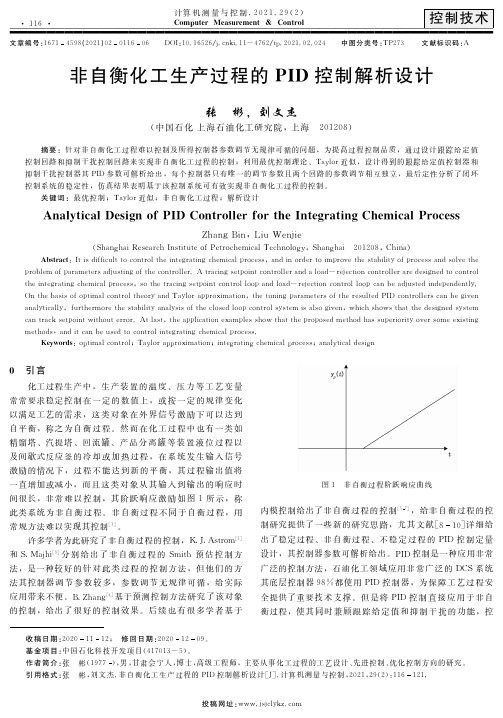
关键词:最优控制;Taylor近似;非自衡化工过程;解析设计犃狀犪犾狔狋犻犮犪犾犇犲狊犻犵狀狅犳犘犐犇犆狅狀狋狉狅犾犾犲狉犳狅狉狋犺犲犐狀狋犲犵狉犪狋犻狀犵犆犺犲犿犻犮犪犾犘狉狅犮犲狊狊ZhangBin,LiuWenjie(ShanghaiResearchInstituteofPetrochemicalTechnology,Shanghai 201208,China)犃犫狊狋狉犪犮狋:Itisdifficulttocontroltheintegratingchemicalprocess,andinordertoimprovethestabilityofprocessandsolvetheproblemofparametersadjustingofthecontroller.Atracingsetpointcontrollerandaload-rejectioncontrolleraredesignedtocontroltheintegratingchemicalprocess,sothetracingsetpointcontrolloopandload-rejectioncontrolloopcanbeadjustedindependently.OnthebasisofoptimalcontroltheoryandTaylorapproximation,thetuningparametersoftheresultedPIDcontrollerscanbegivenanalytically,furthermorethestabilityanalysisoftheclosedloopcontrolsystemisalsogiven,whichshowsthatthedesignedsystemcantracksetpointwithouterror.Atlast,theapplicationexamplesshowthattheproposedmethodhassuperiorityoversomeexistingmethods,anditcanbeusedtocontrolintegratingchemicalprocess.犓犲狔狑狅狉犱狊:optimalcontrol;Taylorapproximation;integratingchemicalprocess;analyticaldesign0 引言化工过程生产中,生产装置的温度、压力等工艺变量常常要求稳定控制在一定的数值上,或按一定的规律变化以满足工艺的需求,这类对象在外界信号激励下可以达到自平衡,称之为自衡过程。
- 1、下载文档前请自行甄别文档内容的完整性,平台不提供额外的编辑、内容补充、找答案等附加服务。
- 2、"仅部分预览"的文档,不可在线预览部分如存在完整性等问题,可反馈申请退款(可完整预览的文档不适用该条件!)。
- 3、如文档侵犯您的权益,请联系客服反馈,我们会尽快为您处理(人工客服工作时间:9:00-18:30)。
2018 年规模以上电子信息制造业增加值同比增长13.1%
据工业和信息化部2 月2 日消息,2018 年,我国电子信息制造业面对错综复杂的国内外形势,按照高质量发展要求,加快结构调整和转型升级,行
业运行呈现总体平稳、稳中有进态势,生产和投资增速在工业中保持领先,出
口平稳增长,在经济社会发展中的支撑引领作用进一步增强。
总体来看,2018 年,规模以上电子信息制造业增加值同比增长13.1%,快于全部规模以上工业增速6.9 个百分点。
12 月份同比增长10.5%。
规模以上电子信息制造业去年实现出口交货值同比增长9.8%,增速比2017 年回落4.4 个百分点。
12 月份同比增长2.0%。
2018 年,规模以上电子信息制造业主营业务收入同比增长9.0%,利润总额同比下降3.1%,主营收入利润率为4.51%,主营业务成本同比增长9.1%。
12 月末,全行业应收账款同比增长14.8%。
去年电子信息制造业生产者出厂价格同比下降1.4%。
12 月份同比增长0.4%,环比持平。
2018 年,电子信息制造业固定资产投资同比增长16.6%,高于制造业整体投资增速7.1 个百分点。
分行业来看,通信设备制造业方面,2018 年,通信设备制造业增加值同比增长13.8%,出口交货值同比增长12.6%。
主要产品中,手机产量同比下降4.1%,其中智能手机同比下降0.6%。
通信设备制造业主营业务收入同比增长9.6%,受上年基数较高等因素影响利润同比下降11.8%(2017 年为增长
38.0%)。
电子元件及电子专用材料制造业方面,2018 年,电子元件及电子专用材料制造业增加值同比增长13.2%,出口交货值同比增长14.0%。
主要产品中,电子元件产量同比增长12.0%。
电子元件及电子专用材料制造业主营业务收入同。