step 7 v5.5 中文版的帮助文档
(完整word)step7 5.5导入到WINCC画面中
WinCC STEP7 DB块中的变量如何直接导入WinCC变量表?1、从WinCC里调用STEP 7 变量的意义和前提条件2、在Simatic Manager里建立新的WinCC项目3、把现成的WinCC项目集成到STEP 7 项目中4、把变量(符号表,共享DB)从STEP 7传送到WinCC里5、在WinCC里直接调用STEP 7的符号表或共享DB块里的变量该文档的软件环境:Windows XP Professional SP1 EnglishWinCC V6。
0 SP2 HF2 EuropeSTEP 7 V5。
3 SP11、从WinCC里调用STEP 7 变量的前提条件从WinCC里调用STEP 7 变量可以将建立变量的工作量减少一半,同时将建立变量的出错概率建设一半,从而减少了相应的排错工作,大大提高了工作效率。
从WinCC里调用STEP 7 变量的前提条件是,WinCC的项目文件必须是集成在STEP 7项目中的。
在安装所有Simatic 软件前,请查阅软件的安装注意事项,确定操作系统与软件的兼容性.该文档一般位于:CD\Documents\〈语言版本〉\InstallNotes.chm。
要使用WinCC与STEP 7的集成功能,WinCC和STEP 7必须安装在同一台计算机上,必须在安装WinCC之前安装STEP 7。
STEP 7 与WinCC的版本必须一致.WinCC与STEP 7的版本兼容行列表可以在西门子自动化与驱动集团的技术支持与服务网站上获得。
请STEP 7安装完毕后,进行WinCC安装。
在WinCC安装过程中,请选择“自定义安装”,并且选中下图中红框标识的选件:图 1. 与集成相关的WinCC组件2、在Simatic Manager里建立新的WinCC项目在建立新的STEP 7项目后,可以在Simatic Manager里直接建立新的WinCC项目。
方法是在Simatic Manager里,右键点击项目名称,选择“Insert New Object\OS"。
西门子SIMATIC STEP7 V5.5 SP4配置指南说明书

How to configure SIMATIC STEP7 V5.5 SP4 to read acyclic data from MultiRanger/HydroRanger 200 HMI over SmartLinx PROFIBUS DPV1Application examples Introduction1 Overview2 Planning/configuring3Siemens AGGlobal Services Information Technology Document order number: AG090315Ⓟ 09/2020 Subject to changeCopyright © Siemens AG 2020.All rights reservedLegal informationWarning notice systemThis manual contains notices you have to observe in order to ensure your personal safety, as well as to preventdamage to property. The notices referring to your personal safety are highlighted in the manual by a safety alertsymbol, notices referring only to property damage have no safety alert symbol. These notices shown below aregraded according to the degree of danger.DANGERindicates that death or severe personal injury will result if proper precautions are not taken.WARNINGindicates that death or severe personal injury may result if proper precautions are not taken.CAUTIONindicates that minor personal injury can result if proper precautions are not taken.NOTICEindicates that property damage can result if proper precautions are not taken.If more than one degree of danger is present, the warning notice representing the highest degree of danger willbe used. A notice warning of injury to persons with a safety alert symbol may also include a warning relating toproperty damage.Qualified PersonnelThe product/system described in this documentation may be operated only by personnel qualified for the specifictask in accordance with the relevant documentation, in particular its warning notices and safety instructions.Qualified personnel are those who, based on their training and experience, are capable of identifying risks andavoiding potential hazards when working with these products/systems.Proper use of Siemens productsNote the following:WARNINGSiemens products may only be used for the applications described in the catalog and in the relevant technicaldocumentation. If products and components from other manufacturers are used, these must be recommendedor approved by Siemens. Proper transport, storage, installation, assembly, commissioning, operation andmaintenance are required to ensure that the products operate safely and without any problems. The permissibleambient conditions must be complied with. The information in the relevant documentation must be observed. TrademarksAll names identified by ® are registered trademarks of Siemens AG. The remaining trademarks in this publicationmay be trademarks whose use by third parties for their own purposes could violate the rights of the owner. Disclaimer of LiabilityWe have reviewed the contents of this publication to ensure consistency with the hardware and softwaredescribed. Since variance cannot be precluded entirely, we cannot guarantee full consistency. However, theinformation in this publication is reviewed regularly and any necessary corrections are included in subsequenteditions.Table of contents1 Introduction (4)1.1 Objective (4)1.2 Equipment (4)1.3 Disclaimer (4)2 Overview (5)3 Planning/configuring (6)3.1 Modifying GSD to perform acyclic communication (6)3.2 Slot index table (6)3.3 Adding MultiRanger/HydroRanger 200 HMI to the hardware configuration (7)3.4 Step7 example program (8)3.5 Slot index table (10)3.6 How to test using the VAT table (14)1.1ObjectiveThe objective of this application guide is to help the user become familiar with the stepsrequired to use acyclic communications through a SmartLinx PROFIBUS DPV1communications module to read/write data to MultiRanger/HydroRanger 200 HMI.1.2EquipmentNoteA complete code example is available for the Siemens SIMATIC S7300 PLC.This guide is an addition to the application guide Step7 V5.5 SP4 MR_HR _HMI. Please usethe Step7 V5.5 SP4 MR_HR _HMI application guide to setup the cyclic data before using thisguide.This guide assumes the user is familiar with Step V5.5 SP4.1.3DisclaimerNoteWhile every effort is made to verify the following information, no warranty of accuracy orusability is expressed or implied.All names identified by ® are registered trademarks of Siemens AG. The remaining trademarksin this publication may be trademarks whose use by third parties for their own purposescould violate the rights of the owner.This application guide is an addition to the operating instructions forMultiRanger/HydroRanger 200 HMI. It focuses on the setup and configuration of the S7300, using specific functions in the PLC, SFC58 (WR_REC), and SFC59 (RD_REC), to access the MultiRanger/HydroRanger 200 HMI parameters.Acyclic communication through PROFIBUS DPV1 is designed to allow read/write access to the PROFIBUS slave device. During normal operation of a PROFIBUS network, data is exchanged cyclically between the master and slave devices. If an acyclic request occurs, the Class I master will pass the request to the slave device. After the cyclic data has been read from the slaves, the acyclic request is sent to the slave. The slave device will then process the request and respond in the current scan or the next scan. Acyclic requests are executed periodically because parameter data is not required as frequently as the cyclic data.The example below will show you how to read/write the quick start parameters in MultiRanger/HydroRanger 200 HMI. The PLC code example uses a timer interrupt, OB35 (TIMER_INTERUPT), to indirectly call SFC58 and SFC59. In this example, OB35 is executed every 100 ms.Planning/configuring 3 3.1Modifying GSD to perform acyclic communication1.To allow acyclic communications through a Class I master, you must change the C1 and C2response timeout.2.Open the GSD file, HMSB1813.gsd, in Notepad and change the C1 and C2 timeout as shownbelow.Save the file.Use this GSD file to configure hardware in Step7.3.2Slot index tableThe parameters, or diagnostic information, in the PROFIBUS slave device are arranged in astandard way and are accessed through the slot index table. The table defines whereinformation is stored in the device and references the slot and index for a parameter ordiagnostic.3.3 Adding MultiRanger/HydroRanger 200 HMI to the hardware configuration 3.3Adding MultiRanger/HydroRanger 200 HMI to the hardwareconfigurationTo add the MultiRanger/HydroRanger 200 HMI to the hardware configuration, you will needto add the device to the network and define the number of modules required. A moduleholds a group of parameters or diagnostic information for the device. The total number ofmodules must match the number of modules in the slot index table. The number of bytes ineach module must add up to the total number of bytes used for cyclic data exchange. For theMultiRanger/HydroRanger 200 HMI, this is 19 words of input.In the Step7 hardware configuration you will see that 6 modules have been added forMultiRanger/HydroRanger 200 HMI.Slot/Module Description1 Parameters for channel 12 Parameters for channel 23 Global parameters4 Relays5 Device6 Echo profile (internal use)NoteThe number of modules used in the cyclic data configuration is related to the number of slotsused for acyclic communications. Therefore, in order to access all 6 acyclic slots, 6 modulesmust be used in the hardware configuration.3.4 Step7 example program3.4Step7 example programThis example will show you how to read/write the quick start parameters for theMultiRanger/HydroRanger 200 HMI by referencing the index from the slot index table. In theslot index table, the quick start parameters for point 1 start at slot 1, index 50.1.In step7 V13, add OB35.2.Inside OB35, insert a network for SFC58 and SFC59. OB35 will execute every 100 ms andcall SFC58 and SFC59.3.Read the quick start parameters from the MultiRanger/HydroRanger 200 HMI and move thedata to DB1.If M100.1 is closed, SFC59 is called and will write the parameters from DB1 (Quick start 2) tothe MultiRanger/HydroRanger 200 HMI.The complete code for OB35 is shown below:3.4 Step7 example program SFC59 (RD_REC) parametersREQ Start the requestIOID Module typeLADDR Address of the module1: 256 (0 x 100)RECNUM Index: 50 (0 x 32)P#DB1.DBX0.0 Data block holding the result of the parameter readBUSY Function statusRET_VAL Result of the functionSFC58 (WR_REC) parametersSome additional logic is used to disable the RD_REC while the RD_WRI is being executed. REQ Start the requestIOID Module typeLADDR Address of the module 1: 256 (0x100)RECNUM Index: 50 (0x32)P#DB1.DBX12.0 Data block where data will be read from and sent to MultiRanger/HydroRanger200 HMIBUSY Function statusRET_VAL Result of the function3.5 Slot index tableEnabling M100.0 will initiate a RD_REC if a RD_WRI is not being executed.Enabling M100.2 will initiate a RD_WRI and disable a RD_REC while the RD_WRI is beingperformed. When the WR_REC is complete, M100.2 will be cleared to disable the WR_REC call.Refer to the slot index table below for the data type for each parameter. If you are writingto the MultiRanger/HydroRanger 200 HMI, enter the data into the data structure inDB1.DBX12.0 (Quick start 2).3.5Slot index table3.5 Slot index table3.5 Slot index table3.5 Slot index table3.6 How to test using the VAT table3.6How to test using the VAT table1.Create a VAT table to test the read/write function.e M100.2 to enable the WR_REC and send the Quick start 2 to theMultiRanger/HydroRanger 200.。
step7 v5.5cn

SIMATIC用于SIMATIC S7 / M7 / C7的STEP 7 V5.5编程软件安装与使用注意事项该注意事项中包含的信息相对于其它文档来说是最新的。
请仔细阅读,此文本中包含了有关STEP 7 V5.5的安装与使用信息。
对该版本的重要修订以斜体显示,并标有注释“从该版本开始新增的内容”。
请注意,对于A4格式,所要打印文件的左右边距都设置成25 mm。
目录安装注意事项1发货清单2硬件要求3软件要求3.1运行环境3.2需要的存储空间3.3与其它软件产品的兼容性3.3.1Rational ClearCase配置管理工具3.3.2使用其它软件产品时的网络设置3.4在线文档4安装4.1安装STEP 7 V5.54.2升级旧版STEP 74.3STEP 7 V5.5许可证密钥4.4删除STEP 7 V5.54.5安装时的其它注意事项4.5.1使用滚轮鼠标4.5.2使用PC/PG通信卡时的注意事项使用注意事项(版本注释)5新版软件的新特性和所作的修改6组态和操作软件时的注意事项6.1STEP 7如何满足IEC标准6.2常规注意事项6.3使用网络驱动器6.4多用户操作6.5多重项目6.6交换不同版本的STEP 76.7库文件和实例项目6.8SIMATIC管理器6.9使用符号名6.10硬件配置(中央机架)6.11硬件配置(PROFIBUS DP)6.12硬件配置(PROFINET IO)6.13冗余I/O:通道间隔冗余6.14硬件诊断6.15MPI / PROFIBUS网络设置6.16SIMATIC M76.17梯形图、功能块图、语句表和参考数据6.18翻译文本6.19管理多语言文本6.20将S5程序转换成S7程序6.21将TI程序转换成S7程序6.22容错系统6.23使用外文字符集时的注意事项6.24使用SIMATIC Logon的注意事项6.25命令接口6.26TCI –工具调用接口6.27MS Windows 7操作系统的特性7文档注意事项8使用STEP 7中文版时的重要特性安装注意事项本注意事项中包含您在安装STEP 7 V5.5时所需的重要信息,在安装该软件以前请务必详细阅读该注意事项。
STEP7-功能块全中文说明全解课件.doc
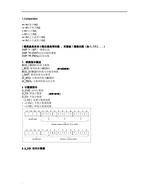
parator== IN1等于IN2<> IN1不等于IN2> IN1大于IN2< IN1小于IN2>= IN1大于或等于IN2<= IN1小于或等于IN22.整数就是没有小数位都是零的数,即能被1整除的数(如-1,-2,0,1,……)CMP ?I(INT)整数比较CMP ?D (DINT)比较双精度整数CMP ?R (REAL)比较实数3.转换指令概述BCD_I BCD码转换为整数I_BCD 整型转换为BCD码[新^&版@版新]BCD_DI BCD码转换为双精度整数I_DINT 整型转换为长整型DI_BCD 长整型转换为BCD码DI_REAL 长整型转换为浮点型4 计数器指令S_CUD 双向计数器S_CD 降值计数器[新版^@%*新]S_CU 升值计数器---( SC ) 设置计数器线圈•---( CU ) 升值计数器线圈•---( CD ) 降值计数器线圈5.S_CUD 双向计数器`6. S_CU 升值计数器7. S_CD 降值计数器8. ---( SC ) 设置计数器值9. ---( CU ) 升值计数器线圈[新新&@^#版]10. ---( CD ) 降值计数器线圈11. ---(OPN)打开数据块:DB或DI如果想将数据块中的数据读出(如DB和DI),需要通过(OPN)打开数据块后才可读出。
12. ---(JMP)--- 无条件跳转13. ---(JMPN) 若“否”则跳转14. LABEL标号【整型数学运算指令】整型数学运算指令概述[新*新^版@版]说明使用整数运算,您可以对两个整数(16和32位)执行以下运算:•ADD_I 加整数•SUB_I 减整型•MUL_I 乘整型•DIV_I 除整型•ADD_DI 加双精度整数•SUB_DI 减长整型•MUL_DI 乘长整型•DIV_DI 除长整型•MOD_DI 返回分数长整型15. ADD_I 整数加16. SUB_I 整数减17. MUL_I 整数乘[新版版@#&新]18. DIV_I 整数除[新版%^@&~]19. MOD_DI 返回长整数余数20. 浮点运算指令概述IEEE32位浮点数属于REAL数据类型。
Step7v55CN中文版及PLCSIM仿真器下载安装步骤详解
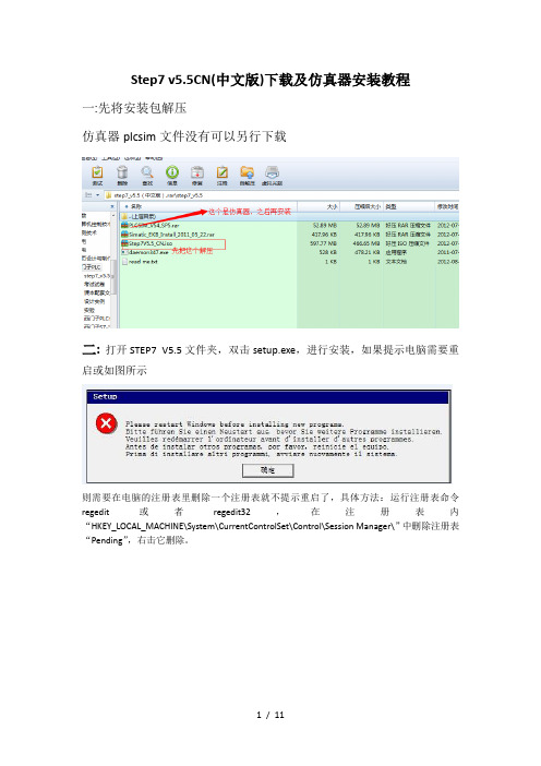
Step7 v5.5CN(中文版)下载及仿真器安装教程一:先将安装包解压仿真器plcsim文件没有可以另行下载二:打开STEP7 V5.5文件夹,双击setup.exe,进行安装,如果提示电脑需要重启或如图所示则需要在电脑的注册表里删除一个注册表就不提示重启了,具体方法:运行注册表命令regedit或者regedit32,在注册表内“HKEY_LOCAL_MACHINE\System\CurrentControlSet\Control\Session Manager\”中删除注册表“Pending”,右击它删除。
三、双击setup.exe之后,选择安装简体中文,如图下一步。
四、下一步选择接受,再下一步。
五、程序进入安装状态,大概会花费十几分钟。
进入逐个程序安装,到这里选择下一步。
在此选择典型安装,您可以选择安装到其他磁盘,下一步。
选择简体中文,下一步在此点击安装,程序会继续进行安装。
这里需要几分钟出现这个窗口点击PC Adapter然后安装,关闭选择立即重启电脑,重启完后再授权。
重启后电脑桌面上会多三个图标接下来对软件授权Windows 7:打开安装包中的这个文件完成上面三步点击ALL,完成即可下面是仿真器的安装,安装包中PLCSIM_V54_SP5这个文件仿真安装包,需要注意的是,安装时需将这个文件拷贝在之前step7安装路径下,找到common files 这个文件将文件拷贝在下面这个文件里打开安装之前先检查,之前这个注册表是否被删除,因为电脑重启后此文件将恢复,须重新删除再进行安装删除后即可安装安装完成后,打开step7软件,会发现下面这个图标由灰变亮了,表示可以使用仿真器可模拟接口关闭11 / 11。
STEP 7 V5.5 中文版已供货发布

l MS Windows 7 Multilingual User Interface Pack (MUI) 32 Bit 但是,Windows 7 下的 Windows XP 模式尚未发布。
请注意: 所有操作系统都需要安装 Microsoft Internet Explorer 6.0 (或更高版本)。 PDF 文件的显示:要能够阅读所含的 PDF 文件,需要兼容 PDF 1.7 的 PDF 阅读器 (ISO32000-1:2008 PDF)。 除了 STEP 7,STEP 7 DVD 还包含下列程序,这些程序的安装文件位于目录 CD2\Optional Components 中: S7 Block Privacy,用于对软件块加密 S7 Web2PLC,用于将用户定义的网站集成到 CPU 中 有关详情,请参见自述文件
STEP 7 V5.5 中文版供货发布 概要
STEP 7 V5.5 中文版已供货发布。STEP 7 用户可通过购买升级包将现有 STEP 7 软件升级到最新版本 (订货号 6ES7810-4CC10-0KE5)。
互联网文件
内容:
1. STEP 7 V5.5 的订货信息 2. 系统要求 3. STEP 7 V5.5 的新功能 4. STEP 7 V5.4 - 产品淘汰 5. STEP 7 V5.3 - 产品停产
STEP 7 V5.5 中文版升级包: 已拥有 STEP 7 V3.x、V4.x、V5.0、V5.1、V5.2、V5.3 或 V5.4 的客户可购买升级包。安装升级包的前 提是具有 STEP 7 V3.x、V4.x、V5.0、V5.1、V5.2、V5.3 或 V5.4 的有效许可。
概述: STEP 7 V5.5 中文版以 DVD 形式提供,许可秘钥位于 USB 存储棒中。STEP 7 中文版支持中文和英 文。 当从 5 种语言版本的 STEP 7 切换到 STEP 7 V5.5 中文版时,应注意下列事项: 安装 STEP 7 V5.5 中文版前,必须卸载 STEP 7 和其它已安装的选项包。安装 STEP 7 V5.5 中文版 后,可像通常一样安装任何所需的中文和英文版本的选项包。不支持中文的选项包只能运行在英语模式 下。5 种语言版本的 STEP 7 V5.5 和 STEP 7 V5.5 中文版的许可证都一样。 文档:
STEP7-功能块全中文说明全解课件.doc
parator== IN1等于IN2<> IN1不等于IN2> IN1大于IN2< IN1小于IN2>= IN1大于或等于IN2<= IN1小于或等于IN22.整数就是没有小数位都是零的数,即能被1整除的数(如-1,-2,0,1,……)CMP ?I(INT)整数比较CMP ?D (DINT)比较双精度整数CMP ?R (REAL)比较实数3.转换指令概述BCD_I BCD码转换为整数I_BCD 整型转换为BCD码[新^&版@版新]BCD_DI BCD码转换为双精度整数I_DINT 整型转换为长整型DI_BCD 长整型转换为BCD码DI_REAL 长整型转换为浮点型4 计数器指令S_CUD 双向计数器S_CD 降值计数器[新版^@%*新]S_CU 升值计数器---( SC ) 设置计数器线圈•---( CU ) 升值计数器线圈•---( CD ) 降值计数器线圈5.S_CUD 双向计数器`6. S_CU 升值计数器7. S_CD 降值计数器8. ---( SC ) 设置计数器值9. ---( CU ) 升值计数器线圈[新新&@^#版]10. ---( CD ) 降值计数器线圈11. ---(OPN)打开数据块:DB或DI如果想将数据块中的数据读出(如DB和DI),需要通过(OPN)打开数据块后才可读出。
12. ---(JMP)--- 无条件跳转13. ---(JMPN) 若“否”则跳转14. LABEL标号【整型数学运算指令】整型数学运算指令概述[新*新^版@版]说明使用整数运算,您可以对两个整数(16和32位)执行以下运算:•ADD_I 加整数•SUB_I 减整型•MUL_I 乘整型•DIV_I 除整型•ADD_DI 加双精度整数•SUB_DI 减长整型•MUL_DI 乘长整型•DIV_DI 除长整型•MOD_DI 返回分数长整型15. ADD_I 整数加16. SUB_I 整数减17. MUL_I 整数乘[新版版@#&新]18. DIV_I 整数除[新版%^@&~]19. MOD_DI 返回长整数余数20. 浮点运算指令概述IEEE32位浮点数属于REAL数据类型。
step7安装解决
