MotorSys 智能配电及马达控制中心
发电机的智能化控制与远程管理说明书
发电机的智能化控制与远程管理说明书说明书概述:本说明书旨在介绍发电机的智能化控制与远程管理的方法和步骤,以提高发电机的运行效率和管理便捷性。
本文将从智能化控制系统的组成、远程管理平台的功能、操作步骤及注意事项等方面进行详细说明。
一、智能化控制系统的组成1. 控制器:发电机智能化控制系统的核心部件,具有数据采集、处理和控制功能。
2. 传感器:用于采集发电机的运行状态数据,如电流、电压、温度等。
3. 人机界面:为用户提供与发电机智能控制系统交互的界面,使用户可以实时监控和操作发电机。
4. 通信模块:负责与远程管理平台进行数据传输和通信,实现远程监控和控制。
二、远程管理平台的功能1. 远程监控:通过远程管理平台,用户可以实时监测发电机的运行状态和性能参数。
2. 远程控制:用户可以通过远程管理平台对发电机进行远程开启、关闭及调整参数等操作。
3. 数据分析:远程管理平台将采集到的大量数据进行分析和统计,生成运行报告和故障诊断结果。
4. 预警与维护:远程管理平台可设置预警机制,对发电机的异常情况进行实时提醒,以便及时维护和修复。
三、操作步骤及注意事项1. 确保控制器与传感器的正常连接,并进行必要的参数配置。
2. 打开人机界面,登录远程管理平台账号。
3. 在远程管理平台的主界面中,可以看到当前发电机的各项数据和运行状态。
4. 如需对发电机进行操作,可点击相应按钮进行开启、关闭或参数调整。
5. 在远程管理平台上,用户可以进行数据分析和故障诊断,得出相应的运行报告和修复方案。
6. 注意定期检查传感器和控制器的工作状态,并做好数据备份和安全防护措施。
总结:随着科技的发展,发电机的智能化控制与远程管理将成为未来发电行业的发展趋势。
本说明书详细介绍了发电机智能化控制系统的组成,以及远程管理平台的功能和操作步骤。
希望本文能够对用户理解和应用发电机的智能化控制与远程管理提供帮助,提高发电机的运行效率和管理便捷性。
如果对于发电机的智能化控制和远程管理还有任何疑问,请与我们联系。
智能电机的原理及应用

智能电机的原理及应用1. 智能电机的概述智能电机是指具备自主学习、感知环境、智能决策和自动控制等功能的电机。
随着人工智能和物联网的发展,智能电机已经在各个领域得到广泛应用,并取得了显著的成果。
智能电机通过内部的传感器和控制系统,可以根据外部环境和任务需求自动调整转速、扭矩等参数,以实现更加精确、高效的运动控制。
2. 智能电机的工作原理智能电机通常由电机驱动器、传感器、控制器和通信模块等组成。
其中,电机驱动器负责向电机提供所需的电流和电压,传感器用于感知电机运行状态和周围环境的变化,控制器则根据传感器数据和预设的控制算法来实现对电机的智能控制。
传感器可以包括位置传感器、速度传感器、负载传感器等,它们能够实时监测电机的运行状态,例如转子位置、转速、负载情况等。
控制器通过分析传感器数据,并结合预设的控制算法,可以动态调整电机的转速、扭矩和运动轨迹等参数。
智能电机的通信模块可以使其与其他智能设备或网络进行数据交互,实现远程监控和控制。
例如,智能电机可以通过与工厂的物联网系统连接,实现远程监控和远程维护,提高生产效率和安全性。
3. 智能电机的应用领域智能电机的应用领域非常广泛,下面列举了一些主要的应用领域:•工业自动化:智能电机可以广泛应用于工业生产线上的各种机械设备,如输送带、机器人等。
通过智能电机的精确控制,可以提高生产效率和产品质量,减少能源消耗和人员安全风险。
•家居智能化:智能电机可以应用于家居中的窗帘、卷闸门、风扇、空调等设备,实现远程控制和自动调节。
用户可以通过手机APP或语音指令控制这些设备,提高生活的便利性和舒适度。
•智能交通:智能电机可以应用于电动车、无人驾驶车辆等交通工具中,实现精确的车速控制和动力调节,提高行驶安全和舒适性。
•医疗器械:智能电机可以应用于医疗器械中,如手术机械、呼吸器等。
通过智能电机的精确控制,可以提高手术的准确性和安全性,改善病人的生活质量。
•机器人技术:智能电机是机器人技术中不可或缺的一部分。
智能MCC控制中心

智能MCC控制中心一.概述电机控制中心:又称马达控制中心、电动机控制中心,英文名称为MOTOR CONTROL CENTER,简称MCC。
电机控制中心统一管理配电和仪器设备,将各种电机控制单元、馈电线接头单元、配电变压器、照明配电盘、联锁继电器以及计量设备装入一个整体安装的机壳内并且由一个公共的封闭母线供电。
传统电机控制中心(CMCC):传统电机控制中心(CMCC)可以实现电机的起、停控制和简单的故障检测,性能可靠,利于维护,广泛应用于国民经济的各个领域,尤其是石油化工、冶金、造纸、建材、纺织、食品加工、制药、电力等需要过程控制的领域。
智能电机控制中心(IMCC):智能电机控制中心(IMCC)功能强大,可以提供电机位置和速度伺服控制功能,多种电机故障检测和诊断功能,广泛应用于复杂的过程控制中。
CMCC和IMCC既可以单独使用完成电机控制.又可以作为分散控制系统DCS或者可编程逻辑控制器PLC的现场执行器,与之共同完成控制任务,是工厂自动化的关键设备。
多角色操作智能型电动机保护与控制器,作为智能MCC控制中心的核心器件,在智能MCC控制中心中起着关键的作用。
智能型电动机保护与控制器带有:过载、过压、欠载、堵转、断相多种电机故障检测和诊断功能;带有全压起动、星三角起动、双向起动、双速起动等多种控制功能;带有通讯功能,方便组网,利于集中控制;带有电流、电压、功率、温度等多种测量功能;带有模拟量输出功能。
智能型电动机保护与控制器国外知名品牌有:西门子SIMOCODE pro,施耐德TeSys T、TeSys U;国内品牌有:ACREL的ARD,苏州万龙ST500,保定尤耐特UNT-MMI等。
下面以ACREL的ARD系列产品为例,介绍低压马达控制与保护器。
二.适用环境工作温度:-10ºC~55ºC存储温度:-25ºC~70ºC相对湿度:≤95%不结露海拔高度:≤2000m三.电磁兼容静电抗干扰实验Ⅲ级(IEC61000-4-2)辐射抗干扰试验Ⅲ级(IEC61000-4-3)电快速瞬变脉冲群干扰试验Ⅳ级(IEC61000-4-4)浪涌抗干扰试验Ⅳ级(IEC61000-4-5)射频传导干扰试验Ⅲ级(IEC61000-4-6)电磁场抗干扰试验Ⅲ级(IEC61000-4-8)四.功能测量功能:电流参数、电压、功率、相序、剩余电流(接地/漏电流)。
智能低压配电系统研究发展现状【可编辑全文】

可编辑修改精选全文完整版智能低压配电系统研究发展现状智能配电系统、电气火灾监控系统、环境监控系统、火灾监控其智能化发展较晚而且相互独立,很少有将这些监控功能综合运用到智能配电系统中的配电系统。
国内配电系统智能化研究较晚,自上个世纪90年达才刚起步,而目前我国的低压配电系统虽然采用了目前我国的低压智能设备在技术上虽然采用了微处理器技术,但很少能开发生产国际先进技术水平的低压智能设备,只有一些全数字的设备。
对于智能低压配电系统所应用的各种先进技术(计算机技术、网络通讯技术等)也落后于发达国家,目前国内对于部分技术的技术核心仍是从国外引进,缺少专业技术人员提供更可靠的技术支持。
电气火灾监控系统目前不论是国内还是国外的研究都处于将其独立与其他监控系统,虽然有运用到配电系统当中,当其智能化程度均不高,国内从10前才刚研究,虽然有了较大的进步,但是缺点明显(报警阈值设定依靠人工判断)没有很好的结合其他监控系统(如环境监控)去智能设置报警阈值。
鉴于目前的研究现状,需要大力发展智能化技术,并将它们运用到配电系统当中,能有效的保障配电系统运行安全。
国内目前对于配电综合控制(管理)系统的研究处于将几个监控系统功能上的结合,没有很好的综合控制策略去实现动态的控制。
比如在配电房安装视频监控系统和温湿度监测系统,并将它们通过网络通讯服务连接到监控主机上,虽然这样的系统满足了综合管理方面的一些需求,但是缺少智能控制策略去实现因各种变化时的所需要的管理方案,都是依靠人工去判别。
其功能上依然处理独立状态。
2.国内外智能化发展现状在智能元件和智能系统方面:与国外相比国内在智能低压配电系统的研究起步比较晚。
智能元件方面,从1985年到1987年,国内首先抛弃了原先的充气式时间继电器和电流继电器,开始开发自耦减压起动柜。
1989~1990年电子类型的电动机保护器问世,1991~1992年期间半导体类型的热继电器也相继问世。
在整套设备上面,智能类型的配电系统成为现在研究最集中的地方,为了能够采集数据,马达控制中心被开发出来,由上位机监控低压柜运行时的状态并集中处理和排查故障,低压系统的安全性和可靠性又得到了进一步的升级。
智能电机控制器课程设计

智能电机控制器课程设计一、课程目标知识目标:1. 让学生理解智能电机控制器的基本原理与结构,掌握其工作流程。
2. 使学生掌握电机控制相关参数的计算方法,并能运用这些方法优化电机控制性能。
3. 帮助学生了解智能电机控制器在不同应用场景中的选型和应用要求。
技能目标:1. 培养学生运用所学知识进行智能电机控制器电路设计与分析的能力。
2. 提高学生动手实践能力,使其能够独立完成智能电机控制器的组装与调试。
3. 培养学生团队协作和沟通能力,能够就电机控制问题进行讨论和分析。
情感态度价值观目标:1. 激发学生对电机控制技术的兴趣,培养其创新意识和探索精神。
2. 引导学生关注智能电机控制器在节能减排、环境保护等方面的应用,提高环保意识。
3. 培养学生严谨的学习态度,使其认识到理论知识与实际应用相结合的重要性。
课程性质:本课程为实践性较强的学科,要求学生将理论知识与实际操作相结合,通过课程学习,提高解决实际问题的能力。
学生特点:学生具备一定的电子技术基础知识,具有较强的学习兴趣和动手欲望,但对电机控制相关知识的掌握有限。
教学要求:结合学生特点,注重理论与实践相结合,以项目驱动教学,培养学生动手实践能力和团队协作能力,提高其知识水平和技能素质。
通过本课程的学习,使学生能够达到上述课程目标,为未来从事电机控制相关领域工作打下坚实基础。
二、教学内容1. 智能电机控制器原理与结构- 电机控制基本原理- 智能电机控制器组成与功能- 常见智能电机控制器类型及特点2. 电机控制参数计算与性能优化- 电机控制参数的含义与计算方法- 控制参数对电机性能的影响- 性能优化方法及案例分析3. 智能电机控制器选型与应用- 不同场景下的电机控制器选型依据- 智能电机控制器在典型应用中的连接与调试- 应用案例分析与讨论4. 智能电机控制器电路设计与实践- 电机控制器电路设计方法与步骤- 常用电机控制器电路元器件的选用与连接- 实践项目:智能电机控制器组装与调试5. 教学进度与安排- 原理与结构:2课时- 参数计算与性能优化:3课时- 选型与应用:2课时- 电路设计与实践:3课时教学内容根据课程目标进行选择和组织,注重科学性和系统性。
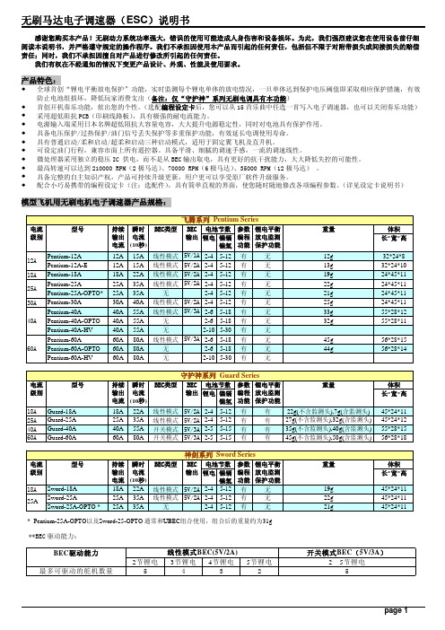
无刷马达电子调速器(ESC)说明书
感谢您购买本产品!无刷动力系统功率强大,错误的使用可能造成人身伤害和设备损坏。
为此,我们强烈建议您在使用设备前仔细阅读本说明书,并严格遵守规定的操作程序。
我们不承担因使用本产品而引起的任何责任,包括但不限于对附带损失或间接损失的赔偿责任;同时,我们不承担因擅自对产品进行修改所引起的任何责任。
我们有权在不经通知的情况下变更产品设计、外观、性能及使用要求。
产品特色:全球首创“锂电平衡放电保护”功能,实时监测每个锂电单体的放电情况,一旦单体达到保护电压阈值即采取相应保护措施,有效防止电池组损坏,降低玩家消费支出(备注:仅“守护神”系列无刷电调具有本功能)首创开机奏乐功能,炫出您的个性。
(选配编程设定卡后,您可以从15首乐曲中任选一首写入电子调速器,也可以关闭奏乐功能) 采用超低阻抗PCB(印刷线路板),具有极强的耐电流能力。
电源输入端采用日本名牌超低阻抗大容量电容,大大提升电源稳定性,同时对电池具有保护作用。
具备电压保护/过热保护/油门信号丢失保护等多重保护功能,有效延长电调使用寿命。
具有普通启动/柔和启动/超柔和启动三种启动模式,适用于固定翼飞机及直升机。
可设定油门行程,兼容市面上所有遥控器。
具备平滑、细腻的调速手感,一流的调速线性。
微处理器采用独立的稳压IC 供电,而不是从BEC输出取电,具有更好的抗干扰能力,大大降低失控的可能性。
最高转速可以达到210000 RPM(2极马达)、70000 RPM(6极马达)、35000 RPM(12极马达) 。
具备完整的自主知识产权,产品可持续升级更新,用户更可以享受原厂软件升级服务。
配合小巧易携带的编程设定卡(注:选配件),具有简单直观的界面,使您随时随地修改各项编程参数。
(详见设定卡说明书)模型飞机用无刷电机电子调速器产品规格:**BEC驱动能力:接线示意图:锂电平衡放电监测保护接头示意图:各个厂家推出的锂电池配备有不同的平衡充电接口,因此我们提供了两种平衡放电监测保护接头供用户选用: 平衡放电监测保护接头(类型一): 平衡放电监测保护接头(类型二):适用于台湾亚拓等品牌锂电池 适用于Polyquest、E-tec、Thunder Power 等品牌锂电池产品功能简要说明:1. 刹车设定:无刹车/有刹车,出厂默认值为无刹车。
Okken高可靠性智能低压成套柜-中文样本SCDOC379

高可靠性智能低压成套解决方案
关于施耐德电气
施耐德电气是全球能效管理和自动化领域的专家,致力于为客户提供安全、可靠、高效、经济以及环保的能源和过程管理。 集团 2016 财年销售额为 247 亿欧元,在全球 100 多个国家拥有 16 万名员工。从最简单的开关产品到复杂的运营系统, 我们的技术、软件和服务帮助客户管理和优化运营,通过互联互通的科技助力产业优化,改善城市生态,丰富人们的生活。
应用实例
20
技术补充说明
41
1
行业应用
2
行业应用
客户需求与解决方案
石油、天然气、 石油化工
矿山、冶金、水泥
大型公用建筑
客户需求 解决方案
供电连续性和安全性
> 智能化电机控制和配电系统 > 高可靠性 > 故障后快速重启 > 内燃弧防护 > 壳牌石油DEP标准认证
环境耐受力和供电安全性
供电连续性
> 导电部件的特殊防腐蚀处理 >IP54防护等级,确保部件能够用
业绩覆盖不同领域:
中海油珠海LNG项目 伊拉克哈法亚气管线项目 罗盖特精细化工 大庆宏伟园区15万吨/年丙烯项目 中海油莆田仙游应急抢修中心 广西南宁机场 福建三明沙县机场工程 郑州新郑机场T2航站楼扩建项目
京东方合肥8代线 中科电航空电子成都产业园 深圳赛意法电子 东吴证券总部大楼 广州白天鹅宾馆 昆明地铁3号线 深圳地铁9,11号线 岭澳核电站
机械参数 电缆进出 接线方式 防护等级 (IP) 防撞等级 (IK) 分隔形式 连接形式 尺寸 (mm)
平均重量 外壳表面喷涂 柜体颜色
高度 宽度
深度
顶部/底部 前面/后面 22 / 31 / 40 / 41 / 42 / 54 10 2b / 3b / 4a / 4b FFD / WFD / WFW / WWW 2200 / 2350 600 / 650 / 800 / 900 1000 / 1100 / 1150 / 1300 600 / 1000 / 1200 / 1400 650 kg 聚合环氧树脂/聚酯粉末(SP03),> 50 μ数
施耐德电气 SMC-2 智能电机控制器说明书

OverviewBulletin 150 — Smart Motor Controllers — SMC-2™The SMC-2™ Controller is a compact, multi-functional, versatile solid-state controller used in starting standard three-phase squirrel-cage induction motors. Three standard modes of operation are available within a single controller:Standards Compliance/Approvalsy CE Marked (Open Type) Per Low Voltage Directive 73/23/EEC, 93/68/EEC y CSA Certified (Open Type) (File No. LR1234)y UL Listed (Open Type) (File No. E96956, Guide No. NMFT)Your order must include 1) cat. no. of the controller selected, 2) if required, suffix code and description of any modifications, and 3) if required, cat. no. of any options or accessories.Series ControllerThe SMC-2 Controller is designed to operate in series with an electromechanical motor starter. The series mode has the following features:y Eliminates the need for additional control wiring, simplifying initial installation.y Works in unison with an existing electromechanical motor starter for easy retrofits.y Allows easy set-up with digital adjustments eliminating the guesswork of setting analog potentiometers.Controller with Interface Optiony Soft Starty Current Limit Start y Full Voltage Starty Optional Soft Stop (Requires Interface Module)The SMC-2™ Controller is available in eight sizes: 5, 9, 16, 24, 35, 54,68, and 97 A. It is offered in three voltage ranges: 200…230V ,380…460V , and 500…575V , 50/60 Hz.The SMC-2™ Controller can be used in two configurations: as a series controller and as a motor controller with an interface option.Table of ContentsCat. No. Explanation 6-37Product Selection . . .6-38Accessories . . . . . . . . .6-41Options . . . . . . . . . . . . .6-41Specifications . . . . . . .6-42ApproximateDimensions . . . . . . . . .6-43Enclosed Options . . .6-68The SMC-2 Controller with the interface option is designed so it can be operated without an electromechanical motor starter. The SMC-2Controller with the interface option offers the following features:y Provides ON/OFF control directly to the controller through an external pilot device. In many applications the interface option may eliminate the need for an additional contactor if electrical isolation or soft stop is not required. This reduces panel space requirements.y Provides a selectable auxiliary contact, which operates as either an instantaneous or up-to-speed contact, making it available for a wide variety of control schemes.y Provides a Soft Stop feature that extends stopping time to minimize load shifting or spillage during stopping.The interface option can be field or factory installed. For devices rated 5…16 A, this is a plug-in module. For devices rated 24…97A, there is a PC board that replaces the existing board.Energy SaverThis built-in feature of the SMC-2 Controller is used to save energy on applications where the motor is lightly loaded or unloaded for long periods of time.Protective ModuleIn applications where the SMC-2 Controller is exposed to high or abnormal line transients, an optional protective module is available and can be mounted on both the line and load side of the unit. The protective module contains MOVs (Metal Oxide Varistors) that protect the SCR from line surges and snubber networks to shunt noise energy away.Cat. No. ExplanationCombinationbController RatingsCode Amps Max Hp Max kW 200230460575220380415500W0551133 1.1 2.2 2.23W0992257-1/2 2.244 5.5W161635101047.57.57.5W242457-1/21520 5.5111115W3535101025301018.52222W54541520405015223037W68682025506018.5333745W97973030757525455563Open and Non-CombinationaBulletin NumberCode Description150Solid-State ControllerbController Ratings Code Amps Max Hp Max kW200230460575220380415500A0551133 1.1 2.2 2.23A0992257-1/2 2.244 5.5A161635101047.57.57.5A242457-1/21520 5.5111115A3535101025301018.52222A54541520405015223037A68682025506018.5333745A97973030757525455563cEnclosure TypeCode Description N OpenF NEMA Type 4 (IP65)JNEMA Type 12dInput Line VoltageCode DescriptionA 200…230V AC (+10%,–15%), 50 and 60 Hz,3-phaseB 380…460V AC (+10%,–15%), 50 and 60 Hz,3-phaseC 500…575+10%, –15%), 50and 60 Hz,3-phaseaBulletin NumberCode Description152CCombination Solid-State Reduced Voltage Controller with Fusible Disconnect and Isolation Contactor 152XCombination Solid-State Reduced Voltage Controller with FusibleDisconnect, 120V Interface Module and Control Circuit Transformer, withoutIsolation ContactorcEnclosure TypeCode Description F NEMA Type 4 (IP65)JNEMA Type 12 (IP64)150–A05NB –D1–8L4–NA –7a bcde f g h152C –W05JBD –D1–ND –8L4abcdefg1IEC overload relays are rated for Class 10 operation.†Overload option for 5…16 A only (open type) and non-combination or combination unit (5…97 A units).‡Protective modules factory installed on 5…54 A units only. 68 and 97 A are field modifications only.§When an IEC overload relay is selected, protective modules are limited to line side only. (For 5…16 A rated controllers only.)♣Interface option provides selectable auxiliary contact and Soft Stop feature.®External overload reset available for 5…97 A rated controllers ordered as a non-combination or combination unit with an overload relay.a IEC overload relays are rated for Class 10 operation for 5…97 A rated controllers only. See Table “e”for IEC overload selection. For 24…97 A rated controllers, NEMA overloads are furnished as standard. Requires control power source.eOverload Relay Selection 1†Code Current Rating C10.32...1.0D1 1.0...2.9E1 1.6...5.0F1 3.7...12H112...32H212...38J214...45K323...75L466 (110)fProtective Modules ‡Line SideBoth Line andLoad230V AC 8L2230V AC 8B2§460V AC 8L4460V AC 8B4§575V AC 8L6575V AC 8B6§gInterface Option ♣Code NANDControl Voltage200…240V (+10%, –15%),50 and 60 Hz, single-phase 100…120V (+10%, –15%),50 and 60 Hz, single-phasehExternal Reset ®Code 7DescriptionFor NEMA Type 4 (IP65) or NEMA Type 12 (IP64)For a listing of availableoptions, please see page 6-68dInput Line VoltageAC LineVoltage 200208230400460500575Hz50606050605060Common H H A I B M C Control Wiring Method Separate Control120V/60Hz Secondary —HD AD —BD —CD 110V/50Hz SecondaryHS ——NS —MS —eOverload Selection aCodeCurrent RatingSee table “e” above for detailsfInterface Option ♣CodeNANDControl Voltage 200…230V (+10%, –15%), 50 and 60 Hz,single-phase100…120V (+10%, –15%), 50 and 60 Hz,single-phasegProtective Modules ‡§Line Side230V AC460V AC8L28L4Both Line and Load 230V AC 460V AC 8B28B4Product SelectionOpen Type and Non-Combination ControllersNon-combination is the SMC-2 Controller in an IP65 (Type 4) or IP54 (Type 12) enclosure. It is available with the same options as the Open Type and is also available with an external reset for overloads. See Accessories and Options on page 6-41. For a listing of all available options, please see page 6-68.Accessories — Page 6-41Options — Page 6-41Open type is a stand-alone SMC-2 Controller. Options which can be added to open type 5…16 A controllers are an interface module, solid-state type overload relay, and protective module(s).Rated OperationalCurrentkW Hp Open Type Dimension Code 1IP65 — NEMA Type 4 EnclosureIP54 — NEMA Type 12 EnclosureCat. No.†Cat. No.†Cat. No.†200V AC, 50/60 Hz5 A 1/3…1150-A05NA S 150-A05FA 150-A05JA 9 A 1/3…2150-A09NA S 150-A09FA 150-A09JA 16 A 1/3…3150-A16NA T 150-A16FA 150-A16JA 24 A 1…5150-A24NA U 150-A24FA 150-A24JA 35 A 1…10150-A35NA U 150-A35FA 150-A35JA 54 A 1…15150-A54NA U 150-A54FA 150-A54JA 68 A 1…20150-A68NA V 150-A68FA 150-A68JA 97 A1 (30)150-A97NA V150-A97FA ‡150-A97JA ‡230V AC, 50/60 Hz5 A 1.11/3…1150-A05NA S 150-A05FA 150-A05JA 9 A 2.21/3…2150-A09NA S 150-A09FA 150-A09JA 16 A 41/3…5150-A16NA T 150-A16FA 150-A16JA 24 A 5.51…7-1/2150-A24NA U 150-A24FA 150-A24JA 35 A 7.51…10150-A35NA U 150-A35FA 150-A35JA 54 A 151…20150-A54NA U 150-A54FA 150-A54JA 68 A 18.51…25150-A68NA V 150-A68FA 150-A68JA 97 A 251…30150-A97NAV 150-A97FA ‡150-A97JA ‡400…460V AC, 50/60 Hz 5 A 2.21/3…3150-A05NB S 150-A05FB 150-A05JB 9 A 41/3…5150-A09NB S 150-A09FB 150-A09JB 16 A 7.51/3…10150-A16NB T 150-A16FB 150-A16JB 24 A 111…15150-A24NB U 150-A24FB 150-A24JB 35 A 221…25150-A35NB U 150-A35FB 150-A35JB 54 A 301…40150-A54NB U 150-A54FB 150-A54JB 68 A 371…50150-A68NB V 150-A68FB 150-A68JB 97 A 551…75150-A97NBV 150-A97FB ‡150-A97JB ‡500…575V AC, 50/60 Hz5 A 31/3…3150-A05NC S 150-A05FC 150-A05JC 9 A 5.51/3…7-1/2150-A09NC S 150-A09FC 150-A09JC 16 A 7.51/3…10150-A16NC T 150-A16FC 150-A16JC 24 A 151…20150-A24NC U 150-A24FC 150-A24JC 35 A 221…30150-A35NC U 150-A35FC 150-A35JC 54 A 301…50150-A54NC U 150-A54FC 150-A54JC 68 A 451…60150-A68NC V 150-A68FC 150-A68JC 97 A631 (75)150-A97NCV150-A97FC ‡150-A97JC ‡1Optional accessories may increase panel dimensions.†For factory-installed options, add the appropriate suffix from page 6-41.‡97 A (Type 4 and Type 12) controllers include bypass contactors.Product Selection, Continued24…97 A controllers. A combination controller without the isolation contactor consists of a rod operated fusible disconnect, the SMC-2Controller with an interface option, a control circuit transformer, and a 3-pole thermal overload relay. Again, for 5…97 A controllers, the current range must be selected for a solid-state overload or a eutectic alloy type overload will be provided (less elements).For a listing of all available options, please see page 6-68.Combination controllers can be ordered with or without the isolation contactor. A combination controller with the isolation contactorconsists of a rod-operated fusible disconnect, the SMC-2 Controller,and a 3-pole thermal overload relay. For 5…97 A controllers, the current range of the solid-state overload relay must be selected from the chart on page 6-41. Otherwise, a eutectic alloy typeoverload relay (less elements) will be provided in place of the solid-state overload. Eutectic alloy overloads are standard on enclosedRated Opera-tionalCurrent kW Hp Dim.CodeWith Isolation ContactorWithout IsolationContactorCat. No.Cat. No.200V AC, 60 Hz 5 A 1/3…1S 152C-W05FH ♣152X-W05FH-ND-6P 9 A 1/3…2T 152C-W09FH ♣152X-W09FH-ND-6P 16 A 1/3…3T 152C-W16FH ♣152X-W16FH-ND-6P 24 A 1…5U 152C-W24FH ♣152X-W24FH-ND-6P 35 A 1…10U 152C-W35FH ♣152X-W35FH-ND-6P 54 A 1…15V 152C-W54FH ♣152X-W54FH-ND-6P 68 A 1…20V 152C-W68FH ♣152X-W68FH-ND-6P97 A1 (30)V 152C-W97FH ♣®152X-W97FH-ND-6P ®230V AC, 60 Hz5 A 1/3…1S 152C-W05FA ♣152X-W05FA-ND-6P 9 A 1/3…2T 152C-W09FA ♣152X-W09FA-ND-6P 16 A 1/3…5T 152C-W16FA ♣152X-W16FA-ND-6P 24 A 1…7-1/2U 152C-W24FA ♣152X-W24FA-ND-6P 35 A 1…10U 152C-W35FA ♣152X-W35FA-ND-6P 54 A 1…20V 152C-W54FA ♣152X-W54FA-ND-6P 68 A 1…25V 152C-W68FA ♣152X-W68FA-ND-6P97 A1 (30)V 152C-W97FA ♣®152X-W97FA-ND-6P ®460V AC, 60 Hz5 A 1/3…3S 152C-W05FB ♣152X-W05FB-ND-6P 9 A 1/3…5T 152C-W09FB ♣152X-W09FB-ND-6P 16 A 1/3…10T 152C-W16FB ♣152X-W16FB-ND-6P 24 A 1…15U 152C-W24FB ♣152X-W24FB-ND-6P 35 A 1…25U 152C-W35FB ♣152X-W35FB-ND-6P 54 A 1…40V 152C-W54FB ♣152X-W54FB-ND-6P 68 A 1…50V 152C-W68FB ♣152X-W68FB-ND-6P97 A 1…75V 152C-W97FB ♣®152X-W97FB-ND-6P ®575V AC, 60 Hz5 A 1/3…3S 152C-W05FC ♣152X-W05FC-ND-6P 9 A 1/3…7-1/2T 152C-W09FC ♣152X-W09FC-ND-6P 16 A 1/3…10T 152C-W16FC ♣152X-W16FC-ND-6P 24 A 1…20U 152C-W24FC ♣152X-W24FC-ND-6P 35 A 1…30U 152C-W35FC ♣152X-W35FC-ND-6P 54 A 1…50V 152C-W54FC ♣152X-W54FC-ND-6P 68 A 1…60V 152C-W68FC ♣152X-W68FC-ND-6P97 A1 (75)V152C-W97FC ♣®152X-W97FC-ND-6P ®Rated Opera-tionalCurrent kW Hp DimensionCodeWith Isolation ContactorWithout IsolationContactorCat. No.Cat. No.220V AC, 50 Hz5 A 1.1 S 152C-W05FA ♣152X-W05FA-ND-6P 9 A 2.2 T 152C-W09FA ♣152X-W09FA-ND-6P 16 A 4 T 152C-W16FA ♣152X-W16FA-ND-6P 24 A 5.5 U 152C-W24FA ♣152X-W24FA-ND-6P 35 A 7.5 U 152C-W35FA ♣152X-W35FA-ND-6P 54 A 15 V 152C-W54FA ♣152X-W54FA-ND-6P 68 A 18.5 V 152C-W68FA ♣152X-W68FA-ND-6P97 A 25 V 152C-W97FA ♣®152X-W97FA-ND-6P ®400V AC, 50 Hz5 A 2.2 S 152C-W05FI ♣152X-W05FI-ND-6P 9 A 4 T 152C-W09FI ♣152X-W09FI-ND-6P 16 A 7.5 T 152C-W16FI ♣152X-W16FI-ND-6P 24 A 11 U 152C-W24FI ♣152X-W24FI-ND-6P 35 A 22 U 152C-W35FI ♣152X-W35FI-ND-6P 54 A 30 V 152C-W54FI ♣152X-W54FI-ND-6P 68 A 37 V 152C-W68FI ♣152X-W68FI-ND-6P 97 A 55 V 152C-W97FI ♣®152X-W97FI-ND-6P ®500V AC, 50 Hz5 A 3 S 152C-W05FM ♣152X-W05FM-ND-6P 9 A 5.5 T 152C-W09FM ♣152X-W09FM-ND-6P 16 A 7.5 T 152C-W16FM ♣152X-W16FM-ND-6P 24 A 15 U 152C-W24FM 152X-W24FM-ND-6P 35 A 22 U 152C-W35FM ♣152X-W35FM-ND-6P 54 A 30 V 152C-W54FM ♣152X-W54FM-ND-6P 68 A 45 V 152C-W68FM ♣152X-W68FM-ND-6P97 A63V152C-W97FM ♣®152X-W97FM-ND-6P ®IP65 (Type 4) Combination Controllers†‡§†For 5…97 A controllers, a solid-state overload current range must be selected from the chart on page 6-41 and the suffix added to the cat. no. Otherwise, a eutectic alloy overload will be provided.‡Refer to page 6-42 for fuse clip sizing and type information.§Fuses are not included.♣For 120V , 60 Hz separate control, add the letter “D” after the 9th character. For 110V , 50 Hz separate control, add the letter “S” after the 9th character.Example: Cat. No. 152C-W05FH becomes Cat. No. 152C-W05FHD for 120V , 60 Hz separate control.®97 A Type 4 SMC-2 Smart Motor Controllers include Bulletin 100 bypass contactors wired for 120V AC 50/60 Hz control.Accessories — Page 6-41Options — Page 6-41Product Selection, ContinuedAccessories — Page 6-4124…97 A controllers. A combination controller without the isolation contactor consists of a rod-operated fusible disconnect, the SMC-2 Controller with an interface option, a control circuit transformer, and a 3-pole thermal overload relay. Again, for 5…97 A controllers, the current range must be selected for a solid-state overload or a eutectic alloy type overload will be provided (less elements).For a listing of all available options, please see page 6-68.Combination controllers can be ordered with or without the isolation contactor. A combination controller with the isolation contactor consists of a rod operated fusible disconnect, the SMC-2 Controller, and a 3-pole thermal overload relay. For 5…97 A controllers, the current range of the solid-state overload relay must be selected from the chart on page 6-41. Otherwise, a eutectic alloy type overload relay (less elements) will be provided in place of the solid-state overload. Eutectic alloy overloads are standard on enclosed CurrentRating(A)kW Hp DimensionCodeWith IsolationContactorWithout IsolationContactorCat. No.Cat. No.220V AC, 50 Hz5 A 1.1 S152C-W05JA♣152X-W05JA-ND-6P 9 A 2.2 T152C-W09JA♣152X-W09JA-ND-6P 16 A4 T152C-W16JA♣152X-W16JA-ND-6P 24 A 5.5 U152C-W24JA♣152X-W24JA-ND-6P 35 A7.5 U152C-W35JA♣152X-W35JA-ND-6P 54 A15 V152C-W54JA♣152X-W54JA-ND-6P 68 A18.5 V152C-W68JA♣152X-W68JA-ND-6P 97 A25 V152C-W97JA♣®152X-W97JA-ND-6P♣®400V AC, 50 Hz5 A 2.2 S152C-W05JI♣152X-W05JI-ND-6P 9 A4 T152C-W09JI♣152X-W09JI-ND-6P 16 A7.5 T152C-W16JI♣152X-W16JI-ND-6P 24 A11 U152C-W24JI♣152X-W24JI-ND-6P 35 A22 U152C-W35JI♣152X-W35JI-ND-6P 54 A30 V152C-W54JI♣152X-W54JI-ND-6P 68 A37 V152C-W68JI♣152X-W68JI-ND-6P 97 A55 V152C-W97JI♣®152X-W97JI-ND-6P®500V AC, 50 Hz5 A3 S152C-W05JM♣152X-W05JM-ND-6P 9 A 5.5 T152C-W09JM♣152X-W09JM-ND-6P 16 A7.5 T152C-W16JM♣152X-W16JM-ND-6P 24 A15 U152C-W24JM♣152X-W24JM-ND-6P 35 A22 U152C-W35JM♣152X-W35JM-ND-6P 54 A30 V152C-W54JM♣152X-W54JM-ND-6P 68 A45 V152C-W68JM♣152X-W68JM-ND-6P 97 A63 V152C-W97JM♣®152X-W97JM-ND-6P®CurrentRating(A)kW HpDim.CodeWith IsolationContactorWithout IsolationContactorCat. No.Cat. No.200V AC, 60 Hz5 A 1/3…1S152C-W05JH♣152X-W05JH-ND-6P 9 A 1/3…2T152C-W09JH♣152X-W09JH-ND-6P 16 A 1/3…3T152C-W16JH♣152X-W16JH-ND-6P 24 A 1…5U152C-W24JH♣152X-W24JH-ND-6P 35 A 1…10U152C-W35JH♣152X-W35JH-ND-6P 54 A 1…15V152C-W54JH♣152X-W54JH-ND-6P 68 A 1…20V152C-W68JH♣152X-W68JH-ND-6P 97 A 1…30V152C-W97JH♣®152X-W97JH-ND-6P®230V AC, 60 Hz5 A 1/3…1S152C-W05JA♣152X-W05JA-ND-6P 9 A 1/3…2T152C-W09JA♣152X-W09JA-ND-6P 16 A 1/3…5T152C-W16JA♣152X-W16JA-ND-6P 24 A 1…7-1/2U152C-W24JA♣152X-W24JA-ND-6P 35 A 1…10U152C-W35JA♣152X-W35JA-ND-6P 54 A 1…20V152C-W54JA♣152X-W54JA-ND-6P 68 A 1…25V152C-W68JA♣152X-W68JA-ND-6P 97 A 1…30V152C-W97JA♣®152X-W97JA-ND-6P®460V AC, 60 Hz5 A 1/3…3S152C-W05JB♣152X-W05JB-ND-6P 9 A 1/3…5T152C-W09JB♣152X-W09JB-ND-6P 16 A 1/3…10T152C-W16JB♣152X-W16JB-ND-6P 24 A 1…15U152C-W24JB♣152X-W24JB-ND-6P 35 A 1…25U152C-W35JB♣152X-W35JB-ND-6P 54 A 1…40V152C-W54JB♣152X-W54JB-ND-6P 68 A 1…50V152C-W68JB♣152X-W68JB-ND-6P 97 A 1…75V152C-W97JB♣®152X-W97JB-ND-6P®575V AC, 60 Hz5 A 1/3…3S152C-W05JC♣152X-W05JC-ND-6P 9 A 1/3…7-1/2T152C-W09JC♣152X-W09JC-ND-6P 16 A 1/3…10T152C-W16JC♣152X-W16JC-ND-6P 24 A 1…20U152C-W24JC♣152X-W24JC-ND-6P 35 A 1…30U152C-W35JC♣152X-W35JC-ND-6P 54 A 1…50V152C-W54JC♣152X-W54JC-ND-6P 68 A 1…60V152C-W68JC♣152X-W68JC-ND-6P 97 A 1…75V152C-W97JC♣®152X-W97JC-ND-6P®IP54 (Type 12) Combination Controllers†‡§†For 5…97 A controllers, a solid-state overload current range must be selected from the chart on page 6-41 and the suffix added to the cat. no. Otherwise, a eutectic alloy overload will be provided.‡Refer to page 6-42 for fuse clip sizing and type information.§Fuses are not included.♣For 120V, 60 Hz separate control, add the letter “D” after the 9th character. For 110V, 50 Hz separate control, add the letter “S” after the 9th character. Example: Cat. No. 152C-W05FH becomes Cat. No. 152C-W05FHD for 120V, 60 Hz separate control.®97 A Type 12 SMC-2 Smart Motor Controllers include Bulletin 100 bypass contactors wired for 120V AC 50/60 Hz control.Accessories/OptionsProduct Selection — Page 6-38Options — this pageThe interface option provides ON/OFF control through an external device, a selectable auxiliary contact, and the soft stop feature. The interface option for the 24…97 A controller is a Printed Circuit Board (PCB) that replaces the existing board.Solid-State overload relays are rated for Class 10 operation only. If an overload is selected for the SMC-2 Controller, the current range must be indicated and the suffix added to the cat. no. (for 5…16 A open type controller and 5…97 A non-combination and combination controllers).Accessories Protective ModuleThe Protective Module mounts on the line or load side of the SMC-2 Controller. When the solid-state overload is used on a 5…16 A device,the Protective Module will mount only on the line side.Current Rating (A)Suffix 0.32...1.0-C11.0...2.9-D11.6...5.0-E13.7...12-F112...32-H112...38-H214...45-J223...75-K366 (110)-L4‡Overload relay option for 5…16 A open type and non-combinationcontrollers 5…97 A. Overload provided as standard for combination units and at no additional cost.OverloadsSolid-State Overload Relay ‡NEMA Overload RelayThe eutectic alloy overload relay is not available on the 5…16 Anon-combination or open type SMC-2 Controllers. To add a eutectic alloy overload relay to a combination controller, consult your local Allen-Bradley distributor.External Overload Relay ResetAdd the suffix “-7” to any enclosed SMC-2 Controller (NEMA Type 4and 12 non-combination or combination controller) containing an overload relay.Interface Option for Soft Stop1and Auxiliary Contact AC Standard Control Voltage,50/60 HzSMC-2Current Rating(A)Field Modification Factory Modification Suffix No., Line or LoadSide 1Factory Modification Suffix No., Both Line andLoad SideCat. No.200 (240)5…16150-N82T -8L2-8B224 (54)150-N82P68 A 150-N82P697 A 150-N82P9380 (480)5 (16)150-N84T -8L4-8B4Protective Module for 5…16 A24 (54)150-N84P68 A 150-N84P697 A 150-N84P9500 (600)5…16150-N86T -8L6-8B624 (54)150-N86P68 A150-N86P6Protective Module for 24…97 A97 A150-N86P91One Protective Module is provided, which will mount on either the line side or the load side. If a solid-state overload relay is used, the Protective Modulemounts on the line side only.SMC-2CurrentRating (A)Control VoltageLine Voltage,Max.Cat. No.Factory Modification Suffix No.5 (16)120V (+10%,-15%)200 (600)150-ND-ND240V (+10%,-15%)200…600150-NA -NA24 (97)120V (+10%,-15%)240150-N2D †-ND480150-N4D †600150-N6D †240V (+10%,-15%)240150-N2A †-NAInterface Module for 5…16 A480150-N4A †600150-N6A †1When Soft Stop is used without an isolation contactor, and the overloadtrips, the SMC-2 Controller will Soft Stop, not coast-to-stop.†Field Kit consists of a new control board for unit.Specifications1Consult NEC Handbook for proper fuse sizing guidelines.†Optional fuse clip sizes and types are available upon request. Consult factory.Electrical RatingsCat. No.150-A05…150-A09…150-A16…150-A24…150-A35…150-A54…150-A68…150-A97…Rated Operating Current (A)59162435546897Maximum Heat Dissipation (Watts)32457080120170215285Cable SizePower Terminals1.5…6 mm 2 1.5…6 mm 2 1.5…6 mm 210 mm 210 mm 210 mm 225 mm 250 mm 2Interface Option Terminals #14…12AWG#14...12AWG #14 (12)AWG#8 AWG #8 AWG #4 AWG#2 AWG#1/0 AWGRated Operational Voltage (+10%, –15%)200…240, 380…480, 500…600V AC, 50/60 Hz, 3-phaseThermal CapacityIEC 34 (S1), NEMA MG1Interface Option Voltage (+10%, –15%)100/120V or 200/240V , 50/60 Hz, 1-phasePower Requirements 15 VA MaximumHeatsink Fan———————45 VAAuxiliary Contact RatingNEMA C300IEC AC-15Electrical Design Specifications/Test RequirementsRepetitive Peak Inverse Voltage Rating 1200V up to 240V Line, 1400V up to 480V Line, 1600V up to 600V LineSelectable Soft Start Times Current Limit TimesSelectable Across-the-Line Starting Soft Stop Times2, 5, 10, 20, 25, and 30 seconds15 and 30 seconds1/10 second5, 10, 15, 25, 35, 45, 55, 110 secondsNoise and RF Immunity Surge Transient Peak 3400V . Showering Arc 1500VDV/DT ProtectionRC Snubber NetworkTransient Protection (Optional)Metal Oxide Varistors: (80 joules)Mechanical Design Specifications/Test RequirementsVibration 2.5 G for 60 minutes Shock30 G for 11 mSecsConstruction Power PolesControlMetal PartsHigh temperature thermoplastic moldingsThermoplastic moldingsAnodized aluminum, plated brass, or copperTerminals Power TerminalsControl TerminalsPower Terminal Markings6.0 mm hole with clamping plateUNC 6-32 Screw with self-tilting clamp plateCENELEC EN50 012, NEMAFunctional Design SpecificationsStandard FeaturesSetupWiring AdjustmentsThe SMC-2 Controller without options is wired in series with a motor starter.The SMC-2 Controller is configured with DIP switches and a rotary digital switch.StartingThree Modes Protection Soft Start, Current Limit, Full Voltage in one unit.The controller has pre-start protection from phase loss and shorted SCRs. An LED is provided to indicate the status of the unit. The LED is ON when 3-phase power is applied. A flashing LED indicates one of three conditions: shortedSCR or phase loss during start, or a stalled motor during run.RunningProtection Energy Level Stall protection available during starting and run condition for additional motor protection.Built-in energy saver available for low load conditions.Optional Interface FeaturesSetup Wiring2- and 3-wire control for wider variety of applications. Interface option requires no additional space and can befactory or field installed.Starting Auxiliary Selectable auxiliary contact available for either up-to-speed or instantaneous operation.Stopping Module allows for soft stopping to minimize load shifting. Also adjusted from standard DIP switches.EnvironmentalTemperature Operating Storage0…+50 °C (+32…+122 °F)–40…+85 °C (–40…+185 °F)Altitude 2000 m (6560 ft)Humidity5…95% Relative Humidity (non-condensing)Fuse Clip Sizing and Type for Fusible Combination Controllers 1†Horsepower @ 480VFuse Clip Size/TypeFuse Size Range1530 A/Class J 0...302060 A/Class J 31...602560 A/Class J 31...603060 A/Class J 31...6040100 A/Class J 61...10050100 A/Class J 61...10060200 A/Class J 101 (20075)200 A/Class J 101 (200)Approximate Dimensions Open TypeDimensions are shown in millimeters (inches). Dimensions are not intended to be used for manufacturing purposes.Controller5 A9 A16 AAWidth122 (4-13/16)122 (4-13/16)154 (6-5/64)BHeight127 (5)180 (7-3/32)180 (7-3/32)CDepth134 (5-9/32)134 (5-9/32)160 (6-5/16)D24 (61/64)24 (61/64)50 (1-31/32)E110 (4-11/32)110 (4-11/32)140 (5-33/64)F90 (3-35/64)140 (5-33/64)140 (5-33/64)Approx.Ship. Wt.2 kg (4.5 lbs)2.25 kg (5 lbs)3.15 kg (7 lbs)Controller 24…35 A 54 A…68 AAWidth214 (8-27/64)244 (9-39/64)BHeight250 (9-27/32)290 (11-27/64)CDepth160 (6-19/64)190 (7-31/64)D34 (1-11/32)34 (1-11/32)E60 (2-23/64)90 (3-35/64)F200 (7-7/8)230 (9-1/16)G220 (8-21/32)250 (9-27/32)H15 (19/32)20 (51/64)J7 (17/64)7 (17/64)K8 (21/64)8 (21/64)Approx.Ship. Wt.4.5 kg(10 lbs)6.8 kg(15 lbs)Approximate Dimensions, ContinuedOpen Type, ContinuedDimensions are shown in millimeters (inches). Dimensions are not intended to be used for manufacturing purposes.Enclosed Type 1Dimension CodeS T U V1Any option(s) added to enclosed controllers may change size of enclosure.Non-Combination ControllersA Width 154 (6-5/64)154 (6-5/64)244 (9-39/64)610 (24)B Height290 (11-27/64)290 (11-27/64)410 (16-9/64)762 (30)CDepth 140 (5-33/64)171 (6-47/64)218 (8-37/64)276 (12)Combination Controllers with Fusible DisconnectA Width 400 (16)406 (16)610 (24)762 (30)BHeight 350 (14)610 (24)762 (30)965 (38)C Depth 210 (8)230 (9)276 (12)302 (14)Controller A Width B Height CDepth D E F G H J K Approx.Ship. Wt.97 A 248 (9-25/32)336 (13-15/64)230 (9-3/64)128 (5-3/64)220 (8-43/64)250 (9-55/64)40 (1-5/8)14 (35/64)9.5 (3/8)25.4 (1)10.5 kg (23 lbs)。
- 1、下载文档前请自行甄别文档内容的完整性,平台不提供额外的编辑、内容补充、找答案等附加服务。
- 2、"仅部分预览"的文档,不可在线预览部分如存在完整性等问题,可反馈申请退款(可完整预览的文档不适用该条件!)。
- 3、如文档侵犯您的权益,请联系客服反馈,我们会尽快为您处理(人工客服工作时间:9:00-18:30)。
基于TeSys D,传统的热过载保护 Based on TeSys D, Conventional thermal protection
1 3
2
6
6 5
4
7
保护功能
Protection
热过载 电流缺相 过电流 接地故障 启动时间过长 堵转 欠电流 相序颠倒 温度传感器 频繁启动 负载自动切除 电压相不平衡 电压缺相 电压相序颠倒 欠电压 过电压 功率过低 功率过高 功率因数过低
参数测量
Measurements
相电流 接地电流 平均电流 电流相不平衡度 热容量 温度传感器 频率 相间电压 电压不平衡度 平均电压 有功功率 无功功率 功率因数 有功功耗 无功功耗
Phase current Ground current Average current Current phase imbalance Thermal capacity level Motor temperature sensor Frequency Line-to-line voltage Line voltage imbalance Average voltage Active power Reactive power Power factor Active energy Reactive energy
施耐德电气
智能配电及马达控制中心
Intelligent Power & Motor Control Center
一切尽在掌握!
Anticipate events!
《 生产停机将带来多少损失? 》 《 How much does a production downtime cost? 》
● 一天的停机损失可能达数千万 ● 严重的停机将带来几周的生产停顿
Schneider Electric integrates TeSys T and TeSys U intelligent motor protection devices into Okken and Blokset low voltage switchboards to make a complete iPMCC offer: MotorSys. Compared to traditional MCC offers, MotorSys allows you to benefit from:
● 多种控制单元便于用户根据应用需要灵活选择:多功能型、高级型、基本型 ● 基于电流测量的高级保护功能:过/欠载、堵转、起动时间过长等 ● 采集主要的运行参数,传送至SCADA系统 ● 支持直接启动和正反转电动机 ● 15kW以下的马达保护采用一体化解决方案,完全配合类型
Based on TeSys U, the best balance between functionalities and investment
You reduce the cost and time of interventions
● Comprehensive monitoring information enable rapid diagnostics ● Local or remote parameters downloading allow rapid configuration ● With MotorSys, you can improve process availability and reduce operating costs, which means you benefit from a quick return on investment
● Several control units available according to application requirements: Multifunction, Advanced, Basic ● Intelligent protection based on current measurement: over/under load, stalling, long starting, etc… ● Transmitting the most practical monitoring information to SCADA ● Control modes: DOL and reversing motors ● “All-in-one” solution for motors up to 15kW, total coordination
MotorSys Multifunction
● ● ● ● ● ● ● ● ● ● ● ● ● ● ● ● ● ● ●
MotorSys Advanced
● ● ● ● ● ●
●
●
●
●
●
●
●
●
●
●
●
●
●
●
●
MotorSys Classic
●
8
智能配电及马达控制中心
Intelligent Power & Motor Control Center
Thermal overload Phase current loss Over-current Earth fault Long start / stalling Jam / locked rotor Under current Current phase reversal Motor temperature sensor Rapid cycle lockout Load shedding Voltage phase imbalance Voltage phase loss Voltage phase reversal Under-voltage Over-voltage Under power Over power Low power factor
4
智能配电及马达控制中心
Intelligent Power & Motor Control Center
您可以减少人工干预次数和成本
● 全面的监控信息帮助作出预防性诊断 ● 本地或远程参数下载功能实现了对元件的快速配置 ● MotorSys成套设备提供的过程高可靠性和低运行成本,将使您从投资中受 益良多
● Protection based on current measurement, including earth fault and temperature sensor protection ● Extensive protection based on voltage measurement, including protection on power and power factor ● Supervision: comprehensive motor monitoring information transmitted to SCADA ● Alarming mechanism and comprehensive historical data record ● Pre-defined control modes: DOL, REV, two-speed, Star-Delta; customized control mode by local logic programming
5
多功能保护 MotorSys Multifunction
基于TeSys T,提供最高水平的马达保护 Based on TeSys T, the best protection on low voltage motors
● 基于电流测量的保护,包括接地故障保护和PTC保护 ● 基于电压测量的增强保护 ,包括对于功率、功率因数异常的保护 ● 强大的监测功能:能够将全面的实时运行参数传送到SCADA系统 ● 报警和历史数据记录功能 ● 多种预定义控制模式:直接启动,正反转控制,双速电机控制,星三 角启动;并可通过本地逻辑编程功能实现定制模式
Power Suite
Web page generator
XBT-N
LCDD
6
Web-enabled Power & Control
智能配电及马达控制中心
Intelligent Power & Motor Control Center
高级保护 MotorSys Advanced 基于TeSys U,实现功能与成本之间的最佳平衡
施耐德电气将TeSys T/U 等智能配电及马达保护元件集成到低 压开关柜Okken和Blokset中,构成完整的智能配电及马达控制 解决方案:MotorSys。 与传统的开关柜相比,MotorSys将让您从中受益:
● 对于250kW以下电动机的全面保护 ● 全面的监视信息可传输到流程控制系统 ● 高水平的运行可靠性 ● 大大减小开关柜占地面积
● Comprehensive protection on the LV motor up to 250kW ● Comprehensive monitoring data transmitted to process control system ● A high level of operating dependability ● A large reduction in the floor space taken up by the switchboard
● Embedded statistics in TeSys T and TeSys U enable analysis of the stoppages log ● Conditional maintenance is made possible by the embedded statistics on each motor feeder ● Correlation between process electrical measurements and physical parameters provides process functioning aid