汉斯威除湿机安装案例流程(西郊半岛)
CD425工业除湿机安装、操作和维护手册说明书
CD425 INDUSTRIAL DEHUMIDIFIER INSTALLATION, OPERATION & MAINTENANCE MANUALCD425 1018125PACKAGE CONTENTSItem Description Quantity 1018125 Dehumidifier 1 3086144 Quick release hose coupling 1 3944110 PVC Tube – 3/8” I/D 7.8M TPC250 Manual 1CD425 1018150PACKAGE CONTENTSItem Description Quantity 1018150 Dehumidifier 1 3086119 Jubilee clip 2 3017315 Reinforced tubing – 16mm I/D 2 X 3M TPC250 Manual 1UNPACKINGCarefully remove the CD425 dehumidifier unit from its transit box and visually check for signs of transit damage. If there is evidence of damage DO NOT attempt to operate the unit, call your supplier for advice. Do not discard the packing; it will be useful when transporting the dehumidifier unit in the future.INTRODUCTIONThe Ebac CD425 dehumidifier removes moisture from the air that circulates through it. The resulting reduction in relative humidity protects buildings and their contents from the adverse effects of excess humidity.The CD425 dehumidifier comprises of:a) A compressorb)Refrigerant evaporator coilsc)Refrigerant condenser coilsd)Circulation fane) A drain tray for collecting and disposing of condensed moisturef) A cabinet to house the above componentsThe fan draws the moist air through the cold evaporator coils which cools the air below its dew point. Moisture forms on the evaporator and is collected in the condensate tray which leads away to a permanent drain. The cooled air then passes through the hot condenser, where it is reheated using the same energy removed during the cooling phase and the additional heat generated by the compressor.The air is, therefore, discharged from the dehumidifier at a slightly higher temperature, but a lower relative humidity, than that which it entered. Continuous circulation of air through the dehumidifier gradually reduces the relative humidity within the area being dehumidified.Where large amounts of moisture are required to be removed from the area, more than one dehumidifier may be required, please contact your local distributor for advice.SPECIFICATIONS"This product contains fluorinated greenhouse gases covered by the Kyoto Protocol. Therefrigeration system is hermetically sealed.The Global Warming Potential (GWP) of refrigerants used in products manufactured by EbacIndustrial Products Ltd is as followsR134a – 1300R407c – 1610For type and weight of refrigerant contained in this unit, please refer to the product data label"M ODEL: CD425H EIGHT: 1193 mm (47”)W IDTH: 1092 mm (43”)D EPTH: 482 mm (19”)W EIGHT: 160 Kg (353 lbs)A IRFLOW: 2975 m3/hr (1750 cfm)M AXIMUM O PERATINGT EMPERATURE: 35ºC (95ºF)P OWER S UPPLY: 440V, 3 ph, 60HzR EFRIGERANT T YPE/Q TY: R407c (2.5Kg)OPERATIONThe CD425 is a self contained low temperature dehumidifier. All electrical contactors, overloads, etc are housed in an electrical box built inside the unit. The unit is quipped with a defrost valve which energised automatically to clear any ice formation on the evaporator coils. This allows the unit to operate at much lower temperatures, the control panel gives indication of the set humidity, drying and defrost status.TEST FOR CORRECT OPERATIONThe following procedure should be followed to test the unit for correct operation.1) After unpacking connect the unit to a 460V 3ph 60 Hz – 3 wire powersupply.2) Switch fan ON and check for the correct fan rotation. (Air blows out of thetop of the machine).3) Check dehumidification process:a) Remove the front coverb) Check the actual relative humidity inside the areac) Set humidity control to a LOWER value than the actual relativehumidityd) After approximately 6 minutes check the compressor is runninge) Leave the machine to run for 15 minutes. (NOTE: ensure thatthe set humidity, see c above, is set very low as the compressorwill switch off when the actual RH coincides with the set point)f) Observe the evaporator coilsi. If the air temperature is below 20ºC an even coating ofice should cover the entire evaporator coilii. If the temperature is above 20ºC droplets of condensedwater should cover the entire evaporator coil4) If the air temperature is below 20 ºC the unit will go into defrost within60 minutes. During the defrost cycle the defrost solenoid valve isenergised and a warming of the evaporator coil can be felt.If after carrying out the above checks the unit does not appear tofunction correctly refer to the repairs section or your supplier.SYSTEM INSTALLATIONPOSITIONING:Position the CD425 in the area leaving enough room at either end of the unit to allow for easy servicing. Using a spirit level ensure the level in both directions. Failure to do so may result in the drain tray overflowing and flooding of the chamber.WIRING:Connect a suitable 3 phase mains power supply to the MAINS T/B terminal block inside the electric box located at the control panel end of the machine. DRAINAGE:Connect the outlet from the drain tray (located behind the front grille and under the evaporator coils) to a permanent drain.Please ensure that the drainage does not rise above the level of the CD425’s drain tray. Failure to observe this requirement will result in internal flooding of the dehumidifier.ROUTINE MAINTENANCETo ensure continued full efficiency of the dehumidifier, maintenance procedures should be performed as follows:1. Clean the surface of the evaporator and condenser coils by blowingthe dirt out from behind the fins with compressed air. Hold the nozzle of the air hose away from the coil (approx 6”) to avoid damaging the fins. Alternatively, vacuum clean the coils.2. Check that the fan is firmly secured to the motor shaft and that thefan rotates freely. The fan motor is sealed for life and therefore does not need oiling.3. To check the refrigerant charge, run the unit for 15 minutes andbriefly remove the cover. The evaporator coil should be evenly frost coated across its surface. At temperatures above 25°C, the coil may be covered with droplets of water rather than frost. Partial frosting accompanied by frosting of the thin capillary tubes, indicates loss of refrigerant gas or low charge.4. Check all wiring connections.5. To check the operation of the defrost system, ensure the airtemperature is below 20°C, switch the machine on and leave it running for approximately 1 hour. The machine will then enter “Hot Gas” defrost mode for approximately 5 minutes before returning to normal operation. If the unit will not defrost, the printed circuit timer board/sensor may be defective or the by-pass valve may be inoperable.I F ANY OF THE PRECEDING PROBLEMS OCCUR , CONTACT THE E BAC S ERVICE C ENTER PRIOR TO CONTINUED OPERATION OF THE UNIT TOPREVENT PERMANENT DAMAGE .WARNING:ENSURE THAT THE POWER CORD TO THE MACHINE HAS BEEN DISCONNECTED BEFORE CARRYING OUT ROUTINEMAINTENACE ON ITEMS 1, 2, 3, 4, AND 5.WARNING: DO NOT STEAM CLEAN REFRIGERATION COILSREPAIRS1. Should an electrical component fail, consult the Factory ServiceCenter to obtain the proper replacement part.2. If refrigerant gas is lost from the machine, it will be necessary to usea refrigeration technician to correct the fault. Contact the FactoryService Center prior to initiating this action.Any competent refrigeration technician will be able to service the equipment. The following procedure must be used:a. The source of the leak must be determined and corrected.b. The machine should be thoroughly evacuated beforerecharging.c. The unit must be recharged with refrigerant measuredaccurately by weight.d. For evacuation and recharging of the machine, use the crimpedand brazed charging stub attached to the side of the refrigerantcompressor.The charging stub should be crimped and rebrazed afterservicing. N EVER allow permanent service valves to be fitted toany part of the circuit. Service valves may leak causing furtherloss of refrigerant gas.3. The refrigerant compressor fitted to the dehumidifier is a durableunit that should give many years of service. Compressor failure can result from the machine losing its refrigerant gas. The compressor can be replaced by a competent refrigeration technician.Failure of the compressor can be confirmed by the following procedure:a. Establish that power is present at the compressor terminalsusing a voltmeter.b. With the power disconnected, check the continuity of the internalwinding by using meter across the compressor terminals. Anopen circuit indicates that the compressor should be replaced.c. Check that the compressor is not grounded by establishing thata circuit does not exist between the compressor terminals andthe shell of the compressor.TROUBLESHOOTINGS YMPTOM C AUSE R EMEDYUnit inoperative 1. No power to unit 1. Check the power supplyLittle or no airflow 1. Loose fan on shaft2. Fan motor burnt out3. Dirty refrigeration coils4. Loose electrical wiring1. Tighten fan2. Replace the fan motor3. See Routine MaintenanceSection4. Check the wiring diagramto find fault and repairLittle or no water extraction 1. Insufficient air movement2. Compressor fault3. Loss of refrigerant gas4. Blocked filter dryer1. Check all of the above2. Contact the FactoryService Center3. Contact the FactoryService Center4. ReplaceUnit vibrates excessively 1. Loose compressormounts2. Damaged fan1. Tighten the nuts on thecompressor mounts2. Replace with a new fanWater flooding 1. Drain pipe blocked/frozen2. Drain pipe too high1. Clear the obstruction2. No section of the drainagepipeCD425SPARE PARTS LISTD ESCRIPTIONP ART N UMBERQ UANTITYCompressor 3022144 1 Condenser Coil 3020725 1 Evaporator Coil 3020733 3 Defrost Valve 3020803 1 Reversible Filter Dryer 3020930 1Capillary Tube3014251 12X1400mmX0.047 R407c Freon Refrigerant 3100453 2.5kg Drain Tube 2014315 3 meters 3/8” Copper Tube 3014203 2 meters 1/2” Copper Tube 3014204 2 meters 5/8” Copper Tube 3014205 2 meters Cork Tape 3100223 1/2 Roll Fan Motor 3030140 1 Axial Fan 3010119 1 Solenoid Coil 3030402 1 Humidistat 1132200 1 Momentary Switch 3030634 1 Indicator Lamp Holder 3034513 2 12V 100ma Lamp30345224Spare parts available onlineHumidistat Control Knob2017707 1 Contactor 037H0021 3030355 1 Contactor 037H0041 3030362 1 Relay 3030270 1 Overload 3032646 1 Transformer 3031129 1 Timer 1919400 1 Transformer 3031173 1 Water Pump31601301LIMITED WARRANTYOur products carry a one-year unconditional warranty against any defects in workmanship or material. This warranty will cover all parts and labour required to repair your Ebac product. This warranty is invalid if the unit hasbeen abused, damaged, whether intentional or accidental, or if any modifications have been made to the unit.THE FOREGOING WARRANTY IS EXCLUSIVE AND IS ISSUED IN LIEU OFALL OTHER WARRANTIES (WHETHER WRITTEN, ORAL, OR IMPLIED) INCLUDING THE WARRANTY OF MERCHANTABILITY AND THE WARRANTY OF FITNESS FOR A PARTICULAR PURPOSE. EBAC INDUSTRIAL PRODUCTS, INC. DISCLAIMS ANY LIABILITY FOR CONSEQUENTIAL DAMAGES, LOST PROFITS, OR INCIDENTAL DAMAGES FOR BREACH OF ANY WRITTEN OR IMPLIED WARRANTYWITH RESPECT TO THE FOREGOING DESCRIBED MERCHANDISE.For Your Records: Model:____________________S/N:______________________Date Received:______________SAVE THIS SECTION FOR YOUR RECORDSCLIP AND RETURN THIS CARDPLEASE NOTE WARRANTY REGISTRATIONTo ensure that your Ebac Dehumidifier is accorded the full coverage provided by this warranty, please complete and mail this card at your earliest convenience. Thank You DATEMODEL ___________ S/N ________________ RECEIVED ________________ OWNER __________________________________________________________ ADDRESS ________________________________________________________ CITY __________________________ STATE ________ ZIP _______________ COMMENTS ______________________________________________________ _________________________________________________________________Ebac Industrial Products.700 Thimble Shoals Boulevard, Suite 109, Newport News, Virginia. 23606-2575UK Head Office Ebac Industrial Products Ltd St Helens Trading EstateBishop AucklandCounty DurhamDL14 9ADTel: +44 (0) 1388 664400 Fax: +44 (0) 1388 662590*************.ukAmerican Sales OfficeEbac Industrial Products Inc700 Thimble Shoals Blvd.Suite 109, Newport NewsVirginia, 23606-2575USATel: +01 757 873 6800Fax: +01 757 873 3632*****************German Sales OfficeEbac Industrial Products LtdMiraustra 64 – 6613509BerlinGermanyTel: +49 3043 557241Fax: +49 3043 557240www.eip-ltd.de****************。
除湿机线路怎样接

除湿机线路怎样接
除湿机是在潮湿环境中起到除湿作用的电器设备。
在安装除湿机时,正确连接
电源线路是至关重要的一步。
以下是正确接线除湿机的步骤和注意事项:
步骤一:准备工作
在接线之前,确保除湿机和电源都处于关闭状态,以确保安全。
检查除湿机的
电源线、插头和插座是否有损坏。
选择合适的位置放置除湿机,确保周围通风良好,不要堵塞除湿机的进风口和出风口。
步骤二:接线过程
1.插座选择:选择一个符合标准的三孔插座,并确保插座的额定电压
和电流与除湿机相匹配。
2.电源线连接:将除湿机的电源线插头插入插座中,确保插头插紧且
无松动。
3.开关操作:将除湿机的开关拨至关闭状态,在接通电源前不要启动
除湿机。
4.插座供电:接通电源后,通过观察除湿机面板上的显示灯,确保电
源已经正常供给除湿机。
5.开关启动:根据除湿机的使用说明书,操作开关启动除湿机,观察
除湿机是否正常运行。
步骤三:注意事项
•接地保护:除湿机应使用带有接地线的插头连接电源,确保接地良好,提高安全性。
•过载保护:避免将除湿机与其他高功率电器连接在同一插座上,防止电路过载。
•稳压保护:安装除湿机时,应确保电源稳定,避免频繁的电压波动对除湿机的影响。
•定期检查:使用除湿机的过程中要定期检查电源线是否受损,插座是否稳固,确保安全可靠。
通过正确的接线和维护,除湿机可以有效去除空气中的湿气,改善室内湿度,
提高居住舒适度。
希望上述内容能帮助您正确接线除湿机,享受干爽舒适的生活环境。
除湿机安装工程方案

除湿机安装工程方案一、项目背景随着生活水平的提高,人们越来越重视室内环境的舒适度。
在潮湿的天气里,室内往往会出现墙壁、家具、地板等表面结露和发霉的现象。
为了解决这一问题,许多家庭和企业选择安装除湿机来调节室内湿度,提高居住和工作环境的舒适度。
因此,对于除湿机的安装工程,需要具体制定安装方案,以确保安装质量和效果。
二、项目概况本次除湿机安装工程计划在一家大型办公楼进行。
该办公楼位于城市中心,总面积约10000平方米,共有10层楼。
由于楼层较高,空气流通性较差,易造成室内潮湿和发霉。
因此,需要安装除湿机来改善室内环境。
三、安装方案1. 前期准备工作在进行除湿机安装工程之前,首先进行现场勘察和测量,了解室内空间和布局,在技术人员的指导下,确定除湿机的最佳安装位置。
然后根据需求确定除湿机的型号和数量,确保安装符合室内环境的要求。
2. 安装准备工作在安装过程中,需要先进行室内的清洁工作,清除墙壁、地板和天花板等表面的污垢和灰尘,以确保安装处于干净整洁的状态。
同时,需要对安装位置的墙壁和地板进行处理,以便固定除湿机。
3. 安装除湿机根据勘察结果确定的安装位置,将除湿机固定在墙面或地面上。
对于较大型的除湿机,通常需要使用专业设备进行吊装,确保安装不会造成设备的损坏。
在安装过程中,需要与电气设备进行连接,确保除湿机能够正常运行。
4. 调试工作在安装完成后,需要对除湿机进行调试,确保设备能够正常运行。
通过调节设置,控制室内湿度和温度,以达到最佳效果。
同时,对于多台除湿机的情况,需要进行协调设置,确保所有设备能够协同工作。
5. 安全验收在调试完成后,需要进行安全验收工作,确保安装符合相关安全标准和法规。
同时,对于设备的耐用性和稳定性进行检查,以确保设备的长期使用和安全。
四、施工注意事项1. 施工过程需要严格按照相关规定进行,确保工作人员的安全和设备的完好。
2. 施工中需要注意室内环境的保护,避免对房屋结构和装饰材料的损坏。
转轮除湿机安装示意图
转轮除湿机安装示意图
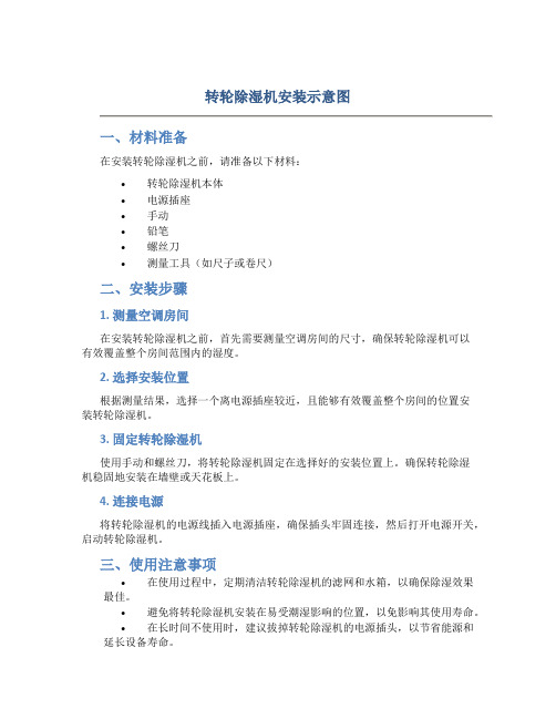
一、材料准备
在安装转轮除湿机之前,请准备以下材料:
•转轮除湿机本体
•电源插座
•手动
•铅笔
•螺丝刀
•测量工具(如尺子或卷尺)
二、安装步骤
1. 测量空调房间
在安装转轮除湿机之前,首先需要测量空调房间的尺寸,确保转轮除湿机可以
有效覆盖整个房间范围内的湿度。
2. 选择安装位置
根据测量结果,选择一个离电源插座较近,且能够有效覆盖整个房间的位置安
装转轮除湿机。
3. 固定转轮除湿机
使用手动和螺丝刀,将转轮除湿机固定在选择好的安装位置上。
确保转轮除湿
机稳固地安装在墙壁或天花板上。
4. 连接电源
将转轮除湿机的电源线插入电源插座,确保插头牢固连接,然后打开电源开关,启动转轮除湿机。
三、使用注意事项
•在使用过程中,定期清洁转轮除湿机的滤网和水箱,以确保除湿效果最佳。
•避免将转轮除湿机安装在易受潮湿影响的位置,以免影响其使用寿命。
•在长时间不使用时,建议拔掉转轮除湿机的电源插头,以节省能源和延长设备寿命。
以上就是关于转轮除湿机的安装示意图及使用注意事项,希望对您有所帮助。
祝您使用愉快!。
汉斯威除湿机面板操作使用说明

风速
低 中高
*
在设备正常运转状态下: 点击功能切换键,可选择除湿或者是通风功能
注:当切换到[除湿]模式时,设备会延迟3分钟启动,以保护压缩机
hsway
湿度设定
-- --
-- --
室内
22℃ 80%
▲
▲
通风…… 除湿……
定时关机… 定时启动…
风速
低 中高
*
设定步骤: 点击[ ]键,湿度显示开始闪烁,此时点击[▲] [▼]键, 调节数值至需求湿度(一般建议60%),设定好之后,静 置5秒无操作,设定湿度自动保存,然后恢复显示实际湿 度,设定完毕。
当湿度达到设定湿度时,设备自动停止;当超过设定湿 度时,自动启动。
注:正常显示的数字为当前区域的实际湿度; 闪烁时显示的数字为需求的设定湿度。
hsway
汉斯威除湿新风一体机
hsway/汉斯威, 让家更舒适!
THANK YOU
Hsway/汉斯威,一心只为呵护您的家。
-- --
-- --
室内
22℃ 80%
▲
▲
通风…… 除湿……
定时关机… 定时启动…
风速
低 中高
*
控制面板操作说明
hsway
开机与关机
-- --
-- --
室内
22℃ 80%
▲
▲
通风…… 除湿……
定时关机… 定时启动…
风速Biblioteka 低 中高*在关机状态下,长按[ 在开机状态下,长按[
]键3秒,设备启动 ]键3秒,设备关闭
hsway
调节风量档位
-- --
-- --
室内
22℃ 80%
▲
▲
除湿机电气安装培训教材xPPT

PART 02
除湿机电气系统组成与原 理
REPORTING
WENKU DESIGN
除湿机电气系统概述
电气系统作用
除湿机的电气系统是控制整个设备运行的核心,负责接收用户指令、驱动压缩机 、风扇等部件工作,同时监测设备状态,确保除湿机安全、高效运行。
主要组成部分
除湿机电气系统主要由控制面板、电源电路、驱动电路、保护电路等部分组成。
除湿机电气安装培训 教材
https://
REPORTING
目录
• 电气安装基础知识 • 除湿机电气系统组成与原理 • 电气安装步骤与操作规范 • 案例分析:除湿机电气安装实例解析 • 总结回顾与展望未来发展趋势
PART 01
电气安装基础知识
REPORTING
WENKU DESIGN
主要部件功能介绍
控制面板
接收用户操作指令,显示设备 运行状态,实现人机交互。
电源电路
为除湿机提供稳定的工作电压 ,确保设备正常运行。
驱动电路
驱动压缩机、风扇等负载工作 ,实现除湿功能。
保护电路
监测设备运行状态,当出现过载 、过热等异常情况时,自动切断
电源,保护设备免受损坏。
工作原理及流程分析
工作原理
常见故障类型及处理方法
电源故障
检查电源插头、电源线是否损坏或接 触不良,及时更换或修复。
压缩机故障
检查压缩机是否缺油、损坏或过载, 及时添加润滑油、更换损坏部件或调 整负载。
风扇故障
检查风扇叶片是否损坏、电机是否过 热或过载,及时更换损坏部件、清理 散热片或调整负载。
控制面板故障
检查控制面板是否受潮、损坏或接触 不良,及时烘干、更换损坏部件或调 整接触状态。
厂房加湿器施工流程

厂房加湿器施工流程空气湿度在不同的环境下都有不同的作用,室内湿度在30%左右,会让人感觉非常舒服,但是空气质量差的话,室内会出现干燥、异味等情况。
因此工厂等有对湿度要求较高的地方在设计时应该考虑到这一点。
室内空气太干会让人感到烦躁、不舒服。
一般加湿器设计是通过热交换把水加热,然后再进行加湿。
但其实有些大型厂有使用超临界水来加温加湿的,这样反而可能会产生危险的水蒸气。
因此应该选择有一定排风能力、可以直接利用空气中水蒸气来增加湿度等措施来解决问题。
而且超临界水经过高温蒸发后,很容易形成小颗粒细水珠,这样就能使水分不会堆积在一起。
再加上超临界水也具有冷凝效果和较好的蒸汽压力(在工业加湿器中用来提高机器的制冷效率),所以超临界水被广泛用于工业、商业以及医院等场所。
目前超临界水应用非常广泛,使用超临界水可以改善空气中水中含有的钙、镁离子(称为镁钙)以及各种杂质、霉菌和细菌等物质,对人体无害健康;而且采用空气中存在的矿物质进行蒸发使室内空气得到改善,不会对人体产生不良影响。
1.现场测量。
现场测量,需要知道室内环境的一些数据。
例如湿度、温度、噪音等。
湿度有两种方法:其一:用除湿机将湿度控制在10%以下是不需要加湿了。
所以选择除湿机是没有必要加湿了。
其二:用空气测量仪来测量室内的空气湿度。
测温元件一般选在室外或阳光直射的地方。
2.基础清理,根据厂房的尺寸和高度计算出水箱的长度、高度并绘制草图,将图纸交给施工方。
采用水浴房加湿器将室外的自然光引入室内。
该设备采用独特的不锈钢材质,完全不浪费自然光。
它的出风口为独特的设计,不仅可以使出风口与室内环境保持统一色调,还能保证室内的自然光线进入厂房。
并且采用先进的水浴模式,无需加水、不用电、不需任何人工辅助工具,整个生产过程安全可靠。
整个净化设备安装过程也是十分便捷快捷的一步。
净化设备的使用大大提高了生产效率和产品质量。
该设备充分利用了室外自然光对室内温度、湿度及无机盐进行调节的优势。
除湿机使用和操作规程

除湿机使用和操作规程目录1、重要安全说明3、设备使用注意事项4、设备说明5、设备安装6、设备开机检查事项7、设备操作规程8、产品日常维护9、常见故障分析及排除方法一、重要安全说明1.使用前,请先确认电源为220V/50HZ或380V/50HZ。
2.不要以拔出电源线的方式来停止除湿机运转。
3.在移动除湿机时应小心,不要滚压和损坏电线。
4.切勿将手指或棒状物伸入格栅内。
5.建议使用合适的电源开关,勿使用插头,必须安全接地。
6.不得操作于密闭狭窄空间。
7.请妥善保管此使用手册。
8.任何维修必须由专业人员进行。
二、设备使用注意事项1.使用环境:1.使用环境温度:5―38摄氏度2.避免使用在腐蚀性较强和易燃、易爆及大量灰尘的环境中;2.使用电源1.本机使用380V/50HZ电源,三相五线,机身背面有接地标志,使用前务必做好接地线连接。
本机安装必须由专业电工安装,若无专业电工,可电话联系生产工厂指导安装.3.机器开关1.机器控制面板上有开关键,严禁直接开关空开的方式进行开关机。
三、设备说明1.控制系统说明本机控制模式说明如下:3.1.1湿度显示:机器带有湿度显示功能,显示当前环境湿度状况。
3.1.2开关键: 机器使用薄膜式开关,第一次按键为开机,再次按键为关机。
3.1.3湿度设定:机器设有湿度设定功能,+为湿度设定增大,-为湿度设定减小。
3.1.4定时设定:设定时先按设定键,再按+\-设定所需时间即可.2.工作原理说明:除湿机工作系统分为二部分3.2.1制冷循环部分由压缩机、冷凝器、毛细管、套管式冷凝器及连接管道组成,低压制冷剂气体由压缩机吸入,压缩成高压气体,进入冷凝器并放出热量,经冷凝器冷却成液体,然后经过过滤器毛细管节流成为低压低温的气体混合物进入套管式冷凝器,由蒸发器蒸发为气体,吸收空气中的热量,再回到压缩机。
制冷剂工质在制冷系统内这样反复循环,达到制冷的目的。
3.2.2空气循环部分湿空气由离心风机吸入并通过空气过滤网进入蒸发器,当蒸发器的表面温度底于空气的露点温度时空气被冷却,空气中含有水分就会被凝聚下来,被冷却除湿后的空气继续前进,进入冷凝器并带走冷凝器释放出的热量,由离心风机送出,使空气中的相对湿度降低。
- 1、下载文档前请自行甄别文档内容的完整性,平台不提供额外的编辑、内容补充、找答案等附加服务。
- 2、"仅部分预览"的文档,不可在线预览部分如存在完整性等问题,可反馈申请退款(可完整预览的文档不适用该条件!)。
- 3、如文档侵犯您的权益,请联系客服反馈,我们会尽快为您处理(人工客服工作时间:9:00-18:30)。
精装修的房子因为前期没做除湿机,吊顶大面积霉变,拆掉重做,配置的是汉斯威新风除湿机FD50-P。
根据房梁结构及吊顶造型,合理设计风管走向及风口布置。
为了提高生活品质,安装了供氧净化系统,瞬间把邻居的小伙伴甩到月球去了。
汉斯威除湿新风系统FD50-P,接线侧盖打开,接线检修保养一步即可。
供氧净化系统外机。
因为房梁结构较多,有很多不可以打孔,吊顶也有很多造型,所以要合理避让,但同时也要尽量保持走向平直,保证循环风量充足。
转角处尽量控制角度平缓,减小风阻。
若空间允许,可用软管过梁,尽量避免使用过梁器,以减小风阻。
吊顶完成后,进行收尾工作。
风口安装。
吸氧终端。
汉斯威新风除湿一体机。