渐开线花键_中文参考版
花键齿轮参数中英文对照

渐开线花键 involute spline未注公差 undeclared tolerance未注倒角 undeclared chamfer调质 thermal refining端口 port chamfer模数 modulus齿形角 tooth profile angle变位系数 stand-off error齿圈径向跳动 geared ring radial runout 公法线长度及偏差 common normal跨齿数 spanned tooth count高频淬火 high-frequency quenching 配对齿轮 mating gear螺旋角 spiral angle压力角 pressure angle螺旋升角 lead angle图号 figure number齿厚 tooth thickness螺旋线 helix蜗杆 worm齿轮 gear齿轴 gear shaft转子轴 rotor shaft精度等级 precision class齿轮基本术语齿轮Toothed gear;Gear齿面Tooth flank长幅内摆线Prolate hypocycloid齿轮副Gear pair右侧齿面Right flank短幅内摆线Curtate hypocycloid平行轴齿轮副Gear pair with parallel axes左侧齿面Left flank渐开线Involute;Involute to a circle相交轴齿轮副Gear pair with intersecting axes 同侧齿面Corresponding flank延伸渐开线Prolate involute齿轮系Train of gears异侧齿面Opposite flank缩短渐开线Curtate involute行星齿轮系Planetary gear train工作齿面Working flank球面渐开线Spherical involute齿轮传动Gear drive;Gear transmission 非工作齿面Non-working flank渐开螺旋面Involute helicoid配对齿轮Mating gears相啮齿面Mating flank 阿基米德螺旋面Screw helicoid小齿轮Pinion共轭齿面Conjugate flank球面渐开螺旋面Spherical involute helicoid 大齿轮Wheel;Gear可用齿面Usable flank圆环面Toroid主动齿轮Driving gear有效齿面Active flank圆环面的母圈Generant of the toroit从动齿轮Driven gear上齿面Addendum flank圆环面的中性圈Middle circle of the toroid 行星齿轮Planet gear下齿面Dedendum flank圆环面的中间平面Middle-plane of the toroid 行星架Planet carrier齿根过渡曲面Fillet圆环面的内圈Inner circle of the toroid太阳轮Sun gear齿顶Crest;Top land啮合干涉Meshing interference内齿圈Ring gear;Annulus gear 槽底Bottom land切齿干涉Cutter interference外齿轮External gear齿廓Tooth profile齿廓修型Profile modification;Profile correction内齿轮Internal gear端面齿廓Transverse profile修缘Tip relief中心距Centre distance法向齿廓Normal profile修根Root relief轴交角Shaft angle轴向齿廓Axial profile齿向修形Axial modification;Longitudinal correction连心线Line of centres背锥齿廓Back cone tooth profile齿端修薄End relief减速齿轮副Speed reducing gear pair 齿线Tooth trace鼓形修整Crowning增速齿轮副Speed increasing gear pair 齿棱Tip;Tooth tip鼓形齿Crowned teeth齿数比Gear ratio 模数Module挖根Undercut传动比Transmission ratio端面模数Transverse module瞬时轴Instantaneous axis轴平面Axial plane法向模数Normal module瞬时接触点Point of contact基准平面Datum plane轴向模数Axial module瞬时接触线Line of contact节平面Pitch plane径节Diametral pitch端面啮合线Transverse path ofPineneedle 050328contact端平面Transverse plane齿数Number of teech啮合曲面Surface of action法平面Normal plane当量齿数Virtual number of teeth啮合平面Plane of action分度曲面Reference surface头数Number of starts;Number of threads 啮合区域Zone of action节曲面Pitch surface螺旋线Helix;Circular helix总作用弧Total arc of transmission齿顶曲面Tip surface圆锥螺旋线Conical spiral端面作用弧Transverse arc of transmission 齿根曲面Root surface螺旋角Helix angle;Spiral angle纵向作用弧Overlap arc基本齿廓Basic tooth profile导程Lead总作用角Total angle of transmission基本齿条Basic rack导程角Lead angle端面作用角Transverse angle of transmission 产形齿条Counterpart rack阿基米德螺旋线Archimedes spiral纵向作用角Overlap angle产形齿轮Generating gear of a gear外摆线Epicycloid总重合度Total contact ratio产形齿面Generating flank长幅外摆线Prolateepoicycloid端面重合度Transverse ratio基准线Datum line短幅外摆线Curtateepoicycloid纵向重合度Overlap ratio轮齿Gear teeth;Tooth摆线Cycloid标准齿轮Standard gears齿槽Tooth space长幅摆线Prolate cycloid非变位齿轮X-gero gear右旋齿Right-hand teeth短幅摆线Curtate cycloid标准中心距Referencrcentre distance左旋齿Left-hand teeth内摆线Hypocycloid名义中心距Nominal centre distance变位齿轮Gears with addendum modification;X-gears直齿轮Spur gear分度圆柱面Reference cylinder高度变位圆柱齿轮副X-gear pair with reference centre distance 斜齿轮Helical gear;Single-helical gear节圆柱面Pitch cylinder角度变位圆柱齿轮副X-gear pair with modified centre distance 直齿条Spur rack基圆柱面Basic cylinder高度变位锥齿轮副X-gear pair without shaft angle modification 斜齿条Helical rack齿顶圆柱面Tip cylinder角度变位圆柱齿轮副X-gear pair with shaft angle modification人字齿轮Double-helical gear齿根圆柱面Root cylinder变位系数Modification coefficient渐开线齿轮Involute cylindrical gear节点Pitch point变位量Addendum摆线齿轮Cycloidal gear节线Pitch linePineneedle 050328modification径向变位系数Addendum modification coefficient圆弧齿轮Circular-arc gear;W-N gear分度圆Reference circle中心距变位系数Centre distance modification coefficient双圆弧齿轮Double-circular-arc gear节圆Pitch circle圆柱齿轮Cylindrical gear假想曲面Imaginary surfance基圆Basic circle顶圆Tip circle 任意点法向压力角Normal pressure angle at a point定位面Locating face根圆Root circle任意点端面压力角Transverse pressure angle at a point 外锥距Outer cone distance齿距Pitch啮合角Working pressure angle内锥距Inner cone distance齿距角Angular pitch顶隙Bottom clearance中点锥距Mean cone distance公法线长度Base tangent length圆周侧隙Circumferential blacklash背锥距Back cone distance分度圆直径Reference diameter法向侧隙Normal blacklash安装距Locating distance节圆直径Pitch diameter径向侧隙Radial blacklash轮冠距Tip distance;crown to back基圆直径Base diameter锥齿轮Bevel gear冠顶距Apex to crown顶圆直径Tip diameter锥齿轮副Bevel gear pair偏置距Offset根圆直径Root diameter准双曲面齿轮副Hypoid gear pair齿线偏移量Offset of tooth trace齿根圆角半径Fillet radius准双曲面齿轮Hypoid gear分锥角Reference cone angle 齿高Tooth depth冠轮Crown gear节锥角Pitch cone angle工作高度Working depth端面齿轮Contrate gear顶锥角Tip angle齿顶高Addendum直齿锥齿轮Straight bevel gear根锥角Root angle齿根高Dedendum斜齿锥齿轮Skew bevel gear;Helical bevel gear背锥角Back cone angle弦齿高Chordal height曲面齿锥齿轮Curved tooth bevel gear 齿顶角Addendum angel固定弦齿高Constant chord height弧齿锥齿轮Spiral bevel gear齿根角Dedendum angle齿宽Facewidth摆线齿锥齿轮Enicycloid bevel gear任意点压力角Pressure angle at a point有效齿宽Effective facewidth零度齿锥齿轮Zerot bevel gear任意点螺旋角Spiral angle at a point端面齿厚Transverse tooth thickness圆柱齿轮端面齿轮副Contrate gear pair中点螺旋角Mean spiral angle法向齿厚Normal tooth thickness锥齿轮的当量圆柱齿轮Virtual cylindrical gear of bevel gear大端螺旋角Outer spiral angle端面基圆齿厚Transverse base thickness8字啮合锥齿轮Octoid gear小端螺旋角Inner spiral angle法向基圆齿厚Normal base thickness圆柱齿弧锥齿轮Spiral bevel gear with circle arc tooth profile 蜗杆WormPineneedle 050328端面弦齿厚Transverse chordal tooth thickness分度圆锥面Reference cone蜗轮Worm wheel固定弦齿厚Constant chord节圆锥面Pitch cone蜗杆副Worm gear pair端面齿顶厚Crest width齿顶圆锥面Face cone;tip cone圆柱蜗杆Cylindrical worm法向齿顶厚Normal crest width齿根圆锥面Root cone圆柱蜗杆副Cylindrical worm pair端面齿槽宽Transverse spacewidth背锥面Back cone环面蜗杆Enveloping worm法向齿槽宽Normal spacewidth前锥面Front cone环面蜗杆副Enveloping worm pair齿厚半角Tooth thickness half angle中锥面Middle cone阿基米德蜗杆Straight sided axial worm;ZA-worm槽宽半角Spacewidth half angle分锥顶点Reference cone apex渐开线蜗杆Involute helicoid worm;ZI-worm压力角Pressure angle轴线交点Crossing point of axes法向直廓蜗杆Straight sided normal worm;ZN-worm 齿形角Nominal pressure angle公共锥顶Common apex锥面包络圆柱蜗杆Milled helicoid worm;ZK-worm圆弧圆柱蜗杆Arc-contact worm;hollow flank worm;ZC-worm齿根圆环面Root tosoid椭圆齿轮Elliptical gear直廓环面蜗杆Enveloping worm with straight line grneratrix;TA worm 咽喉面Gorge非圆齿轮副Non-circular gear pair平面蜗杆Planar worm wheel;P-worm wheel喉平面Gorge plane圆柱针轮副Cylindsical lantern pinion and wheel平面包络环面蜗杆Planar double enveloping worm;TP-worm喉圆Gorge circle针轮Cylindsical tan tein gear ;pin-wheel平面二次包络蜗杆Planar double-enveloping worm wheel;TP-worm wheel分度圆蜗旋线Reference helix谐波齿轮副Harmoric gear drive锥面包络环面蜗杆Toroid enveloping worm wheel;TK-worm wheel螺纹Thread波发生器Wave generator渐开线包络环面蜗杆Toroid enveloping worm hich involute holicoidgeneratrix;TI-worm蜗杆齿宽Worm facewidth柔性齿轮Flexspine锥蜗杆Spiroid蜗轮齿宽Worm wheel facewidth 刚性齿轮Circular spline锥蜗轮Spiroid gear直径系数Diametral quotient非圆齿轮Non-circular gear Pineneedle 050328锥蜗杆副Spiroid gear pair咽喉半径Gorge radius分度圆环面Reference tosoid中平面Mid-plane齿宽角Width angle。
din5480渐开线花键标准

din5480渐开线花键标准DIN5480渐开线花键标准。
DIN5480渐开线花键是一种常见的机械连接元件,广泛应用于工程机械、汽车、航空航天等领域。
它具有传递大扭矩、高传动效率和稳定性好等特点,因此备受工程师和设计师的青睐。
本文将对DIN5480渐开线花键标准进行详细介绍,希望能为相关领域的从业人员提供一些参考和帮助。
首先,我们需要了解渐开线花键的基本结构。
渐开线花键是一种带有渐开线齿廓的轴向连接元件,其齿廓具有一定的曲线特性,能够在传递大扭矩的同时减小齿面载荷集中,提高传动效率和使用寿命。
在DIN5480标准中,花键的齿廓参数、尺寸公差、材料要求等都有详细规定,以确保其在不同工况下的可靠性和稳定性。
其次,我们需要了解DIN5480渐开线花键的标准规范。
DIN5480标准是德国标准化协会发布的一项机械传动元件标准,其中包括了渐开线花键的设计、制造、安装和使用等方面的规定。
在标准中,对于花键的齿廓参数、齿形公差、齿顶间隙、齿根间隙、齿槽等都有详细的规定,以确保花键在不同设备中的互换性和可靠性。
此外,DIN5480渐开线花键的应用也需要遵循一定的原则。
在实际工程中,我们需要根据具体的传动要求和工作环境来选择合适的花键型号和尺寸。
同时,在安装和使用过程中,需要严格按照标准规定的工艺要求进行操作,以确保花键的传动效率和安全可靠性。
总的来说,DIN5480渐开线花键标准是机械传动领域中非常重要的一部分,它为工程师和设计师提供了一种高效、可靠的机械连接方案。
通过本文的介绍,希望能够对相关领域的从业人员有所帮助,同时也希望大家能够在实际工程中充分发挥渐开线花键的优势,为工程机械和汽车等设备的性能提升和可靠运行做出贡献。
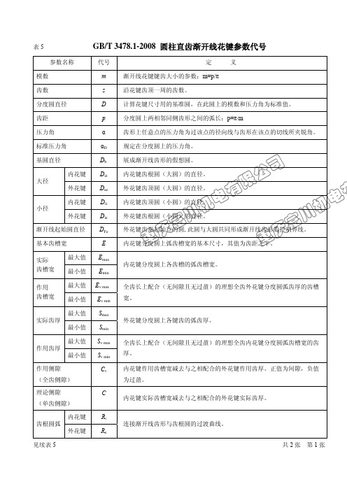
表5 渐开线花键参数代号
川机电 川机电 公法线长度
W
相隔 K 个齿的两外侧齿面与两平行平面相切,此两平行平面之间的垂直距
离。同一花键上实际测得的公法线长度的平均值。
重庆富 重庆富 注明:1、表中汉字为宋体,字号为 5 号;
2、字母代号为 Times New Roman 字体;
3、大小写字母字号均为 5 号再设置成下标格式。
共2张 第1张
续表 5 完
GB/T 3478.1-2008 圆柱直齿渐开线花键参数代号
参数名称
代号
定
义
齿形裕度
CF
总公差 加工公差
T
T&#花键连接中,渐开线齿形超过结合部分的径向距离。 实际齿槽宽或实际齿厚的允许变动量。 花键齿(或齿槽)的形状和位置误差的允许范围。 分度圆上任意两个同侧齿面间的实际弧长与理论弧长之差的最大绝对值的 允许范围。
全齿长上配合(无间隙且无过盈)的理想全齿外花键分度圆弧齿厚的齿槽 宽。
外花键分度圆上各键齿的弧齿厚。
全齿长上配合(无间隙且无过盈)的理想全齿内花键分度圆弧齿槽宽的齿 厚。 内花键作用齿槽宽减去与之相配合的外花键作用齿厚。正值为间隙,负值 为过盈。
内花键实际齿槽宽减去与之相配合的外花键实际齿厚。
连接渐开线齿形与齿根圆的过渡曲线。
质管办标准化管理员:郑家贵
2010 年 11 月 2 日
共2张 第2张
表5
GB/T 3478.1-2008 圆柱直齿渐开线花键参数代号
参数名称
代号
定
义
模数
m
齿数
z
分度圆直径
D
齿距
p
压力角
α
标准压力角
αD
基圆直径
Db
ANSI B92.1-1970(R1993) SAE美国渐开线花键-中文翻译完整版0429

翻译:朱晓峰节选至《美国机械工程师手册》第28版,有错之处,请指正。
SPLINES AND SERRATIONSA splined shaft is one having a series of parallel keys formed integrally with the shaft and mating with corresponding grooves cut in a hub or fitting; this arrangement is in contrast to a shaft having a series of keys or feathers fitted into slots cut into the shaft. The latter construction weakens the shaft to a considerable degree because of the slots cut into it and consequently, reduces its torque-transmitting capacity.花键轴是一种具有“一系列相互平行的齿、并且齿与轴整体成型”的轴,它与在轮毂上或者装配体上开的键槽相配合。
这种装置与“在轴上开槽并且与一组销子或者楔键相配合”的结构相反。
后者的结构由于在轴上开槽大大降低了轴(的强度),降低了传递扭矩的能力。
Splined shafts are most generally used in three types of applications: 1 ) for coupling shafts when relatively heavy torques are to be transmitted without slippage; 2) for transmitting power to slidably-mounted or permanently-fixed gears, pulleys, and other rotating members; and 3) for attaching parts that may require removal for indexing or change in angular position. 花键轴主要用在以下三种情况:1)需要在无滑动的联轴器上传递大的扭矩;2)用于向“可滑动的装配组件”或者“固定装配的齿轮组或滑轮副”传递动力,3)用于“要求指定滑移量或转角位置”的配件上。
DIN 5480-2 2006基于基准直径的渐开线花键 第2部分 公称尺寸和检验尺寸

5
模数 m = 0.6 mm ............................................................................................................................ 10
6
模数 m = 0.75 mm .......................................................................................................................... 12
2
引用标准 .......................................................................................................................................... 5
3
尺寸和测量的图表表示法 ................................................................................................................. 6
2006-05
DIN 5480-2
基于基准直径的渐开线花键 — 第 2 部分 公称尺寸和检验尺寸
Passverzahnungen mit Evolventenflanken und Bazugsdurchmesser — Teil 2: Nennmaβe und Prufmaβe
代替 DIN 5480-2:1991-10, DIN 5480-3:1991-10, DIN 5480-4:1991-10, DIN 5480-5:1991-10, DIN 5480-6:1991-10, DIN 5480-7:1991-10, DIN 5480-8:1991-10, DIN 5480-9:1991-10, DIN 5480-10:1991-10, DIN 5480-11:1991-10, DIN 5480-12:1991-10, DIN 5480-13:1991-10 和 DIN 5480 Bar. 1:1995-11
渐开线花键参数标注

渐开线内(外)花键参数标注参考资料在审查产品设计图纸的过程中,发现每位设计师对渐开线花键参数和检验方法的理解不同,在产品设计中采用的标注方法也有所不同,而且有一些不正确的地方。
为此,在现行的渐开线花键参数表的基础上,参考了渐开线花键标准应用手册,编写了《渐开线内(外)花键参数在产品图中标注参考资料》。
既能为设计师们在标注渐开线花键参数时提供方便,又能使在产品图纸中对渐开线花键参数的标注方法取得一致。
不过,“下马伊始”就乱讲,难免错误和不当,请提宝贵意见。
在产品图纸中标注渐开线花键参数的建议:1.由于渐开线内花键和外花键的有些参数在标注内容上有较大的区别,故建议在标注内花键或外花键时使用两种不同的表格。
2.渐开线内(外)花键参数表的边框也采用细实线,与尺寸界限和尺寸线使用相同的线型。
3.对于内花键:小径Dii的尺寸及其偏差标注在图形上;大径Dei(当大径定心时除外)、分度圆直径D和齿根圆弧最小曲率半径Rimin等的尺寸标注在内花键参数表中,其偏差不必标注,由工艺保证。
4.内花键小径Dii的极限偏差(非定心直径时)摘自GB/T 3478.1—1995内花键小径Dii的偏差单位:μm模数 m0.25~0.75 1.00~1.75 2.00~10.00直径Diimm H10 H11 H12>6~10 +58+90>10~18 +70+110+180>18~30 +84+130+210>30~50 +100+160+250>50~80 +120+190+300>80~120 +220+350>120~180 +250+4005.对于外花键:大径Dee 的尺寸及其偏差标注在图形上;小径Die (当小径定心时除外)、分度圆直径D 和齿根圆弧最小曲率半径Remin 等的尺寸标注在外花键参数表中,其偏差不必标注,由工艺保证。
6. 外花键大径Dee 的上偏差(非定心直径时)。
摘自GB/T 3478.1—19957. 外花键大径Dee 的公差(非定心直径时)。
渐开线花键的简化画法与标注(免费)
m(z-1.5) m(z-1.8) m(z-1.4) m(z-1.2) 配合类别为H/h时,CF=0.1m 0.2m 0.4m 0.3m 0.25m
例:已知m=3mm,z=25,αD=37.5°。绘制内外渐开线花键。 计算:分度圆直径D=mz=3×25=75(mm) 基圆直径Db=mzcos37.5°=3×25×0.7934=59.5(mm) 内花键大径Dei= m(z+1.4)=3×(25+1.4)=79.2(mm)
渐开线花键的联接画法
用剖视图表示花键联接时,其联接部分按外花键绘制。
花键联接时,外花键的小径等,应 用细实线画出,如图中红线所示。
后面的内容有点儿
深 !
三、渐开线花键的标注
花键的标注有两种:标记标注法和一般尺寸标注法。渐开线花键多 采用标记标注法。在有关图样和技术文件中,需要标记时,应符合下列 规定:
外花键:D=80mm,Db=69.28mm,Dee=84mm,Die= 74mm 内花键:Dei=86mm,Dii= 76mm
30°平齿根 (标记:30P)
m=4mm,z=20,αD=30°圆齿根渐开线内、外花键画法
外花键:D=80mm,Db=69.28mm,Dee=84mm,Die= 72.8mm 内花键:Dei=87.2mm,Dii= 76mm
db=84.6mm,齿顶圆直径da=96mm,齿根圆直径df =82.5mm。
国家标准没让你这样画齿轮! 那么,这样画的意义何在?
意义就是画画这种没什么用的立体图,玩玩! 上当了吧?怒火中烧了吧? TMD前面学了半天,你现在才告诉人家“玩玩”! 别……别急着骂,还是有一点小用场滴。 请往后看——
二、渐开线花键的规定画法及尺寸标注
内花键 外花键 花键副 齿数 模数 30°平齿根 30°圆齿根 37.5°圆齿根 45°圆齿根 45°直线齿形圆齿根 公差等级 标准编号 INT ENT INT/ENT z(前面加齿数值,如25z:表示齿数为25) m(前面加模数值,如3m:表示模数为3mm) 30P 30R 37.5 45 45ST
渐开线花键 中文参考版

渐开线花键外形尺寸 DIN5482非新设计本标准仅适用于互换性应用。
如需新的设计,请使用DIN5480标准。
考虑到现有刀具,本标准将一直有效,直到另行通知。
(参阅最后一段解释)尺寸单位:mm 压力角:30˚w w w.m公称尺寸 d 1 1)H12 d 2 H11 d 3 h11d 4d 5齿数模数m 变位lw=sw公称值r 1 max r 2 max kmin.参照轮廓3)15x12 15 12 14.511.5 12.88 +0.5 3.090 17x14 17 14 16.513.5 14.49 +0.7 3.321 18x15 18 15 17.514.5 16 10+0.4 2.975 20x17 20 17 19.516.5 19.212-0.2 2.282 22x19 22 19 21.518.5 20.8130 2.513 25x22 25 22 24.521.2 22.414 1.6+0.55 3.148 25x2228x25 28 25 27.524.5 26.2515+0.302 3.098 30x27 30 27 29.526.3 28 16+0.327 3.127 32x28 32 28 31.527.6 29.7517+0.102 2.867 35x31 35 31 34.530.5 31.518 1.75+0.676 3.35 35x3138x34 38 34 37.533.5 36.1190 2.985 40x36 40 36 39.535.5 38 20+0.049 3.042 42x38 42 38 41.537.5 39.921 1.9 +0.099 3.1 0.15 0.25 0.3 38x3445x41 45 41 44.540.6 44 22-0.181 2.933 48x44 48 44 47.543.2 46 23+0.119 3.28 50x45 50 45 49.544.6 48 24-0.181 2.933 52x47 52 47 51.546.5 50 25-0.231 2.875 55x50 55 50 54.549 52 26+0.019 3.164 58x53 58 53 57.552 54 27+0.518 3.741 60x55 60 55 59.554.5 56 28 2 +0.768 4.03 0.25 0.35 0.4 55x5062x57 62 57 61.556.5 60.9029-0.434 2.797 65x60 65 60 64.359.5 63 30+0.015 3.317 68x62 68 62 67.361.5 65.131-0.034 3.259 70x64 70 64 69.363.5 67.232-0.084 3.201 72x66 72 66 71.365.5 69.333-0.134 3.144 75x69 75 69 74.368.5 71.434+0.315 3.663 78x72 78 72 77.371.5 73.535+0.765 4.183 80x74 80 74 79.373.5 75.636 2.1+0.715 4.12568x6282x76 82 76 81.375.5 83.2537-2.4250.734 85x79 85 79 84.378.5 85.538-2.05 1.167 88x82 88 82 87.381.5 87.7539-1.673 1.6 90x84 90 84 89.383.5 90 40-1.799 1.456 92x86 92 86 91.385.5 92.2541-1.923 1.311 95x89 95 85 94.388.5 94.542-1.549 1.744 98x92 98 92 97.391.5 96.7543-1.175 2.177 100x94 100 94 99.393.5 99 44 2.25-1.299 2.0330.35 0.45 0.598x921)成型切削制造时公差允许到H14 2)基于轮廓中心线3)具参照轮廓参数的滚刀可用于制造对应模数的所有花键内花键齿槽宽测量非新设计w ww.b zf x w .c om本标准仅适用于互换性应用。
- 1、下载文档前请自行甄别文档内容的完整性,平台不提供额外的编辑、内容补充、找答案等附加服务。
- 2、"仅部分预览"的文档,不可在线预览部分如存在完整性等问题,可反馈申请退款(可完整预览的文档不适用该条件!)。
- 3、如文档侵犯您的权益,请联系客服反馈,我们会尽快为您处理(人工客服工作时间:9:00-18:30)。
75x69 75 69 74.3 68.5 71.4 34 +0.315 3.663
78x72 78 72 77.3 71.5 73.5 35 +0.765 4.183
80x74 80 74 79.3 73.5 75.6 36
28x25 3.098 30.764 30.72 30.794 30.750 30.838 30.794
30x27 3.127 32.718 32.673 32.748 32.703 32.792 32.748
32x28 2.867 33.954 33.915 33.975 33.936 34.014 33.975
95x89 1.744 86.778 86.696
98x92 2.177 89.841 89.762
100x94
3.5
-
2.033 91.875 91.796
5
外花键齿厚测量
1)平底量棒、量球。
2)测量值不考虑可能的齿系和同心度偏差。本表也使用于成品检验。热处理所引起的
变形应充分予以考虑,甚至从拉削制造时就可以考虑。
1.9
+0.099 3.1
0.15 0.25 0.3
38x34
45x41 45 41 44.5 40.6 44 22 -0.181 2.933
48x44 48 44 47.5 43.2 46 23 +0.119 3.28
50x45 50 45 49.5 44.6 48 24 -0.181 2.933
量球、量棒Mi–根据ISO公差带标准测量棒、球间距2)
H10
公称尺寸
d f
1)
公称齿槽宽
lw
2)
Max. Min.
15x12 3.090 9.186 9.084
17x14
3.0 2.5
3.321 11.016 10.930
18x15 2.975 12.145 12.058
20x17 2.5 2.0 2.282 15.618 15.529
92x86 92 86 91.3 85.5 92.25 41 -1.923 1.311
95x89 95 85 94.3 88.5 94.5 42 -1.549 1.744
98x92 98 92 97.3 91.5 96.75 43 -1.175 2.177
100x94 100 94 99.3 93.5 99 44
0.25 0.35 0.4 55x50
62x57 62 57 61.5 56.5 60.90 29 -0.434 2.797
65x60 65 60 64.3 59.5 63 30 +0.015 3.317
68x62 68 62 67.3 61.5 65.1 31 -0.034 3.259
70x64 70 64 69.3 63.5 67.2 32 -0.084 3.201
渐开线花键渐开线花键计算渐开线花键画法渐开线花键参数圆柱直齿渐开线花键日本渐开线花键标准渐开线花键标准渐开线花键的画法渐开线花键压力角proe渐开线花键
1
渐开线花键外形尺寸DIN5482
非新设计
本标准仅适用于互换性应用。如需新的设计,请使用DIN5480标准。考虑到现有刀
具,本标准将一直有效,直到另行通知。(参阅最后一段解释)
22x19 2.513 15.755 15.637
25x22
3.0 2.7
3.148 18.920 18.830
28x25 3.098 20.859 20.746
30x27
3.5 3.2
3.127 22.828 22.720
4
32x28 2.867 25.605 25.527
35x31
3.0 2.7
2.25
-1.299 2.033
0.35 0.45 0.5
98x92
1)成型切削制造时公差允许到H14
2)基于轮廓中心线
3)具参照轮廓参数的滚刀可用于制造对应模数的所有花键
内花键齿槽宽测量
非新设计
3
本标准仅适用于互换性应用。如需新的设计,请使用DIN5480标准。考虑到现有刀
具,本标准将一直有效,直到另行通知。(参阅最后一段解释)
3)对lw小于1.6mm的情况,公差带H10的计算与尺寸1.6~3mm的允许误差计算一
致。
4)测量值不考虑可能的齿系和同心度偏差。本表也使用于成品检验。齿系变化-包括
内花键在拉削时没有得到正确补偿-都将以合适的方式来调整,即切深,保证选择的配
合类型。
5)对sw小于1.6mm的情况,公差带e9,h9,k9的计算与尺寸1.6~3mm的允许误差计算
35x31
2.7
3.35 36.83 36.786 36.860 36.816 36.903 36.860
38x34 3.5 - 2.985 41.168 41.130 41.190 41.152 41.228 41.190
40x36 3.042 43.281 43.235 43.312 43.265 43.356 43.265
42x38 3.1 45.158 45.112 45.189 45.143 45.235 45.143
45x41 2.933 48.631 48.591 48.654 48.614 48.694 48.614
48x44 3.28 51.067 51.020 51.098 51.051 51.145 51.051
58x53
3.741 59.818 59.772 59.849 59.803 59.895 59.803
60x55 4.0 4.03 63.732 63.687 63.762 63.717 63.806 63.717
62x57 2.797 64.700 64.657 64.724 64.681 64.766 64.681
3.35 28.695 28.613
38x34 2.985 30.547 30.461
40x36 3.042 32.712 32.612
42x38
3.5 3.2
3.1 34.632 34.535
45x41 4.0 3.6 2.933 36.709 36.610
48x44 3.0 3.28 41.102 41.010
88x82 1.6
5)
90.142 90.096 90.167 90.122 90.213 90.122
90x84 1.4565)
92.198 92.151 92.224 92.177 92.270 92.177
52x47 52 47 51.5 46.5 50 25 -0.231 2.875
55x50 55 50 54.5 49 52 26 +0.019 3.164
58x53 58 53 57.5 52 54 27 +0.518 3.741
60x55 60 55 59.5 54.5 56 28
2
+0.768 4.03
一致。
解释
根据DIN5482标准用通用刀具加工内外花键时,请注意检查节圆直径。配合等级所需
的齿槽宽和齿厚,或所测数值必须根据DIN5480标准的规则考虑齿距和同心度偏差。
6
Md–根据ISO公差带标准测量跨棒、球距
4)
量棒(球)
e9 h9 k9
公称
尺寸
d f
1)
公称齿
厚sw4)
Max. Min. Max. Min. Max. Min.
尺寸单位:mm压力角:30˚
A–内花键B–外花键
齿槽宽lw的公差允许到:H10齿厚sw的公差参阅第6页
2
公称
尺寸
d1
1)
H12
d2
H11
d3
h11
d4 d5
齿
数
模数
m
变位
lw=sw
公称值
r1
max
r2
max
k
min.
参照轮
廓3)
15x12 15 12 14.5 11.5 12.8 8 +0.5 3.090
50x45 2.933 42.515 42.433
52x47
3.2
2.850 3.164 46.994 46.902
58x53
3.5
3.741 49.967 49.881
60x55
-
4.03 51.037 50.949
62x57 2.797 53.405 53.317
72x66 3.144 75.128 75.080 75.160 75.112 75.209 75.112
75x69 3.663 78.137 78.089 78.168 78.121 78.215 78.121
78x72 4.183 80.971 80.924 81.001 80.955 81.047 80.955
65x60
3.7
3.317 56.691 56.596
68x62 3.259 58.602 58.506
70x64 3.201 60.673 60.577
72x66 3.144 62.590 62.495
75x69 3.663 65.769 65.679
78x72 4.183 68.745 68.659
35x31 35 31 34.5 30.5 31.5 18
1.75
+0.676 3.35
35x31
38x34 38 34 37.5 33.5 36.1 19 0 2.985
40x36 40 36 39.5 35.5 38 20 +0.049 3.042