HAK-5-2B V2.0 双防区模块说明书
华北工控 emb-2500 用户手册说明书

EMB-2500 USER' Manual V2.0深圳华北工控股份有限公司:*************北京公司:************上海公司:021-********成都公司:************沈阳公司:************西安公司:************南京公司:************武汉公司:************天津公司:************新加坡公司:65-68530809荷兰公司:31-040-2668554更多产品信息请登陆:声明除列明随产品配置的配件外,本手册包含的内容并不代表本公司的承诺,本公司保留对此手册更改的权利,且不另行通知。
对于任何因安装、使用不当而导致的直接、间接、有意或无意的损坏及隐患概不负责。
订购产品前,请向经销商详细了解产品性能是否符合您的需求。
NORCO 是深圳华北工控股份有限公司的注册商标。
本手册所涉及到的其他商标,其所有权为相应的产品厂家所拥有。
本手册内容受版权保护,版权所有。
未经许可,不得以机械的、电子的或其它任何方式进行复制。
温馨提示1.产品使用前,务必仔细阅读产品说明书。
2.对未准备安装的板卡,应将其保存在防静电保护袋中。
3.在从包装袋中拿板卡前,应将手先置于接地金属物体上一会儿,以释放身体及手中的静电。
4.在拿板卡时,需佩戴静电保护手套,并且应该养成只触及其边缘部分的习惯。
5.主板与电源连接时,请确认电源电压。
6.为避免人体被电击或产品被损坏,在每次对主板、板卡进行拔插或重新配置时,须先关闭交流电源或将交流电源线从电源插座中拔掉。
7.在对板卡进行搬动前,先将交流电源线从电源插座中拔掉。
8.当您需连接或拔除任何设备前,须确定所有的电源线事先已被拔掉。
9.为避免频繁开关机对产品造成不必要的损伤,关机后,应至少等待30秒后再开机。
10.设备在使用过程中出现异常情况,请找专业人员处理。
11.此为A级产品,在生活环境中,该产品可能会造成无线电干扰。
G2-B系列说明书

G2-B系列模块使用说明书大连国彪应急电源集团有限公司第一章概述§1.1 前言当前我国消防系统使用的直流充电系统大部分采用传统的相控电源,但相控电源在效率、纹波、电磁辐射、热辐射、噪声等方面均不尽人意,监控系统不完善,采用1+1备份方式,对于越来越先进的仪器仪表、保护、控制、自动化设备很难满足其技术要求。
此外,现今大量采用免维护电池,由于相控电源的纹波系数大,浮充电压易波动,会出现蓄电池脉动充放电现象,对蓄电池损害极大,损害电池寿命。
高频开关电源由于其体积小,重量轻,技术指标优越,模块化设计,N+1热备份方式,便于“四遥”等优点,已在诸多领域得到广泛应用,如在计算机、航空航天、仪器仪表等方面。
我公司研制开发的G2B系列消防电源,是专为消防系统研发的新型“四遥”高频开关电源,模块采用世界领先的“谐振电压型双环控制的谐振开关电源技术”,具有体积小、重量轻、效率高、高可靠等优点。
输出标称电压为600V,配有标准RS-485接口,易于与自动化系统对接。
适于消防及相关行业使用。
§1.2 系统性能特点●模块化设计,N+1热备,可平滑扩容。
●全智能设计,通过串行通信,可自动实现:模块的开/关机、充电方式转换、输出电压调节、输出限流点整定、转换同步等功能。
●模块配有标准RS—485接口,方便接入自动化系统,实现“四遥”及无人值守。
●模块可带电插拔,更换安全方便。
§1.3、模块的主要特点1、效率高,模块效率可达到95%~96%。
2、重量轻,体积小。
3、采用“三相无源功率因数校正电路”,无中线,功率因数可达0.94。
4、采用隔离自主均流,并机不均流度<±3%。
5、模块内置直流输出隔离二极管,用户无需外设。
6、模块为LED数码管显示,分别设置显示切换按钮、手动调压按钮、拨码开关,操作简单。
§1.4、模块的主要功能一、保护功能●输出过压保护:输出电压过高对用电设备会造成灾难性事故,为杜绝此类情况发生,我公司的高频模块内有过压保护电路,出现过压后模块自动锁死,显示屏显示故障信息,故障模块自动退出工作而不影响整个系统正常运行;G2-B系列模块过压点为640±20V。
神盾H-5产品使用说明书

神盾H-5产品使用说明书(总7页)-CAL-FENGHAI.-(YICAI)-Company One1-CAL-本页仅作为文档封面,使用请直接删除神盾H-5产品使用说明书目录一、系统组成二、产品功能及技术参数三、设备安装四、软件使用及说明五、常见故障处理六、客户服务及技术服务承诺一、系统组成神盾H-5系统由以下几部分组成1、管理电脑2、巡更机(神盾H-5)3、巡更点4、人员卡(可选)5、智能巡检管理软件6、充电器7、锂电池8、皮套2、巡更点集成电路芯片密封在外壳内,防水防腐蚀,坚固耐用,可在各种恶劣环境中使用。
每个感应器编号不重码,无需供电。
识读卡次数:〉35万次寿命:一体式〉20年;卡片式〉10年环境温度:-40℃∽+85℃尺寸:直径8.5CM,,厚度:1CM重量:50g3、电脑通讯电缆采用USB数据通讯线,使用简单方便,下载数据速度快4、电池及充电器锂电池购买产品时所带的电池为不饱和状态,因此需要充满后再使用。
如果电池电压不够时,上电后液晶显示屏发现“请充电”指示,这时需要对电池进行充电,否则造成电池过量放电导致电池损坏。
充电器使用方法1)将待充电电池按正确方法放入充电器上2)充电时充电器指示灯为红色表示下在充电中,当充电器指示灯变为绿色时,表示电池已充电完成注意事项1)勿将充电器置于潮湿和高温环境下2)在使用过程中会有一定发热,在正常室温时,发热不超过60°C属于正常情况,是不会损坏锂电池3)新电池要充放三次才能达到最佳效果4)电池使用保障期为六个月5)电池抗抗震能力弱,请避免巡检器的强烈冲击6)危险场所请勿拆卸电池,严禁通讯,严禁充电5、产品使用功能说明USB接指示开机键《开机功能键》功能说明:1)开机键:当按下此键时,巡更机自动开启,进入读卡状态《指示灯》功能说明: 1)开机指示灯为红色,读卡成功后显示为绿色,读卡成功后并有振动提示《USB接口》功能说明: 1)USB与电脑通读接口二、设备安装1、巡更点安装1)首先确定巡更点安装位置,再拿冲击钻对准安装点冲(三个孔)嵌入胶塞。
贝福科技 两进两出0-5K欧姆电位计电子尺电阻信号隔离变送器 说明书

两进两出0-5K欧姆电位计电子尺电阻信号隔离变送器主要特性:>>输 入:输入电位器或电阻信号:0-50Ω/0-100Ω/0-200Ω/0-500Ω/0-1KΩ/0-2KΩ/0-5KΩ/0-10KΩ>>输出信号:输出标准电压信号:0-5V/0-10V/1-5V/0-±5V/0-±10V或输出标准电流信号:0-10mA/0-20mA/4-20mA>>辅助电源:5V、9V、12V、15V或24V直流单电源供电>>工业级温度范围: - 45 ~ + 85 ℃>>精度等级:0.1级>>隔离耐压:2500VDC(1mA,60S),输入1/输入2/输出1/输出2/电源五隔离>>安装方式:DIN35导轨安装>>外形尺寸:79x69.5x25mm典型应用:>>位移测量,角度测量>>电位计,电子尺信号的隔离变送图1 模块外观图>>电阻阻值的测量变送概述:贝福科技研发的电子尺信号变送器产品主要用于0-5K,0-10K等位移或角度传感器信号的隔离与变送(传感器需用户自己配),在工业上主要用于信号的隔离与变送。
该变送器输入采用恒压驱动,适用于3线传感器。
如果是2线传感器,也可以按要求定制成恒流驱动方式。
输入1、输入2、输出1、输出2和辅助电源之间完全隔离(五隔离),可以承受2500VDC的隔离耐压。
产品采用DIN35国际标准导轨安装方式,体积小、精度高,性能稳定、性价比高,可以广泛应用在石油、化工、电力、仪器仪表和工业控制等行业。
该系列电子尺信号隔离放大器使用非常方便,仅需接好线,即可实现位移信号的隔离变送。
产品选型:DIN22-IBF-R□-P□-□□注:默认是3线电位器输入,2线电阻输入订货时请备注说明。
选型举例1:输入1:0-5KΩ,输入2:0-5KΩ供电电压:24V 输出1:4-20mA,输出2:4-20mA 型号:DIN22-IBF-R7-P1-A4选型举例2:输入1:0-10KΩ,输入2:0-10KΩ供电电压:12V 输出1:0-5V,输出2:0-5V型号:DIN22-IBF-R8-P2-V1通用参数:精 度 ------- 0.1%输 入 ------- 电子尺、电位计、位移传感器、角度传感器、电位器、电阻等输出------- 标准的电压或电流信号。
FPC-5V2 Panel火灾防护控制器操作和用户手册说明书

Operation and User ManualFPC-5V2Panel Fire Protection ControllerIssue April 2019 Version 2INDEX1. Overview (2)2. Summary of Technical Characteristics (2)3. Technical Features (2)4. Assembly of unit (4)5. Installation guidelines (6)6. Specifications (7)7. Testing and Commissioning (7)8. FPC5-V2 Module Assembly (9)9. Adaptor plate/junction box coupling required (9)10. FPC5-V2 Module Connection to Condensed Aerosol Generators (10)11. Kiwa Declarations (11)This Operation & User Manual provides information on the FPC-5V2 fire protection module and how it is connected to the various FirePro Condensed Aerosol Generators.∙Autonomous fire suppression unit∙Primary power source: 3Vdc battery.∙Battery monitoring feature with LED - indication.∙Manual or Automatic battery status indication.∙Single input detection loop.∙Linear heat detector cable or a bimetallic sensorc onnectionsFigure 1: FPC-5V2 module.∙The FirePro fire protection module detects fire by using either a linear heat detector cable or a bimetallic sensor and activates the condensed aerosol fire suppression generators automatically in electrical cabinets and similar enclosures.Figure 2: Fire detection devices.∙Input detection terminal (J7 on the PCB) is available for connecting the linear heat detector cable or a bimetallic sensor. Output terminal (J6 on the PCB) can be used to connect the condensed aerosol fire suppression generator. Both J7 & J6 terminals are not electrically polarized.+-∙The fire protection module FPC-5V2 is powered by an internal 3V battery capable of providing the necessary amperage to activate a condensed aerosol fire suppression generator.∙The FPC-5V2 module is equipped with a battery monitoring feature. The battery status is indicated by the three LEDs located on the front of the unit.o The green LED flashes every four seconds, indicating that the battery is in good operating condition and is able to activate the aerosol generator whenrequired.o The yellow LED is illuminated when the battery voltage level has dropped but is still able to activate the aerosol generator when required.o The red LED is illuminated when the battery is unable to activate the aerosol generator and it is necessary to replace the battery immediately.o When no LED is illuminated, either the battery is installed in reverse polarity or it is fully discharged, or the unit is set in manual mode.Press Switch LED’s Status Press Switch+-Figure 4: Battery status indicator.∙The fire protection module FPC-5V2 can monitor the battery in both automatic and manual mode. Automatic mode means that the battery monitor function of the unit is operating continuously. Manual mode means that the battery monitor function of the unit does not operate continuously but only operates by pressing and holding the press switch located on the front of the unit above the LED. Automatic mode and Manual mode operation can be adjusted by changing the position of the "SW2" switch on the electronic PCB. When the switch is in the ON - position the unit is in Automatic mode. When the switch is in the OFF - position the unit is in Manual mode.Step 1: Remove the top safety the electronic PCB.Knob “A”Knob “B”FPC-5V2 Front SectionFPC-5V2 Main BodyFigure 5Step 2: Pass the Condensed Aerosol Generator wires through the FPC-5V2 main body. It is important to pass the Condensed Aerosol Generator wires from the same opening of the adaptor plate/junction box coupling.Figure 6Step 3: Install the FPC-5V2 main body to the Condensed Aerosol Generator by turningFigure 7Step 4:the electronic PCB.Bimetallic SensorLinear Heat Detector Cable+-Step 5: Install the CR2 battery on the battery holder "J4".Figure 9Step 6: Use a multimeter to make sure that there is no voltage at terminal "J6" on the electronic PCB. If there is a voltage reading, this means that the fire detection part of the unit has been activated, which will trigger the activation of the condensed aerosol generator when connected. Address this issue first and then proceed to the next step.Figure 10Step 7:Connect the Condensed Aerosol Generator wireselectronic PCB.Figure 11Step 8: To adjust the position of the "SW2" switch for Automatic or Manual monitoring mode operation, unscrew the electronic PCB from the front section of the FPC-5V2 module.Press SwitchFigure 12Step 9: Place the front section of the FPC-5V2 module into the main body of the FPC-5V2. Insert and tighten safety Knob "A" to assemble the unit.Figure 13The Linear Heat Detector cable that is connected to the FPC-5V2 module must be installed inside and on the ceiling of the electrical panel enclosure .Figure 14 Typical installationThe FPC-5V2 module equipped with a bimetallic sensor must be installed in such a way so that the bimetallic sensor is as close to the ceiling inside the electrical panel enclosure.FPC-5V2TerminalsDescriptionI/P terminal J7 Linear Heat Detector cable max 10m length I/P terminal J7 Linear Heat Detector cable max 10m lengthO/P terminal J6 Condensed Aerosol Generator 1 O/P terminal J6Condensed Aerosol Generator 1 Battery 3Vdc Lithium battery (CR2 (3V))I/P Rating IP30Enclosure Heat ResistanceWithstands for a short period heat of up to 180o CdegreesTable1: SpecificationsFor Testing, Commissioning and Simulation purposes, the Condensed Aerosol Generator is disconnected from the fire protection module FPC-5V2 and replaced by an indication circuit as per below diagram. The indication circuit includes a resistor and an LED (the indication circuit must be installed as illustrated below since the LEDs feature polarity).LED 1165Ω to 180Ω3.3VdcLED 165Ω to 180Ω18 ma0VdcBimetallic SensorLinear Heat Detector Cable+-+-165Ω to 180Ω++Step 1: Remove any power source connected to the system (CR2 Battery).Step 2: Connect the simulation LED circuit as described in figure 16.Step 3: Apply the power source to the system (CR2 Battery).Step 4:Create a short-circuit by using the two end-wires of the LHD cable (Linear Heat Detector cable) or apply heat to the bimetallic sensor.Step 5: Once the detection line is activated observe whether the LED illuminates.Step 6:Cancel the short-circuit on the detection line (LHD cable) or wait for the bimetallic sensor to cool down.Step 7: Observe whether the LED is off.Step 8:If no problem has been observed, remove the power source connected to the system (CR2 Battery).Step 9: By using an ohm-meter ensure that the ohmic resistance of the condensed aerosol generators is bStep 10: Replace the simulation LED circuit with the condensed aerosol generators.Figure 17: Measuring the Condensed Aerosol Generator resistance-Electrical Gland for LHD cable Knob “A”Knob “B”or Bimetallic SensorFront SectionMain BodyElectronic PCBCR2 BatteryFigure 18:Adaptor plate applicable to Condensed Aerosol Generator series: FP-20Adaptor plate applicable to Condensed Aerosol Generator series: FP-40, FP-80Junction box coupling applicable toCondensed Aerosol Generator series: FP-100, FP-200, FP-500, FP-1200, FP-2000, FP-3000, FP-4200, FP-5700,Table 1:Figure 19:For Box type Condensed Aerosol Generators FP-1200, 2000, 3000, 4200, 5700DeclarationsNumber K94463/05Replaces K94463/04Issued January 16th, 2017 first issueValid until December 4th, 2019Declaration of Conformity,based on the requirements § 4.4.2, § 4.4.3 and § 7.15 of CEN/TR 15276-1, regardingFireProIgnition device for Non-Pressurized Condensed Aerosol Generators•BTA ignition device (Bulb Thermal Activator)•FPC-5 ignition device in conjunction witho Bi-metal switcho Heat cableo Extension cable for bi-metal switch and heat cableKiwa Nederland B.V.Sir Winston Churchilllaan 273 Postbus 702288 AB RijswijkTel. +31 88 998 44 00 www.kiwa.nlExecuted by:CompanyFirePro Systems Ltd8 Faleas StreetAgios Athanasios IndustrialAreaCy-4041 Limassol - CyprusTelephone +357 25379999Email ****************This declaration consists of 6 pages.Publication of this declaration is allowed.Note:Publication of only this front page or parts of the declaration is considered as “not valid”. STATEMENT BY KIWAWith this declaration, Kiwa declares that legitimate confidence exists that the products supplied byFirePro Systems Ltd.comply with the technical specifications as laid down in this product declaration.Ronald KarelKiwaDeclarationThis product declaration is based on the functional requirement § 4.4.2, § 4.4.3 and test requirements § 7.15 of CEN/TR 15276-1. Ignition device(s) other than the standard electrical ignition device have not been tested as a part of the Non-Pressurized Condensed Aerosol Generators or separate component according § 7.Generator specificationsThe products mentioned below belong to this product declaration.Application and useTotal flooding fire-extinguishing systems are used primarily for protection against hazards that are in enclosures or equipment that, in itself, includes an enclosure to contain the extinguishant.Condensed aerosol generators can be used as a part of fire fighting systems in buildings, plants or other structures. It covers total flooding systems primarily related to buildings, plant and other specific applications, utilizing electrically non-conducting condensed aerosol fire extinguishants.The following are typical of such hazards, but the list is not exhaustive:a) Electrical and electronic hazards;b) Telecommunications facilities;c) Flammable and combustible liquids and gases;Where aerosol generators are used in a potentially explosive application, the suitability of the generator to the atmosphere for the determined life shall be assessed.The fire extinguishing components shall be suitable for extinguishing fires of the following classes:•Class A according EN2•Class B according EN2Conditions for application•The numbers and types of the extinguishing components have to be determined in conformity with the guidelines and calculation methods of the supplier.•Distribution is to be done by supplier or companies authorised by the supplier.•Before usage an instruction is to be given by a trainer or instructor for this product authorized by the supplier.•The installation and maintenance of the fire extinguishing components have to take place according to the specifications of the supplier/manufacturer, CEN/TR 15276-2 and/or evaluation guideline BRL-K23003.Point of interest during use or limitation of useThe condensed aerosol extinguishing components should not be used on fires involving the following unless relevant testing by accredited testing laboratories has been carried out to the satisfaction of the Authority:•Temperatures for use of aerosol extinguishing agents shall be within the supplier’s listed limits.•Local applications 1) of condensed aerosol extinguishing systems are not covered by this product declaration.o Local applications require a pre-engineered and pre-designed system which has been tested and approved for a specific application by an authority such as Kiwa or by an accredited testing laboratory.1) a local application is used for the extinguishment of surface fires in flammable liquids, gasses, and shallow solids, where the enclosure does not conform to the requirements for total flooding.The above list may not be exhaustive.ManualAt delivery the product should be accompanied by an operation manual in the English language, known and authorized by Kiwa. Following minimum items shall be described:•Type of aerosol generators;•Design application density;•Description of occupancies and hazards to be protected against;•Specification of aerosol generators;•Equipment schedule or list of materials for each piece of equipment or device, showing device name; supplier, model or part number and description;•System calculation;•Enclosure pressurization and venting calculations;•Description of fire detection, actuation and control systems.•Requirements for inspection, maintenance and testing of an aerosol fire-extinguishing system and for the training of inspection and maintenance personnel.For specific details regarding the owner’s manual, see CEN/TR 15276-1.MarkingThe products should be marked with the Kiwa®-mark.Recommendations for CustomersCheck at the time of delivery whether:•The supplier has delivered in accordance with the agreement;•The mark and the marking method are correct;•The products show no visible defects as a result of transport etc.If you should reject a product on the basis of the above, please contact:•FirePro Systems Ltdand, if necessary,•Kiwa Nederland B.V.Consult the suppliers processing guidelines for the proper storage and transport methods.Cross reference CEN/TR 15276-1, Fixed fire fighting systems - Condensed aerosol extinguishing systems - Part 1: Requirements and test methods for components, February 20091) A = Applicable N/A = Not Applicable Not testedDISCLAIMERFirePro Systems makes no representations or warranties of any kind, either express or implied, statutory or otherwise, including but not limited to warranties of merchantability, fitness for a particular purpose, of title, or of non-infringement of third party rights, including the intellectual property rights of others.Any information provided by FirePro Systems, relevant to the system engineering of the project is indicative and for guidance purposes only.ompatible with the equipment used in the system. Furthermore, the responsibility for the preparation and/ or approval of a project, subject to its specifications/ technical features and its related documentation, designs or drawings adherence (e.g. design documentation, construction, as-built drawings, circuit diagram, cable lengths and voltage drop calculations, etc.) to local, national and international laws and regulations, falls entirely within the scope of the contractor/ consultant assigned for the installation and commissioning.L IMITATION OF LIABILITYIn no event, regardless of cause, shall FirePro Systems be liable for any indirect, special, incidental, punitive or consequential damages of any kind, whether arising under breach of contract, tort (including negligence), strict liability or otherwise, even if advised of the possibility of such damages.NOTEFirePro is constantly updating its products and systems to the state of the art and therefore reserves the right to make changes in design, equipment and technology. You cannot therefore base any claims on the data, illustrations or descriptions contained in this literature.。
UTB5DPM 双对交流保护模块商品说明书
CATALOG NUMBERUTB5DPMCERTIFICATIONSFEATURES多级保护和良好过电压保护功能有助于确保最低剩余浪涌电压到达敏感设备共模和差模保护功能可防止两种可能的浪涌情况Surge rating to 20 kA 8/20 μs is ideal for exposed wiring产品属性Article Number: 702893Nominal System Voltage (Un): 0 - 3 VAC; 0 - 5 VDCMax Continuous Operating Voltage (Uc): 5 VAC; 7 VDCRated Load Current (IL): 800 mAFrequency: 0.5 MHzLoop Resistance: 0.6 ΩMax Discharge Current (Imax), L+L-PE: 20 kA 8/20 -sProtection Modes: Common; DifferentialTechnology: Gas Discharge Tube (GDT); Metal Oxide Varistor (MOV); Silicon Avalanche Diode (SAD) Voltage Protection Level (Up), L-L: 10 V @ 3 kA VTemperature: 从 -20 到 65 °CEnclosure Material: UL® 94V-0 热塑性塑料Depth (D): 43 mmHeight (H): 65 mm Width (W): 12 mmUnit Weight: 0.02 kg Complies With: ANSI®/IEEE® C62.41.2-2002 Cat A, Cat B, Cat CDIAGRAMS警告应仅根据 nVent 的产品说明书与培训材料安装并使用 nVent 的产品。
BP2b技术说明书

以Tlk表示差动动作于母联逻辑;
以F1,F2分别表示I母、II母故障,0表示无故障,1表示故障。
则出口逻辑计算公式为:
T1=F1* S11+F2* S21
T2=F1* S12+F2* S22
……
Tn=F1* S1n+F2* S2n
2.11
工作条件:振动响应、冲击响应严酷等级为I级
运输条件:振动耐久、冲击耐久及碰撞检验严酷等级为I级
3
3.1
各种类型的母线保护就其对母线接线方式、电网运行方式、故障类型以及故障点过渡电阻等方面的适应性来说,仍以按电流差动原理构成的母线保护为最佳。带制动特性的差动继电器(亦即比率差动继电器),采用一次的穿越电流作为制动电流,以克服区外故障时由于电流互感器(以下称TA)误差而产生的差动不平衡电流,在高压电网中得到了较为广泛的应用。BP系列母差保护以此为基础,结合微机数字处理的特点,发展出以分相瞬时值复式比率差动元件为主的一整套电流差动保护方案。下述各元件判据除非特别说明,都是分相计算,分相判别。
2.9
实验项目
耐受值
参照标准
介质强度
实验
2kV(有效值)交流,1分钟
GB14598.11,Ⅲ级
IEC255-22-1
冲击电压
实验
5kV, 1.2/50μs,0.5J
标准雷电波
K5B操作说明
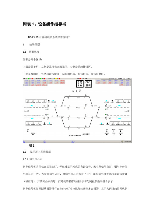
附表1:设备操作指导书DS6-K5B计算机联锁系统操作说明书1 站场图型1.1 界面风格屏幕分两个区域:上部是菜单栏:左侧是系统状态表示区,右侧是系统按钮区。
下部是视图区:包括功能按钮区、站场图形区、指示灯区、提示报警区。
图11.2 显示屏上图形显示1.2.1 信号机显示列车信号机关闭状态显示红灯,开放时显示相应的允许信号。
若室外信号点灯,则与室外信号机显示一致,若室外信号灭灯,则信号机显示带有“×”。
调车信号机关闭状态显示蓝灯(或红灯),开放时显示白灯。
信号机的名称用拼音字母与阿拉伯数字组合表示。
列车信号机灯丝断丝报警只有在室外点灯时出现灯丝断丝才会报警,显示为闪烁的信号机状态,同时屏幕下方的报警信息栏会有相应文字报警。
排列进路时,点击列车按钮后,显示绿色闪烁文字同时信号机名称后加“LA”或“A”字符,点击调车按钮后,显示白色文字闪烁同时信号机名称后加“DA”或“A”字符。
进路锁闭后按钮名称恢复原状。
如遇屏幕有按钮闪烁需取消时,按压相应咽喉的“总取消”按钮。
1.2.2 轨道区段显示轨道区段空闲状态显示为兰色光带,区段锁闭显示白色光带,区段占用显示红色光带。
无岔区段和股道名称固定显示在对应轨道区段附近。
注意:锁闭的区段占用后出清,若该区段未正常解锁,显示绿光带(绿光带与白光带联锁逻辑一致,都代表区段锁闭)。
1.2.3 道岔表示道岔通过所在轨道区段断开和连接的状态表示当前开通位置。
道岔名称用道岔号的数字表示。
道岔在定位时,道岔名显示绿色;道岔在反位时,道岔名显示黄色;道岔四开时,道岔名显示红色。
道岔发生挤岔故障时,道岔名显示红色并闪烁。
道岔单锁、总锁闭、防护或上电锁闭时,在道岔岔尖处显示一个圆圈。
颜色同当前道岔名称颜色,道岔解锁后圆圈消失。
注意:当被防护的道岔所属道岔区段为该进路的进路内区段时,被防护的道岔不画圆圈,但其仍为该进路的防护道岔。
道岔封闭时,道岔名称上显示一个方框,颜色同当前道岔名称颜色,道岔解封后,方框消失。
- 1、下载文档前请自行甄别文档内容的完整性,平台不提供额外的编辑、内容补充、找答案等附加服务。
- 2、"仅部分预览"的文档,不可在线预览部分如存在完整性等问题,可反馈申请退款(可完整预览的文档不适用该条件!)。
- 3、如文档侵犯您的权益,请联系客服反馈,我们会尽快为您处理(人工客服工作时间:9:00-18:30)。
HAK-5-2B V2.0双防区总线地址模块使用说明书
HAK-5-2B V2.0 2防区报警模块是具有总线通讯功能的防区扩展设备,其对于与远距离的探测设备的连接、或在周界防范等场合中非常实用,可与HAK-5-6002,HAK-5-64B,HAK-5-16C等系统配套使用;带有地址编码设置开关。
1. 性能特点:
●可接入2个有线探测设备
●总线通讯方式
●探测设备为常闭输入
3.与报警主机连接使用说明
●接线说明:如果和报警主机共用电源,将“红、绿、黄、黑” 4芯线分别与主机的“红、绿、黄、黑” 4端子相连;如果和报警主机不共用电源,将“绿、黄、黑” 3芯线分别与主机的“绿、黄、黑” 3端子相连,将“红、黑” 2芯线与自己的电源正、负极相连。
●在同一台报警主机上使用时,每一个报警模块有自己的唯一地址,不能与其它报警模块的地址相同。
地址范围及设定,请参考报警主机的安装或使用手册。
4.指示灯说明
●电源状态指示灯说明:输入电源的电压大于最低工作电压时, 电源状态指示灯常亮;一旦发现输入电
源的电压低于正常工作电压时,电源状态指示灯最少快速闪烁5秒,如果一直没有恢复,电源状态指示灯会一直闪烁。
●通信状态指示灯说明:
1.常亮:模块接收到正常通信;
2.快速闪烁(1秒钟闪烁4次):模块1秒钟内没有接收到任何通信数据;
3.慢速闪烁(1秒钟闪烁1次):模块接收到数据,但5秒钟内没有接收到任何正确的数据。
5. 地址编码开关
在将HAK-5-2B V2.0接入系统使用时,必须对其进行地址编码,编码通
过编码开关进行设置,地址编码采用2进制编码方式。
编码开关按“12345678”顺序排列设置二进制地址。
例如:某防区扩展模块的编码为13;对应的位二进制数为:00001101,
在地址拨码开关对应的顺序为1-8(即高位为1,低位为8)
1,2,3,4,7位不动, 5,6,8位拨到”ON”一边
附:地址编码表
注意:请按照本安装指南进行安装;在连接HAK-5-2B V2.0之前请先断开系统电源。