数字无线话筒使用说明书(K歌)
无线话筒使用方法

无线话筒使用方法
1.安放话筒:将无线话筒的接收器放置在一个固定位置,避免移动干扰信号接收。
2.开启无线话筒:打开话筒电源开关,等待话筒与接收器建立稳定的无线连接。
3.选择信道:打开接收器上的信号选择按钮,调整到无线话筒使用的频道。
4.测试话筒:在使用话筒之前,建议测试音响效果,可以通过接收器上的音量调节按钮测试话筒的音质和音量。
5.使用话筒:穿上话筒,触摸到麦克风部分,适当调节音量和靠近或远离嘴巴的距离,确保说话清晰,音量正常。
6.存储和保养:使用完话筒后,关掉话筒电源开关,将话筒放回到存储盒中,并定时清理麦克风部分,保持干净。
数字无线话筒使用说明书(K歌)
数字无线话筒使用说明书一、手持开关机1.将两节5号电池装入手持并拧紧网头(注意电池负极朝下,电池装反将损坏手持),向上推开关打开手持,此时电源指示灯亮,手持进入开机状态。
如果电源指示灯闪烁表示电池已耗尽,请更换电池再开机。
2.向下推开关电源指示灯熄灭,手持关机。
长时间不使用话筒请将电池取出。
二、接收机连接与开关机(专业)1.将音频连接线一头插接收机音频输出2另一头插到用户的音频设备(如功放、前级等)。
将12V开关电源插入220V交流插座,输出直流12V插入接收机DCIN,蓝色电源指示灯亮,接收机进入开机状态。
2.按住电源键一秒可以开启和关闭接收机电源。
3.断电后重新通电主机将自动进入开机状态,此时无需再按电源键开机。
三、接收机与电脑的连接与开关机(个人)1.将USB连接线两头分别插入电脑和接收机的USB接口。
蓝色电源指示灯,接收机进入开机状态。
电脑自动把音频输入输出设备切换成接收机。
(首次使用接收机的时候,电脑会自动安装驱动,电脑会依次出现图3所示的画面,直到硬件安装成功)2.将音频连接线一头插接收机音频输出1另一头插到用户的桌面音响输入端。
3.此时接收机将自动成为酷我k歌或QQ等者其他应用软件的音频输入输出设备。
(如果不能使用请参见疑难解答)4.按住电源键一秒可以开启和关闭接收机电源。
5.断电后重新通电主机将自动进入开机状态,此时无需再按电源键开机。
四、对码1.接收机开机后按功能键进入A通道对码状态,电源指示灯和A通道的射频指示灯亮,此时A通道可以对码,再按功能键进入B通道对码状态,电源指示灯和B通道射频指示灯亮,此时B通道可以对码。
再按功能键又将切换到A 通道,如此循环。
2.按照上一步将接收机切换到需要对码的通道,再按电源键,该通道射频指示灯闪烁,此时打开任意一支手持,接收机将自动与手持实现连接,连接成功后该通道射频指示灯和音频指示灯同时亮起一秒。
说明这个通道的手持对码成功,即可使用。
3.重复步骤1和步骤2以实现另一个手持与对应通道的对码。
杰尼奥电子D5000系列数字无线麦克风系统说明书

D5000 Series Digital Wireless Microphone SystemCOOKBOOKHeadset microphone WH-4000H WH-4000ATie-clip microphone YP-M5300YP-M5310Wireless antenna YW-4500Antenna distributor WD-5800Digital wireless transmitter WM-D5300 (belt-pack type)Digital wireless microphone WM-D5200 (handheld type)Battery charger BC-2000Rechargeable battery WB-2000-2SpeakerAmplifierDigital wireless receiverWT -D5800IndexSystem Equipment ConfigurationSystem Equipment Configuration How the Digital Wireless System Works Advantages of the Digital Wireless System Installation/Setting Procedures – One Room Installation/Setting Procedures – Multiple Rooms Installation of the YW-4500 Wireless Antenna Antenna Distribution Frequency T ableProcedure for Reusing the Same Frequency Encryption Function Settings Interference Countermeasures Antenna Attenuator FBS Setting EQ SettingOptimizing Sound Volume...1...2...3, 4...5...6...7...8, 9...10, 11, 12, 13...14, 15...16...17...18...19...20 (21)*BC-2000 and WB-2000-2 are not designed for the use in the U.S. and Canada, and available in these countries.**How the Digital Wireless System WorksSignal waveforms are used to represent sound, and the state of the sound is expressed according to the width or height of the waveform. Wireless microphones transduce the waveform of audio entering the microphone into an electrical signal and transmit that signal to a tuner over radio waves. In this event, it is an analog wireless system that processes the audio signal as it is in the waveform. On the other hand, it is a digital wireless system that digitally processes the audio signal.More specifically, in the digital system, after an analog signal (waveform) is transduced into a digital signal (asignal simplified by binary numbers 0 and 1) and transmitted by radio, the digital signal is demodulated into an analog signal and then the audio is output. By digitally processing and simplifying the audioinformation to be transmitted, the system can have a variety of advantages, including strong immunity to noise and maintenance of clear sound.Let’s have a look at the “D/U ratio” of analog-to-digital wireless systems. The D/U ratio refers to the ratio of the desired (D) signal to the undesired (U) signal (unit: dB). The desired signal represents the level of that signal, while the undesired signal represents the level of signal interference, otherwise called noise. The D/U ratio decreases as the undesired signal increases. The D/U ratio can be considered to be a value necessary to maintaining clear sound in a wireless system. If a comparison is made of the necessary D/U ratio between analog and digital wireless systems, it is 40dB for analog systems and 20dB for digital systems. From this, it can be seen that the digital wireless system has an edge over the analog wireless system by 20dB in terms of necessary D/U ratio, indicating that the digital system can maintain clear sound in circumstances where a lot of undesired signals are present.» How the Digital Wireless System Works» Why are digital wireless systems resistant to interference signals?Analog System Digital SystemDigital signal processing of analog audioDemodulation of digital to audible analog signal(analog)“H el l o ”Audio (analog)12Wireless receiverBroadcast122Not only can the digital wireless system reduce the influence of noise, it can also maintain clear sound quality by means of digital processing. In addition to this, there are various advantages unique to the digital wireless system.» Use of Multiple Channels in the Same AreaSince the wireless microphone makes itself a source of noise, when using multiple channels in the same area, channels must be arranged to avoid radio interference due to intermodulation interference. In the case of the analog wireless system, the most efficient channel arrangement is as shown in the [Analog] figure below if the intermodulation interference of radio waves is taken into consideration. In this arrangement, the simultaneous use of 6 channels is all it can handle per 4 MHz band.* This is an example.In the digital wireless system, however, since one of its features is being immune to the influence of noise, even when the intermodulation interference occurs, individual channels are less likely to be affected by it. As a result, equal-interval channel arrangements such as shown in the [Digital] figure below becomes possible, allowing up to 10 channels to be used simultaneously per 4 MHz band.* This is an example.» Interference Noise MutingAnalog systems are prone to generation of strange noises when exposed to radio interference. Conversely, radio interference is muted in digital systems, so strange noises are not produced.» Reuse of the Same ChannelAnother advantage of the digital wireless system is that simultaneous use of multiple microphones on the same frequency in the same area can be realized more easily because of its immunity to radio interference and noise.In the case of analog systems, the distance between microphones should be at least 100 meters when using the same frequency channel in the same area to ensure 40 dB of D/U ratio. However, in the case of digital systems, the distance can be reduced to 30 - 40 m*, making it easier to cope with even a building (area) with multiple rooms that require multiple microphones.*This can change depending on antenna mounting conditions or room conditions, such as the thickness or material of walls.Area and RoomRoomRoom» Improved SecurityConventional analog wireless systems transmit their audio signals through FM modulation. With this method, it is possible that communications could be intercepted by general broadband receivers (FM radio, etc.), causing much anxiety in terms of security. On the other hand, with digital systems, since the audio is transmitted through digital modulation, only noise can be heard if received by a broadband receiver. This can prevent exposure of information, leading to improvements in the security of information communication.(Horizontal coverage of antennas, Page 7)the supplied antenna.the supplied antenna.(Installation of the YW-4500 Wireless antenna, Page 7)o Step (3)(Antenna distribution, Page 8, 9)1) Select an arbitrary bank from Banks 1 – 4 at the receiver. (Frequency table, Page 10 -13) If you need more simultaneously usable channels, then use Bank A – F . In this case, please switch transmitter's T ransmission Output to "L (1mW)".* Banks A – F cannot be used when including existing analog wireless equipment in the system. 2) Check for idle channels using the channel scanning function.3) Similarly, perform bank settings and idle channel assignments for the remaining receivers.4) Set the transmitters for the same bank and frequency channels as the receivers.Perform encryption settings if it is necessary to prevent eavesdropping.(Encryption settings, Page 16)(Radio interference countermeasures, Page 17)(FBS settings, Page 19)(EQ Settings, Page 20)(7) Optimize the sound volume.(Sensitivity and volume settings, Page 21)Installation/Setting Procedures - One Room(1) Determine the operation range. (Horizontal coverage of antennas, Page 7)the supplied antenna. Use the supplied antenna.the supplied antenna. Use the YW-4500 external antenna.(Installation of the YW-4500 Wireless antenna, Page 7) (2) Determine the number of transmitters to use.o Step (3)(Antenna distribution, Page 8, 9)(3) Confirm the number of channels that can be simultaneouslyused by the frequency table. (Frequency table, Page 10 - 13)Page 14,15)1) Select an arbitrary bank from Banks 1 – 4 at the receiver. (Frequency table, Page 10 - 13)If you need more simultaneously usable channels, then use Bank A – F.In this case, please switch transmitter's T ransmission Output to "L (1mW)".* Banks A – F cannot be used when including existing analog wireless equipment in the system.2) Check for idle channels using the channel scanning function.3) Similarly, perform bank settings and idle channel assignments for the remaining receivers.4) Set the transmitters for the same bank and frequency channels as the receivers.Perform encryption settings if it is necessary to prevent eavesdropping. (Encryption settings, Page 16)(Radio interference countermeasures, Page 17)(8) Optimi sound quality.(FBS settings, Page 19)(EQ Settings, Page 20)(Sensitivity and volume settings, Page 21) Installation/Setting Procedures - Multiple RoomsPoint 1Mount the two antennas within 20 – 30m (outdoor applications: 40 – 50m) visible range from the microphone’s area of intended use.Both antennas should be within visible range from any location where the microphones are to be used. This is necessary for ensuring optimal conditions for one antenna to receive signals when the microphone my experience the other antenna's dead spot. In other words, the shape of the room does not matter provided that the above conditions are met. On a diagram of the site, use a compass to draw two circles representing a radius of 20 – 30m with each antenna as the central point. If usage locations fall within either of the two circles, such locations can be deemed to be okay.Point 2As a guideline, the distance between the two antennas should be 3 – 18m. Although the coverage area becomes wider as the distance between antennas increases, this degrades the diversity effect, and signal interruption will become more liable to occur.If possible, locate one antenna in the direction that can be viewed from the position where the microphone is held, and the other antenna in the opposite direction (behind the microphone holder).Point 3In indoor installations, as a general guideline, install antennas at a height of 2 – 4m above the floor, lest the signal be blocked by people in the room. Keep the antennas about 30cm below the ceiling. Install the antennas so they face in the specified directions. When making protectors, use resin or timber and do not use metallic materials.• Avoid positioning antennas close to metallic objects wherever possible.• Avoid mounting antennas inside a ceiling or wall.• Select locations where the antenna can be protected from being hit and damaged by objects.• Protect the antennas against rain water.Important points for selecting the mounting position of diversity antennas are as follows:Horizontal coverage of antennas under optimal conditionsInstallation of the YW-4500 Wireless Antenna• YW-4500• WT -D5800 Rod Antenna• Using 1 - 3 channelsAntennas can be distributed without using the WD-5800 Antenna Distributor.• Simultaneous use of 4 channels• Simultaneous use of 5 – 8 channelsaudio• Simultaneous use of 9 -16 channels• Simultaneous use of 17 - 32 channelsaudioto mixeraudioto mixeraudioto mixeraudioto mixeraudioto mixeraudioto mixeraudioto mixeraudioto mixeraudioto mixeraudioto mixeraudioto mixeraudioto mixerSplit antennas into two systems and construct a system of up to 32 channels.• Frequency table which can be used with 5000 Series analog wireless systemCompatible Frequency List*WM-D5200/D5300, WT-D5800: BANK 1 - 4WM-4200/4300/5220/5270/5320/5225/5265/5325: BANK 1– 4WT-4800/5800/5805: BANK 1– 4WM-4210/4220/4310, WT-4810/5100/5810, WTU-4800: BANK 1• When needing more channels*Banks A - F cannot be used when including existing analog wireless equipment in the system.Compatible Frequency List*WM-D5200/D5300, WT-D5800• Frequency table which can be used with 5000 Series analog wireless systemCompatible Frequency List*WM-D5200/D5300, WT-D5800: BANK 1 - 4WM-4200/4300/5220/5270/5320/5225/5265/5325: BANK 1– 4WT-4800/5800/5805: BANK 1– 4WM-4210/4220/4310, WT-4810/5100/5810, WTU-4800: BANK 1• When needing more channels*Banks A - F cannot be used when including existing analog wireless equipment in the system.*WM-D5200/D5300, WT-D5800• Frequency table which can be used with 5000 Series analog wireless system*WM-D5200/D5300, WT-D5800: BANK 1 - 4WM-4200/4300/5220/5270/5320/5225/5265/5325: BANK 1– 4WT-4800/5800/5805: BANK 1– 4WM-4210/4220/4310, WT-4810/5100/5810, WTU-4800: BANK 1• When needing more channels*Banks A - E cannot be used when including existing analog wireless equipment in the system.*WM-D5200/D5300, WT-D5800• Frequency table which can be used with 5000 Series analog wireless system*WM-D5200/D5300, WT-D5800: BANK 1 - 4WM-4200/4300/5220/5270/5320/5225/5265/5325: BANK 1– 4WT-4800/5800/5805: BANK 1– 4WM-4210/4220/4310, WT-4810/5100/5810, WTU-4800: BANK 1• When needing more channels*Banks A - E cannot be used when including existing analog wireless equipment in the system.*WM-D5200/D5300, WT-D5800When using transmitters in numbers greater than the number of simultaneously usable channels and in close proximity to each other, microphones operating on the same frequency can be used simultaneously by utilizing their digital characteristics. Note, however, that the same frequency cannot be used in the same room.1. Make channel plans1) Referring to the Frequency T able, select an arbitrary bank from A to F . 2) Scan receiver channels.• C band: Searches for channels in two banks including the currently-set bank and displays idle channels.Combinations of scanned banks are as follows: When Bank A or B is currently set a Searches for and displays idle channels in Banks A and B. When Bank C or D is currently set a Searches for and displays idle channels in Banks C and D.When Bank E or F is currently set a Searches for and displays idle channels in Banks E and F .• G band: Searches for all bank channels in the dedicated digital plan, and displays idle channels.3) Assign idle channels to multiple rooms as shown in the following examples to prevent channelsoperating on the same frequency from being too close to each other.[Example] Same floor or same location on each floor.[Example] Multiple rooms are adjacent to each other on both upper and lower floors in facilities like rental conference rooms and schools. There is a high possibility that the frequencies being used in the ‐ Keep channels using the same frequency as far away from each other as possible. If used on the same floor, keep them at least two rooms apart.‐ Set the wireless microphone’s transmission output to “L.”‐ Adjust the antenna attenuator.2. Use "Code" (recommended)This function prevents interference between channels sharing the same frequency. By performing Code settings, receivers and transmitters can be paired, muting radio signals on the same frequency that may exist in the surrounding area. Code setting is effective when the encryption function is not set.» Code setting proceduresFigure a. Even if the code is the same, if the power for both microphones is ON, radio interference will not occur. (Since the stronger radio signal takes precedence, only the microphone within the immediate area is reproduced.)Figure b. If power to either area is turned off when Figure a conditions exist, Receiver 1 may mistakenly receive MIC 2 audio. (Since the code is the same, it would be impossible to distinguish between MIC 1 and MIC 2.)Figure c. If different codes are set in Area 1 and Area 2, mistakenreception will not occur even if power to the microphone for either area is turned off. (Since microphones in both areas differ in code, audio is muted.)Code settingssolve these problems.Hold down the “SET” key for 2 seconds or more.Select “CODE” and press “SET”Select an arbitrary numberSet the same code for the transmitter to be paired.WT -D5800M E N U >C O D ES E T C O D ENOTE: Since the encryption function, which enhances security, also requires pairing of a transmitter with a receiver, code setting is unnecessary if the encryption function is used.Hold down the “SET” key for 2 seconds or more.Select ENCRYPTION from the menu Select “ON”Select P AIRING from the menu1) Enable receiver’s encryption function.2) Pair the receiver with a transmitter.Switch on the transmitter while holding down the “Encryption” setting switch.Press and hold “SET” till the “SUCCESS” is displayed.If encryption function is achieved, the“ANT A/B” indication and the lock icon lights red.If pairing is achieved, the “ANT A/B” indication lights green andthe transmitter’s “Encryption” light also lights.WT -D5800SETM E N U>H O L D T H E S E T K E YM E N U >PA I R I N GPA I RI N G P RO C E S S R E C E I V I N GPA I R I N G P RO C E S S S U C C E SSEncryption Function SettingsExposure of important information can be prevented by pairing a receiver with a transmitter by TOA’s proprietary security IDs.» Engryption setting proceduresInterference Countermeasures Order of Actions (Action Flowchart)Antenna Attenuator» Antenna Attenuator FunctionThis function decreases the antenna reception sensitivity so as to minimize reception of distant interference radio signals.•When to use this functionUse this function when radio interference or signal interruption caused by the interference of other systems intermittently occurs.Note: Since the use of an attenuator shortens the transmission distance and reduces the range of the usable area, ensure that the microphone can be used without signal interruption in the intended usage area after performing settings.The attenuator can effectively reduce interference signals if they are relatively weak. The most effective results may not be obtained when interference signals are strong (i.e. when audio interference constantly occurs).•Proper use of two attenuatorsUse either the WT -D5800 or YW-4500 attenuator to attenuate the reception sensitivity by 10dB. The WT -D5800 may be more convenient as it allows settings by hand.Since the attenuation of both the YW-4500 and WT-D5800 attenuators are added together, when wishing to attenuate reception sensitivity by at least 10dB, use both attenuators in combination.(This is a rare case, though.)UndesiredUndesiredFBS SettingIt is a function that the built-in feedback suppressor filter automatically works to suppress acoustic feedback when the feedback occurs.Use this function when increases in the receiving wireless microphone’s sound volume tend to generate acoustic feedback and reduce speech clarity or make it impossible to achieve the necessary sound volume for broadcast.» What is the feedback suppressor function?» What is the FBS built into the WT -D5800?NOTE: Acoustic feedback, or howling, is generated when sound output from a speaker reenters the microphone. Before using this function, check to see if the microphone and speaker are positioned too close to each other, or if the sound volume is louder than necessary.In circumstances where feedback is especially liable to occur, the most effective results may not be obtainable, or sound quality may vary greatly.LevelFeedback suppressor filterFrequencyFeedback frequencyHold down the “SET” key for 2 seconds or more.Select “FBS” and press “SET”WT -D5800M E N U >F B SS E T F B S 3O NEQ Setting (Recommended)This function optimizes audio characteristics for each model of handheld wireless microphone or any microphone connected to the belt-pack transmitter.Select the model number of the microphone to use, and perform settings in EQ setting mode.» What is the microphone EQ built into the WT -D5800?NOTE: This function is set to OFF by default.Set the “Microphone EQ” to OFF when the corresponding model number is not shown in the display of the EQ setting mode.Hold down the “SET” key for 2 seconds or more.OptionsWT-D5800S E T E Q P R E S E T 3E X I TS E T E Q P R E S E T 3Y P -M 5300S E T E Q P R E S E T 3W M -D 5200S E T E Q P R E S E T 3O F FS E T E Q P R E S E T 3Y P -M 5310S E T E Q P R E S E T 3W H -4000AS E T E Q P R E S E T 3W H -4000HM E N U>E Q P R E S E TOptimizing Sound Volume(1) Set the receiver’s volume control to the 2 o’clock position.For current TOA wireless receivers with the volume control located on the front panel, the 2 o’clock position (scale 7) is the volume control position that minimizes sound distortion until the maximum input sound pressure is applied to the microphone. From that position to the maximum volume position, a gain of approximately 10dB is made available as an allowance when turning up the volume.(2) Set the transmitter’s (microphone’s) sensitivity to “H” or “L ” depending on whether the volume is insufficient or noise is detected at normal sound volume, or if distortion is not noticeable when speaking in a loud voice.n to the maximum volume position, a gain of approximately 10dB is made available as an allowance when turning up the volume.(3) Adjust the input level of the amplifier or mixer to an appropriate sound volume for use under normal conditions.Microphone sensitivity can be set to "0 dB (H)" or "-10 dB (L)".TOA Corporationwww.toa.jp。
麦拉达智能系列无线麦克风产品使用说明书
使用产品前请仔细阅读本说明书,并请妥善保管感谢您使用本公司出品的无线麦克风产品。
该产品专为智能手机的音视频录播需求而设计,采用全架构数字音频处理技术,具有信号传送稳定可靠,音质清晰无电流噪声等显著特点,可广泛应用于短视频拍摄、视频直播、教学培训以及其它无1产品使用说明:一拖一无线麦克风,配置一个发射器一拖二无线麦克风,配置两个发射器接口一拖一无线麦克风,配置一个发射器接口一拖二无线麦克风,配置两个发射器接口一拖一无线麦克风,配置一个发射器接口一拖二无线麦克风,配置两个发射器射器①充电指示灯,充电时亮,充满停止后不亮DC-5V 充电输入插座,输入规格为:DC-5V,0.3A-2A ③信息显示屏④麦克风输入插座LINE IN 输入插座⑥信道按键,待机状态下可调节信道;短按一次电源键后进入音量界面, 可调节麦克风音量大小⑦电源开关,长按1秒开机或关机;短按一下显示屏进入音量界面,通过 信道按键可调整音量大小⑧开关机指示灯1/4波长天线24Product Instructions⑨⑧⑦⑥⑤④③②①①音频输出插座,用于连接手机或相机的麦克风插座;连接不同设备时使用的音 频线有区别,使用时请注意区分②DC-5V充电输入插座,输入规格为:DC③固定夹,用于夹持各种附着设备;或固定在相机的热靴上④耳机监听输出插座⑤充电状态指示灯,充电时亮红色,充满后亮蓝色⑥麦克风收音指示灯,动态指示麦克风收音的状态⑦信息指示灯:接收器连接发射器后显示;(连接接B通道发射器成功后亮红色,两个通道连接时指示灯为紫色)接收器低电量时 指示灯闪烁提示⑧开关机指示灯⑨电源按键,长按Exceeding the specified operating temperature will affectthe Li battery performanceThe battery performance will decrease after more than 500charging cycles. Please replace with fresh batteriesCheck whether the microphone windscreen is put onDo not use the microphone in the windward position or infront of the fanWhile recording by cell phone, please set the phone at flightmode to avoid interference noiseWhen the transmitter is under charging, it may be affectedby electric signal and generate noiseNoise generated by interference from other radio equipment,please change the transmit to a different channelInterfered by high-powered electrical equipment, such asinduction cooktops, microwave ovens, distribution boxes,etc., please keep away from these equipmentWhen using it near a computer or 220 V cable, it may beaffected by internet and electric signal and generate noise.Please keep away from these facilities1. This product is a precise electronic device, which should avoid watering or heavy fall; if it gets wet, please dry it in time, and hand it up to professional technician for2. When not using for a long time, the built-in rechargeable Li-battery should be fully charged every three months to maintain the high performance of the battery.3. When plugging and unplugging the receiver, please make sure you aim at the socket of the smart device straightly. Do not apply excessive force on the receiver in wrong223①充电状态指示灯:充电时亮红色,充满后亮蓝色②LIGHTNING 连接插头③电源开关,拨至“ON”为开机④接收天线A ⑤开机指示灯,开机后亮⑥信息指示灯:电池低电时闪烁;连接A 通道发射器时亮蓝色,连接B 通道发射器 时亮红色;AB 发射器同时连接时亮紫色⑦麦克风收音指示灯:动态指示麦克风的收音状态223LR 接收器 (LIGHTNING 接口)3USB TYPE-C 连接插头②③④⑤⑥TYPE -C 接口)①No sound /small sound Short operating distance 产品使用说明⑧⑦⑥⑤④①②③2147、优良的无线频率范围:音频频率响应:信道数量: 信道群组)无线发射功率:≤信噪比:≥接收器插头类型:3.5MM-TRS USB-C 发射器供电:DC3.7V 发射器充电输入规格:三、技术参数Product Instructions If you need more sets, just repeat the above steps to set up. Make sure not to use the same frequencies, if it gets interference, please change the transmitter to a different All smart series wireless microphones can support 4 transmitters to be operated ST 发射器电池充电时间:接收器电池充电时间:接收器电池使用时间:5DC3.7V (内置聚合物锂电池),DC-5V/0.3-2A 外置电源输入(2R ) USB-C 插座设备供电(3UR) DC3.7V, 内置聚合物锂电池 (3LR)发射器和接收器功耗:低于1W(微功耗)55 ℃55 ℃发射器: 87(长)*57(宽)*14(厚)mm 接收器: 61(长)*29(宽)*13(厚)mm 接收器: 75(长)*24(宽)*12(厚)mm 接收器: 72(长)*15(宽)*10(厚)mm 发射器: 90克 2R 接收器: 30克接收器: 15克 3UR 接收器: 8克ST 发射器x1,2R接收器x1,领夹麦克风x1,充电线x2,说明书x1。
KTV无线话筒的使用技巧
KTV无线话筒的使用技巧随着无线话筒的普及和广泛使用,怎样才能更好地发挥它们的优越作用,下面是店铺为大家整理的关于:KTV无线话筒的使用技巧。
欢迎阅读!KTV无线话筒的使用技巧在操作使用中应注意以下问题:一、怎样选购无线话筒发射机机的电池为保证系统正常使用时不至出现信号失真和频率干扰,必须使用能是充足的电池,在选购时有条件的话最好选用碱性9V电池。
二、怎样才能尽早知道发射机电池能量是否充足在各种品牌和型号的无线话筒系统中,绝大多数接收机不具备发射机电池能量显示功能。
尽管有的无线发射器上有电池低压显示,但使用者在使用中一般很少会注意这个问题。
在无线话筒正常使用中,出现电池不足引起音频信号失真或频率干扰是时有发生的事。
为了防止发生这种现象,操作人员可在无线话筒正常使用中,适时地使用调音台PFL预听功能,用耳机监听无线话筒的信号,若声音清晰度稍有降低或噪声稍有增大时,就应马上更换电池,这样才能尽可能避免由于电池能量不足给操作者带来的心理压力。
三、怎样在演出中途更换电池在演出中更换电池时应方便、快速、简单。
最好的办法是打开调音台通道的“哑音”开关,使无线话筒处于哑音状态,如没有此功能的调音台可先将无线话筒接收器的输出音量关死,然后关掉发射机电源,更换电池后打开发射机的电源,然后将接收器输出音量复原到原来的增益,如接收器没有输出音量开关的话,可关闭调音台输入增益或使用Line/MIC选择器进行切换,待更换电池后开机再将调音台输入增益或选择器复位。
为什么不是将无线话筒通道的推子关死后再更换电池呢?这里需要说明一点,如果利用关闭通道推子的方法更换电池则较为烦琐,在演唱中一般话筒都加有效果处理声,如果一个话筒使用时,另一个无线话筒需更换电池,这时如果关闭该通道推子,则同时还应相应关闭用于混响、延时的辅助通道电位器,如果忘记关闭辅助通道电位器,更换电池时形状无线话筒发射机的电源冲击声就会从辅助通道经效果器输出至混频,直接影响音响效果;再者,如果更换电池后漏开辅助电位器也会出现没有效果声而影响音响效果。
无线麦克风怎么用
无线麦克风怎么用
使用无线麦克风的步骤如下:
1. 首先,确保麦克风已经充电或插入电源,并且接收器也已经接通电源。
2. 将麦克风和接收器进行配对。
根据具体型号,通常按下麦克风和接收器上的配对键或按键,直至两者成功配对。
3. 将接收器的音频输出连接到需要使用麦克风的设备上,如音响、扬声器等。
通常使用线缆或适配器连接。
4. 打开接收器和设备,并检查接收器的指示灯是否亮起,以确保成功连接。
5. 持握麦克风,将麦克风靠近嘴部。
在使用过程中,确保保持适当距离和角度,以获得最佳录音效果。
6. 测试麦克风是否正常工作。
可以用手机或其他设备录制声音,或通过扬声器进行测试播放。
需要注意的是,不同型号的无线麦克风可能有些许不同的操作步骤,请参考具体的产品说明书。
mijiak歌麦克风说明书
mijiak歌麦克风说明书一、产品概述Mijia k歌麦克风是一款智能麦克风产品,集成了高保真录音、降噪处理、蓝牙连接等多项功能。
它能够满足用户对高质量录音以及悦耳歌声的需求,是一款非常适合KTV、录音室等场合使用的产品。
二、产品特点1. 高保真录音:Mijia k歌麦克风采用了先进的录音技术和高质量的麦克风元件,能够实现高保真的录音效果。
用户录制的音频可以还原到最真实的状态,使声音更加清晰、逼真。
2. 降噪处理:内置的降噪芯片能够有效地抑制周围环境的杂音和噪声,提高录音的质量。
无论是在嘈杂的场合还是在室内静音的环境下,Mijia k歌麦克风都能够有效地降低噪声干扰,确保录音效果的纯净。
3. 蓝牙连接:Mijia k歌麦克风支持蓝牙连接,可以和智能手机、平板电脑等设备无线连接。
用户只需要打开手机的蓝牙功能,将其与麦克风进行配对,就可以实现无线录音和播放,让用户更加自由地享受音乐。
4. 多功能按钮:Mijia k歌麦克风上配备了多功能按钮,用户可以通过按键操作来进行播放、暂停、切换歌曲等操作。
这样用户就不用频繁地操作手机,可以更加方便地进行录音和歌曲切换,提高使用体验。
5.可调节音量:麦克风上的音量按钮可以调节录音时的音量大小,让用户根据自己的需要进行调整。
用户可以根据不同场合的需求,自行调整音量大小,达到最佳录音效果。
三、产品使用方法1. 打开麦克风:长按电源键3秒,可以打开Mijia k歌麦克风。
2.连接蓝牙:打开手机的蓝牙功能,并连接麦克风的蓝牙信号,配对成功后,手机会有提示音。
3.录制歌曲:打开K歌软件,选择自己想要录制的歌曲,点击开始录制按钮。
4.调节音量:根据自己的需求,通过麦克风上的音量按钮进行音量调节。
5.播放录音:录制完成后,通过按下麦克风上的播放按钮,可以进行录音回放。
6.切换歌曲:通过按下麦克风上的切换歌曲按钮,可以切换到下一首歌曲。
四、注意事项1.使用时请确保麦克风的电量充足,以免影响正常使用。
专业演出无线麦克风如何使用
专业演出无线麦克风如何使用无线麦克风是现代音乐表演和现场演出不可缺少的一部分,特别是在大型演出和音乐会上,无线系统的使用是必须的。
无线麦克风系统需要正确设置和使用,以确保优质音频和顺畅的表演。
在本文中,我们将讨论专业演出无线麦克风如何使用。
准备工作在使用无线麦克风之前,需要进行一些准备工作。
首先,需要检查哪种类型的麦克风会适合迎合现场环境,根据所需的声音特性和最大传输距离选择无线麦克风。
其次,在使用无线麦克风之前,需要确认麦克风和接收器的电池电量是否充足。
如果使用的是可充电电池,请确保它们已经完全充满,并有备用电池可用于更换或紧急情况。
此外,需要检查接收器和麦克风的信道设置是否相同,以确保它们之间的通信是可行的。
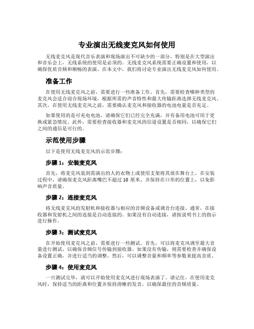
示范使用步骤以下是使用无线麦克风的示范步骤:步骤1:安装麦克风首先,将麦克风装到需演出的人的衣物上或使用支架将其放在舞台上。
在安装过程中,请确保麦克风距离嘴巴不超过10厘米,并保持在口形的位置上,以免影响声音质量。
步骤2:连接麦克风将无线麦克风的发射机和接收器与相应的音频设备或调音台连接。
通常,在接收器和发射机之间的连接是自动连接的。
如果没有自动连接,请按说明书上的指示进行操作。
步骤3:测试麦克风在开始使用麦克风之前,需要进行一些测试。
首先,可以将麦克风调至最大音量进行测试,以确保音频信号传输到接收器。
如果没有传输,则需要检查并确保设备设置正确,并进行适当的调整。
然后,可以调整音量和频率等参数来提高音质。
步骤4:使用麦克风一旦测试完毕,就可以开始使用麦克风进行现场表演了。
请记住,在使用麦克风时,保持适当的距离和位置并保持清晰的发音,以确保最佳的音频质量。
步骤5:结束使用在使用麦克风后,请记住关闭所有设备并将麦克风从演出设备上拆下。
如果使用的是可充电电池,请将其取下并重新充电以备下一次使用。
总结专业演出无线麦克风是现代音乐表演和现场演出的重要组成部分。
正确设置和使用无线麦克风系统是确保现场表演音质优质的重要因素之一。
- 1、下载文档前请自行甄别文档内容的完整性,平台不提供额外的编辑、内容补充、找答案等附加服务。
- 2、"仅部分预览"的文档,不可在线预览部分如存在完整性等问题,可反馈申请退款(可完整预览的文档不适用该条件!)。
- 3、如文档侵犯您的权益,请联系客服反馈,我们会尽快为您处理(人工客服工作时间:9:00-18:30)。
数字无线话筒使用说明书
一、手持开关机
1.将两节5号电池装入手持并拧紧网头(注意电池负极朝下,
电池装反将损坏手持),向上推开关打开手持,此时电源
指示灯亮,手持进入开机状态。
如果电源指示灯闪烁表示
电池已耗尽,请更换电池再开机。
2.向下推开关电源指示灯熄灭,手持关机。
长时间不使用话
筒请将电池取出。
二、接收机连接与开关机(专业)
1.将音频连接线一头插接收机音频输出2另一头插到用户的
音频设备(如功放、前级等)。
将12V开关电源插入220V
交流插座,输出直流12V插入接收机DCIN,蓝色电源指
示灯亮,接收机进入开机状态。
2.按住电源键一秒可以开启和关闭接收机电源。
3.断电后重新通电主机将自动进入开机状态,此时无需再按
电源键开机。
三、接收机与电脑的连接与开关机(个人)
1.将USB连接线两头分别插入电脑和接收机的USB接口。
蓝色电源指示灯,接收机进入开机状态。
电脑自动把音频
输入输出设备切换成接收机。
(首次使用接收机的时候,
电脑会自动安装驱动,电脑会依次出现图3所示的画面,
直到硬件安装成功)
2.将音频连接线一头插接收机音频输出1另一头插到用户的
桌面音响输入端。
3.此时接收机将自动成为酷我k歌或QQ等者其他应用软件
的音频输入输出设备。
(如果不能使用请参见疑难解答)
4.按住电源键一秒可以开启和关闭接收机电源。
5.断电后重新通电主机将自动进入开机状态,此时无需再按
电源键开机。
四、对码
1.接收机开机后按功能键进入A通道对码状态,电源指示灯
和A通道的射频指示灯亮,此时A通道可以对码,再按功能键进入B通道对码状态,电源指示灯和B通道射频指示灯亮,此时B通道可以对码。
再按功能键又将切换到A 通道,如此循环。
2.按照上一步将接收机切换到需要对码的通道,再按电源
键,该通道射频指示灯闪烁,此时打开任意一支手持,接收机将自动与手持实现连接,连接成功后该通道射频指示灯和音频指示灯同时亮起一秒。
说明这个通道的手持对码成功,即可使用。
3.重复步骤1和步骤2以实现另一个手持与对应通道的对
码。
五、高低功率设置(根据使用范围来选择功率的高低)
1.将接收机电源线拔除,同时按住功能键和电源键再将电源
插入主机,此时电源灯闪烁设备进入功率设置状态。
a.按功能键:手持将被设置为小功率,使用半径15m;
b.按电源键:手持将被设置为大功率,使用半径35m。
2.设置好功率后要将电源线拔除重插一次。
3.重插接收机电源查看功率的设置情况,如果A通道音频和
射频灯闪一次表示低功率,如果B通道音频和射频灯闪一
次表示高功。
七、充电
将电池放入接收机底部电池仓内,对应充电指示等会亮,开始充电,充满电之后对应充电指示灯会熄灭。
(注意每个电池仓内必须同时放入两节电池方可充电,放入一节电池将不能充电。
)
网头
LED指示
电源开关图1
图2 A 通道音频指示 A 通道射频指示 B 通道射频指示
B 通道音频指示 电源指示 音频输出1 充电指示 电源键
功能键 音频输出2 USB 接口 DC IN
1.电源指示:接收机通电开机时亮
2.射频指示:当手持和接收机连接成功是亮。
3.音频指示:对着手持讲话时根据音频强闪烁。
4.功能键:选择需要对码通道
5.音频输出1: 3.5mm 插座,接桌面多媒体音箱
6.音频输出2: 6.35mm插座,接专业设备
7.充电指示:充电时亮,充满灭。
B接口:接电脑USB接口。
9.DCIN:直流电源输入
10.电源键:开关主机电源,对码按钮。
1 2 3
4 5 6
7
图3
八.疑难解答
酷我K歌设置
11.点击“音视频设置”按钮
12.点击“麦克风”选项卡
选中声音输入设备为2.4G Wireless handset-Wave In
13.点击“扬声器”选项卡
选中声音输出设备为2.4G Wireless handset-Wave In
14.点“确定”按钮保存设置。
QQ设置
1.点击“开始语音会话”按钮右侧的下拉菜单,再点“语音设置”按钮。
2.选中声音输入设备为2.4G Wireless handset-Wave In
选中声音输出设备为2.4G Wireless handset-Wave In 3.点“确定”按钮保存设置。
技术参数
采用2.4G跳频无线数字传输技术,专业ID码加密传输,每台接收器只有唯一的ID 码,ID 编码多达百万组,彻底解决传统无线麦克风窜频干扰的现象。
同时具有自动静音功能,使用者不讲话、或处于弱信号状态时接收器完全静音。
载波频率:2400-2482MHz
调制方式:GFSK
RF输出功率:10dBm
灵敏度:-95dBm
最大距离:30米
指向性:单指向
失真度:<0.5%
信噪比:>98dB(1kHz-A)
频响范围:20HZ-20KHZ
输出阻抗600Ω
尺寸:
重量:
工作电压
发射机:DC 3V 2*AA电池供电
接收机:DC 12V
安全警告
1.为防止电击请不要打开机盖,如需拆开需有专业人士在场。
2.机器不应放在高温、多尘、潮湿、震动的地方使用
3.不要使用非原厂配件,以防止损坏。
包装清单
1.接收机1台
2.手持话筒2支
B线1条(电源适配器1个)
4.3.5mm音频线1条(6.35mm音频线1条)
5.说明书
6.保修卡
7.合格证。