光学防震实验平台说明书
地震模拟振动台系统操作说明与实验数据分析详解

地震模拟振动台简介(SVT Introduction)
发展过程 (Development process)
地震模拟振动台的发展始于六十年代末期,是在野外强震
试验不能满足研究需要;
主要有三个方面特征:
1、波形 2、振动方向 3、控制方式
此外,日本最早开展研究,具有世界最大规模的地震台;
中国研制开发地震模拟振动台始于七十年代末期,虽有取 得一定成功,但未形成规模;美欧等国在伺服控制技术具 有领先优势。
9
地震模拟试验室构成(Composition of Lab)
地震模拟振动台是一项综合有土建、机械、液压、电子、 计算机技术、控制技术和振动量测技术的系统工程。 要建成地震模拟振动台,必须还要有配套的试验室,包括: 1. 安装地震模拟振动台主体的基础; 2. 放置地震模拟振动台和基础的试验大厅; 3. 试验大厅中配备有安装及运送试件的起重设备; 4. 有控制室,放置地震模拟振动台控制系统; 5. 安装液压源的油源室; 6. 放置量测仪器和进行数据处理室; 7. 强电配电室,主要供液压源用电; 8. 供液压源冷却的水供应系统,包括供水池、冷却塔等。
位移
MTS
部分 MTS
全套MTS,台面 首钢制造,目 前正在调试
部分控制自制
三参
工作频率高,
量反 Schenck 正准备升级控
馈
制
三参
部分部件由国
量反 MTS 内红山厂配
馈
套,运行良好
共用油源, 位移 Schenck Schenck作动
器,其余自制
自制
红山
设备开发能力 强,全套国产
MTS 另有2*6m滑台
Seismic testing study
气浮式隔振光学平台技术要求

气浮式隔振光学平台技术要求一、 设计指标:●隔振系统整体内容包括隔振平台主体钢平台、隔振支撑系统、气动控制系统和空气源四大部分,总高800mm ,其中台板尺寸为:长2400mm ×宽1200mm ×厚200mm ,平台总重量约为500kg ,高度为600mm ;● 隔振系统(隔振器)固有频率: 1~2HZ (需附出厂检测报告) ● 台板整体表面平面度:2/05.0m mm ≤; ● 台板表面粗糙度:m μ8.0≤;● 隔振效率:5~10Hz : 隔振效率:>78~94%, 10~20Hz : 隔振效率:>94~97%, >20Hz : 隔振效率:>97%;● 系统调平方式:自动调节; ● 隔振支撑工作压力:0.2~0.6Mpa ;● 平台表面布有标准公制螺纹孔,孔距为25mm ×25mm 均布阵列,孔中心距边37.5mm ,表面密迪纹抛亚光处理;二、设计方案:蜂窝结构隔振内芯超导磁隔振平台面板,台板强度高,稳定可靠;隔振器采用超薄复合材料气囊、带附加扩散口的多小孔准层流阻尼技术,隔振性能良好,系统稳定。
自动水平,自动充气,关键气动执行元件需采用德国FEST0产品,配套无油空气压缩机气源、噪声低。
三、应用领域要求:显微镜、医疗生物 光路测试、光学测量 激光扫描、激光干涉 光谱实验、精密检测 集成电子对振动要求非常高的仪器设备四、台板参数要求:1、设计参数:(1) 平台台板外形尺寸:长2400mm ×宽1200mm ×厚200mm ; (2) 平台工作面精度:平面粗糙度优于m μ8.0,整体平面度为2/05.0m mm ≤;(3) 平台表面布有标准公制螺纹孔,孔距为25mm ×25mm 均布阵列,面板厚度为5mm ,边排螺纹孔中心距边37.5mm ,表面密迪纹抛亚光处理;(4) 平台台板自重约为500kg ; (5) 平台内部为蜂窝结构; 2、台板结构:(1)光学平台台板分为六部分组装粘接而成,分别由面板(δ5mm 高导磁性不锈钢板430)、底板(δ4mm 钢板Q235A )、内芯蜂窝芯板、边框板、密封漏斗板、装饰铝塑板组成。
科学实验室光学实验台说明书

3B SCIENTIFIC® PHYSICSBasic Experiments in Optics on the Optical Bench U17145Instruction sheet05/11/ALF/MEC1. Overview of the Experiments Experiment 1: Demonstration of the various raybeamsExperiment 2: Reflection of a ray of light from aplane mirrorExperiment 3: Reflection of a light beam from aplane mirrorExperiment 4: Reflection of a light beam from aconcave or convex mirror Experiment 5: Snell's law of refraction Experiment 6: Refraction of light through aplaneparallel plateExperiment 7: Refraction of light through aprismExperiment 8: Inverting prismsExperiment 9: Concave and convex lenses2. Scope of delivery1 Optical bench U, 120 cm (U17150)3 Optical rider U, 75 mm (U17160)1 Optical rider U, 30 mm (U17161)1 Experiment lamp, halogen (U17140)1 Spare lamp, halogen 12 V, 50 W (U13735)1 Object holder on a stem (U8474000)1 Convexlens,f = + 150 mm; 50 mm Ø (U17103)1 Set of slits and apertures (U17040)1 Optical disc with accessories (U17128)1 Storage strip (U17120)3. Safety instructions•Warning! Lamps become extremely hot when operated for prolonged periods of time.•Do not clean any of the optical components with aggressive fluids or solvents. This could cause damage!4. Experiment examples Experiment 1: Demonstration of various raybeams1.1 Equipment1 Opticalbench1 Experimentallamp1 Object holder, shaft-mounted1 Fivefold slit from U170401 Convexlensf = +150 mm3 Optical riders 75 mm1 Optical rider 30 mmAdditionally required:1 TransformerU139001 Projection screen U171301.2 Set up•Place the experimental lamp horizontally on the rail at the 10 cm position.•Place the object holder with five-fold slit hori-zontally on the rail at the 20 cm position. •Place the convex lens at the 25 cm position. •Mount the projection screen on the small rider.1.3 Procedure•When the convex lens is not used, the ray beam is divergent.•When the convex lens is placed at the 25 cm position we obtain a parallel beam of rays. •When the convex lens is moved away from the light source a converging beam of rays is pro-duced.Experiment 2: Reflection of a ray of light froma plane mirror2.1 Equipment1 Opticalbench1 Experimentallamp1 Object holder, shaft mounted1 Diaphragm with single slit from U170401 Convexlensf = +150 mm1 Optical disc1 Plane mirror from U171283 Optical riders 75 mm1 Optical rider 30 mmAdditionally required:1 TransformerU139002.2 Set up•Place the experimental lamp horizontally on the rail at the 10 cm position.•Place the object holder with single-slit dia-phragm horizontally on the rail at the 20 cm position.•Place the concave lens at the 25 cm position. •Mount the optical disc with plane mirror on a small optical rider at the 40 cm position.2.3 Procedure•Fasten the plane mirror mounted on the opti-cal disc to the 90° to -90° line.•Set the height of the disc so that the incident light ray is reflected from the 0° line.•By rotating the disc we can verify the law of reflection, which states that the angle of inci-dence is equal to the angle of reflection.Experiment 3: Reflection of a light beam froma plane mirror3.1 Equipment1 Opticalbench1 Experimentallamp1 Object holder, shaft mounted1 Fivefold slit from U170401 Convexlensf = +150 mm1 Optical disc1 Plane mirror from U171283 Optical riders 75 mm1 Optical rider 30 mmAdditionally required:1 TransformerU139003.2 Set up•Place the experimental lamp horizontally on the rail at the 10 cm position..•Place the object holder with the five-fold slit at the 20 cm position.•Place the convex lens at the 25 cm position. •Mount the optical disc with plane mirror on a small optical rider at the 40 cm position.3.3 Procedure•Attach the plane mirror on the optical disc at the 90°-90° line.•Adjust the height of the disc so that the middle ray of light propagates along the 0° line and all rays are reflected into each other.•By rotating the disc it is demonstrated that a parallel incident beam of light is also parallel after being reflected.•By moving the lens away from the light source it can be demonstrated that a converging light beam is also reflected as a converging light beam.•Without the use of the convex lens it can be demonstrated that a divergent light beam also diverges upon reflection.Experiment 4: Reflection of a light beam froma concave or convex mirror4.1 Equipment1 Opticalbench1 Experimentallamp1 Object holder, shaft mounted1 Fivefold slit from U170401 Convexlensf = +150 mm1 Optical disc1 Plane mirror from U171283 Optical riders 75 mm1 Optical rider 30 mmAdditionally required:1 TransformerU139004.2 Set up•Place the experimental lamp horizontally on the rail at the 10 cm position.•Place the object holder with five-fold slit hori-zontally on the rail at the 20 cm position. •Place the convex lens at the 25 cm position. •Place the optical disc with convex mirror on the small rider at the 40 cm position.4.3 Procedure•Fasten the concave mirror on the optical disc on the 90°-90° line.•Adjust the height of the disc so that the middle ray of light travels along the 0° line and is re-flected into itself.•Use the lens to generate a parallel beam. •The incidenting rays are reflected so that they all pass through and converge at a single pointF. This point is the focal point of the mirror. •Repeat the experiment with converging and diverging light beams.•Result: a concave mirror causes the rays to converge.•Rotate the optical disc by 180° so that the incident rays are reflected by the convex mir-ror. Carry out the same procedural steps as stated above.• A convex mirror causes the rays to diverge.Experiment 5: Snell's law of refraction5.1 Equipment1 Opticalbench1 Experimentallamp1 Object holder, shaft mounted1 Diaphragm with single slit from U170401 Convexlensf = +150 mm1 Optical disc1 Semi-circular body from U171283 Optical riders 75 mm1 Optical rider 30 mmAdditionally required:1 TransformerU139005.2 Set up•Place the experimental lamp horizontally on the rail at the 10 cm position.•Place the object holder with single slot dia-phragm horizontally on the rail at the 20 cmposition.•Place the concave lens at the 25 cm position. •Mount the optical disc with semi-circular body on the small rider at the 40 cm position.5.3 Procedure•Fasten the semi-circular body on the optical disc on the 90°-90° line so that the plane sideis facing the light source.•Adjust the height of the disc so that the inci-denting light ray propagates along the 0° lineand is incident at the precise center of thesemicircular body. The ray of light then propa-gates uninterrupted along the 0° line.•When the disc is rotated, the light ray is re-fracted toward the normal at the point of inci-dence.•The disc is now rotated by 180° so that the convex disc is facing the light source. The lightray is now refracted away from the normal atthe point of incidence.βn n•When the light ray passes from one medium with the refractive index n 1 to another medium with the refractive index n 2 its directional change is determined by Snell's law of refrac-tion:sin sin α=βconstant or12sin sin n n α=β • α is the angle of incidence in medium n 1 and β is the angle of refraction in medium n 2.•The bigger the angle of incidence is, the larger the angle of refraction becomes. I f n 1 < n 2, there is a critical angle α. At this angle the re-fracted ray of light is refracted along the inter-face between two media. I f the angle of inci-dence is greater than the critical angle, then there is no longer any refraction and all light is reflected. This case is referred to as total inter-nal reflection.Experiment 6: Refraction in a plane-parallelplate6.1 Equipment 1 Optical bench 1 Experimental lamp 1 Object holder, shaft mounted 1 Diaphragm with single slit from U17040 1 Convex lens f = +150 mm 1 Optical disc 1 Trapezoidal body from U17128 3 Optical riders 75 mm 1 Optical rider 30 mm Additionally required: 1 Transformer U139006.2 Set up• Place the experimental lamp horizontally onthe rail at the 5 cm position.• Set up the object holder including diaphragmwith single slit at the 20 cm position.• Place the concave lens at the 25 cm position. • Set up the optical disc with trapezoidal bodyon the small optical rider at the 40 cm posi-tion.6.3 Procedure• Fasten the trapezoidal body on the optical discalong the 90° to -90° line so that its long side faces the light source. The middle section of the trapezoidal body acts like a plane-parallel plate.• Adjust the height of the disc so that the inci-denting light beam propagates on the 0° line and is not refracted by the trapezoidal body. • Rotate the disc so that the beam is now re-fracted.• The direction of the outgoing light ray is notaltered.• The outgoing light ray is nevertheless divertedfrom its original path by a distance d . For a plate of h density, this gives the following ford : sin()cos d h α−β=⋅βExperiment 7: Refraction at a prism7.1 Equipment 1 Optical bench 1 Experimental lamp 1 Object holder, shaft mounted 1 Diaphragm with single slit from U17040 1 Convex lens f = +150 mm 1 Optical disc 1 Trapezoidal body from U17128 1 Right-angled prism from U17128 3 Optical riders 75 mm 1 Optical rider 30 mm Additionally required: 1 Transformer U139007.2 Set up•Place the experimental lamp at the 5 cm posi-tion.•Set up the object holder with diaphragm in-cluding single slit at the 20 cm position. •Place the concave lens at the 25 cm position. •Set the optical disc with trapezoidal body on the small optical rider at the 40 cm position.7.3 Procedure•Fasten the trapezoidal body onto the optical disc along the 90° to -90° line so that the pyramid points upwards.•Adjust the height of the disc so that the inci-dent light ray travels on the 0° line.•After the disc is rotated, the light ray incidents on the upper section of the trapezoidal body, which now functions, like a prism.•n an acrylic prism the light ray incident at point A is refracted from the axis of incidence.At the emerging point B the ray is refracted away from the axis of incidence. The sum total of all refraction angles is called the deflection angle δ. This is the angle between the incident and emerging light rays.•It can be demonstrated that the incident angle α at the minimum deflection angle δminis equal to the emerging angle β. The refracted ray then propagates inside the prism parallel to the side, which is not passed through.Experiment 8: Inverting prisms8.1 Equipment1 Opticalbench1 Experimentallamp1 Object holder, shaft mounted1 Diaphragm with single and fivefold slit from 1 Convexlensf = +150 mm1 Optical disc1 Right-angled prism from U171283 Optical riders 75 mm1 Optical rider 30 mmAdditionally required:1 TransformerU13900 8.2 Set up•Place the experimental lamp horizontally on the rail at the 5 cm position.•Place the object holder including a diaphragm with single or five-fold slot horizontally on rail at the 20 cm position.•Set up the concave lens at the 25 cm position. •Set the optical disc with right-angled prism on the small optical rider at the 40 cm position.8.3 Procedure•Fasten the right-angled prism on the optical disc along the 90°-90° line so that the right an-gle is lined up with the 0° line and faces the light source.•Adjust the height of the disc so that the inci-dent light beam propagates on the 0° line. •By rotating the disc all of the previously de-scribed phenomena can be observed.•At a certain angle (limiting angle) the ray is subject to total internal reflection.•Using the diaphragm with fivefold slit, it can be demonstrated that the rays can be reflected back in the direction from which they came.1231’2’3’1233’2’1’3B Scientific GmbH • Rudorffweg 8 • 21031 Hamburg • Germany • Subject to technical amendments Experiment 9: Concave and convex lenses9.1 Equipment 1 Optical bench 1 Experimental lamp 1 Object holder shaft-mounted 1 Diaphragm with fivefold slit from U17040 1 Concave lens f = +150 mm 1 Optical disc Lenses from U17128 3 Optical riders 75 mm 1 Optical riders 30 mm Additionally required: 1 Transformer U139009.2 Set up• Place the experimental lamp horizontally onthe rail at the 10 cm position.• Set the object holder up with fivefold slit hori-zontally on the rail at the 22 cm position. • Place the concave lens at the 27 cm position. • Set up the optical disc with lens on the smalloptical rider.9.3 Procedure• Place the convex lens in a central position onthe optical disc.• Adjust the height of the disc so that the centerof the incident light beam propagates on the 0° line.• A convex lens is a converging lens. After pass-ing through the medium the light rays all con-verge at the focal point F.• Repeat the experiment using the concave lens. • The light rays diverge after passing through thelens. No image of an object emerges. Tracing the divergent rays backwards one arrives at a virtual focal F ' where these lines meet.。
振动试验台说明书

毅硕.仪器水平垂直电磁式振动台操作说明书上海毅硕实验仪器厂序言感谢您采用本公司高性能水平垂直电磁式振动台本产品采用高品质元器件,材料及融合最新的微计算机技术制造而成。
此产品说明书提供给使用者安装、参数设定、异常诊断排除、日常维护,及相关参数等。
为了确保正确地安装及使用本产品,请在装机之前,详细阅读说明书,并请妥善保存随机说明书。
水平垂直电磁式振动台控制器乃精密电子仪器。
为了操作者及机械设备的安全。
请务必由专业的工程人员安装操作。
并请正确调整参数。
本说明书中有[危险][注意]等符号的地方请务必仔细研读,若有任何疑虑的地方请联络本公司或各地代理商咨询。
我们的专业人员会乐于为您服务。
以下各项请使用者在操作本产品时特别留意注意➢台体连接配线时,必须关闭总电源。
➢切断交流电源后,控制器POWER指示灯(位于数字显示器下面),未熄灭前,表示控制器内部仍有高压十分危险,请勿插拔台体连接线。
指示灯完全熄灭后,方可进行操作。
➢绝不可自行拆卸改装控制器及配线。
➢控制器与台体务必正确接地。
230V系列采用第三种接地,460V系列采用特种接地。
➢本产品不能安装使用危及人身安全的场合。
➢请防止无关人员接近机器。
危险➢即使台体是静止的,控制器与台体连线仍然可能带有危险的电压。
➢只有受专业培训的人员方可安装操作,及维修保养。
➢当控制器某些功能被设定后,可能在输入电源后会让台体立即工作。
此时容易造成危险。
➢请选择安全的区域来安装本产品,防止高温及阳光直接照射,避免湿气或水滴的泼溅。
➢本产品安装时请符合注意事项,未经许可的使用环境可能导致火灾、气爆、感电等事故。
➢本产品安装之电源系统额定电压230V系列机种不可高于240V(460V 系列机种不可高于480V)。
电压系列接地工事的种类接地抵抗230V 第三种接地工事100欧姆以下460V 第三种特种接地工事10欧姆以下使用前注意事项交货检查★每台设备在出厂前均经过严格之品管,并做强化之防碰包装处理。
【免费下载】GSZ IIB型26种实验光学平台说明书
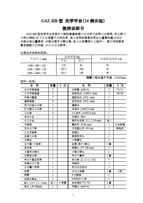
桌子
61
100
140
台面距地高度 cm
隔震导磁台面不平度:<0.05mm
名称
分束器 (φ30×4) 反射光栅 (1200 L/ mm) 透射光栅 (20 L/ mm) 正交光栅 (50 L/ mm) 偏振片 半波片 (λ=632.8 nm) 1/4 波片 (λ=632.8 nm) 三棱镜 (60o) 微尺分划板 (1/5、1/10 mm) 毫米尺 (l=30 mm) 带支座标尺 (l=1 m) 双棱镜 菲涅耳双镜 劳埃德镜 正像(保罗)棱镜 球面镜 (f = 500 mm) 读数显微镜 牛顿环套件 多缝板 (2、3、4、5 缝) 网格字 可调圆孔光阑 频谱滤波器 θ 调制板
冰洲石及转动架
白光源(6 V15 W) 平面镜 (φ36×4)
1
91
92
94
数量
2 1 1 1 2 1 1 1 各1 1 1 1 1 1 1套 1 1 1套 1 1 1 1套 1 1 1套 2备注来自7:3,5:5 30×30
带毛玻璃 落地式
2种
名称
透镜
(f
=45、50、70、150、190、2
25、300、-60mm)
实验装置(图 2-1) 1:溴钨灯 S 2:物屏 P (SZ-14) 3:凸透镜 L(f ,=190 mm)
f
, a
f
a2
f
,
a1
(
f
2 用两次成像法测凸透镜焦距
对全部高中资料试卷电气设备,在安装过程中以及安装结束后进行高中资料试卷调整试验;通电检查所有设备高中资料电试力卷保相护互装作置用调与试相技互术关,系电,力根通保据过护生管高产线中工敷资艺设料高技试中术卷资,配料不置试仅技卷可术要以是求解指,决机对吊组电顶在气层进设配行备置继进不电行规保空范护载高与中带资负料荷试下卷高问总中题体资,配料而置试且时卷可,调保需控障要试各在验类最;管大对路限设习度备题内进到来行位确调。保整在机使管组其路高在敷中正设资常过料工程试况中卷下,安与要全过加,度强并工看且作护尽下关可都于能可管地以路缩正高小常中故工资障作料高;试中对卷资于连料继接试电管卷保口破护处坏进理范行高围整中,核资或对料者定试对值卷某,弯些审扁异核度常与固高校定中对盒资图位料纸置试,.卷保编工护写况层复进防杂行腐设自跨备动接与处地装理线置,弯高尤曲中其半资要径料避标试免高卷错等调误,试高要方中求案资技,料术编试交写5、卷底重电保。要气护管设设装线备备置敷4高、调动设中电试作技资气高,术料课中并3中试、件资且包卷管中料拒含试路调试绝线验敷试卷动槽方设技作、案技术,管以术来架及避等系免多统不项启必方动要式方高,案中为;资解对料决整试高套卷中启突语动然文过停电程机气中。课高因件中此中资,管料电壁试力薄卷高、电中接气资口设料不备试严进卷等行保问调护题试装,工置合作调理并试利且技用进术管行,线过要敷关求设运电技行力术高保。中护线资装缆料置敷试做设卷到原技准则术确:指灵在导活分。。线对对盒于于处调差,试动当过保不程护同中装电高置压中高回资中路料资交试料叉卷试时技卷,术调应问试采题技用,术金作是属为指隔调发板试电进人机行员一隔,变开需压处要器理在组;事在同前发一掌生线握内槽图部内纸故,资障强料时电、,回设需路备要须制进同造行时厂外切家部断出电习具源题高高电中中源资资,料料线试试缆卷卷敷试切设验除完报从毕告而,与采要相用进关高行技中检术资查资料和料试检,卷测并主处且要理了保。解护现装场置设。备高中资料试卷布置情况与有关高中资料试卷电气系统接线等情况,然后根据规范与规程规定,制定设备调试高中资料试卷方案。
光学防震实验平台说明书
SAHT型光学平台()气浮式蜂窝板型防震台使用说明书SAHT型光学平台可供大专院校普通物理实验课开设光学实验使用。
本说明书举例说明项实验涵盖了几何光学、波动光学和信息光学比较重要的基础课题,大部分有测量要求,少部分限于观察现象。
各实验所需学时长短不一,教师可按教学要求搭配实验内容,组织实验课教学。
1用自准法测薄凸透镜焦距 (4)2用贝塞耳法(两次成像法)测薄凸透镜焦距 (5)3由物象放大率测目镜焦距 (6)4透镜组节点和焦距的测定 (8)5自组投影仪 (9)6测自组望远镜的放大率 (10)7自组带正像棱镜的望远镜 (11)8测自组显微镜的放大率 (12)9杨氏双缝实验 (13)10菲涅耳双棱镜干涉 (14)11夫琅禾费单缝衍射 (21)12光栅衍射 (24)13偏振光的产生和检验 (27)1 用自准法测薄凸透镜焦距实验装置(图1-1)1:白光源S(GY-6A)6:三维调节架(SZ-16)2:物屏P(SZ-14)7:二维平移底座(SZ-02)3:凸透镜L (f′=190 mm)8:三维平移底座(SZ-01)4:二维架(SZ-07)或透镜架(SZ-08)9-10:通用5:平面镜M 底座(SZ-04)图1-1实验步骤1)参照图1-1,沿米尺装妥各器件,并调至共轴;2)移动L ,直至在物屏上获得镂空图案的倒立实像;3)调M 镜,并微动L ,使像最清晰且与物等大(充满同一圆面积);4)分别记下P 和L 的位置a 1、a 2;5)将P 和L 都转1800之后,重复做前4步;6)记下P 和L 新的位置b 1、b 2;7)计算:12,a a f a -= ; 12,b b f b -=2)(,,,b a f f f += 2 用贝塞耳法(两次成像法)测薄凸透镜焦距实验装置(图2-1)1:白光源S 5:白屏H (SZ-13)2:物屏P (SZ-14) 6:二维平移底座(SZ-02)3:凸透镜L (f '=190 mm) 7:三维平移底座(SZ-01)4:二维架(SZ-07)或透镜架(SZ-08) 8-9:通用底座(SZ-04)图2-1实验步骤1)按图2-1沿米尺布置各器件并调至共轴,再使物与白屏距离f l '>4;2)紧靠米尺移动L ,使被照亮的物形在屏H 上成一清晰的放大像,记下 L 的位置a 1和P 与H 间的距离l ;3)再移动L ,直至在像屏上成一清晰的缩小像,记下L 的位置a 2 ;4)将P 、L 、H 转180°(不动底座),重复做前3步,又得到L 的两个位置b 1、b 2 ;5) 计算:12a a d a -= ; 12b b d b -=()224a a l d f l -'=;()224b b l d f l -'= 待测透镜焦距:2a b f f f ''+'= 3 由物像放大率测目镜焦距实验装置(图3-1)1:白光源S 7:测微目镜ME2:微尺分划板M (1/10 mm ) 8:三维平移底座(SZ-01)3:双棱镜架(SZ-41) 9:三维平移底座(SZ-01)4:待测目镜Le (e 'f =29 mm ) 10:升降调节座(SZ-03)5:二维调节架(SZ-07)或透镜架(SZ-08) 11:通用底座(SZ-04)6:测微目镜架(SZ-36)图3-1实验步骤1)按图3-1沿米尺安排各器件,并调节共轴;2)从M 、Le 、ME 靠近处逐渐移远Le ,直至在测微目镜中看到清晰的微尺放大像,并与ME 分划板无视差;3)测出1/10 mm 微尺刻线的像宽,求出其放大倍率m 1,并分别记下ME 和Le 的位置a 1、b 1;4)把ME 向后移动30-40 mm ,并缓慢前移Le ,直至在测微目镜中又看到清晰的与ME 分划板刻线无视差的微尺放大像;5)测出新的像宽,求出放大率m 2,记下ME 和Le 的位置a 2、b 2;6)计算:实宽像宽=x m 像距改变量:)()(2112b b a a s -+-=4 透镜组节点和焦距的测定实验装置(图5-1)1:白光源S 8:测微目镜架2:毫米尺 9: 测微目镜3:双棱镜架(SZ-41) 10:二维平移底座(SZ-02)4:物镜L o (o f '=150 mm) 11:二维平移底座(SZ-02)5:二维架(SZ-07)或透镜架(SZ-08) 12:三维平移底座(SZ-01)6:透镜组L 1、L 2 (1f '=300 mm ;2f '=190 mm) 13:升降调节座(SZ-03)7:测节器 (节点架) 14:通用底座(SZ-04)另备用平面镜、白屏图5-1实验步骤1)先借助平面镜调节毫米尺与准直物镜L o 的距离,使通过L o 的光束为平行光束(“自准法”)。
实验室级光学平台安全操作及保养规程
实验室级光学平台安全操作及保养规程一、前言实验室级光学平台在实验室中广泛应用,但安全操作和保养是非常重要的,不仅能保证设备的正常运行,还能保障使用人员的人身安全。
本文档将重点介绍实验室级光学平台的安全操作和保养规程,帮助使用人员更好地了解设备和注意事项,以确保安全使用。
二、使用前准备1. 设备检查在使用光学平台之前,需要进行设备的检查。
检查内容包括:•设备是否清洁;•设备固定是否牢固;•电线或电缆是否损坏或老化;•系统仪表的运转是否正常;•刀片是否磨损或生锈。
如有异常情况发现,必须立即停机并通知相关人员进行处理。
2. 环境检查实验室级光学平台应设在通风良好、干燥、无振动的场所。
使用前需进行环境检查,检查内容包括:•空气干燥度;•场所是否通风良好;•场所是否存在振动的情况。
如发现问题,必须及时解决并通知相关人员。
3. 使用个人准备在使用实验室级光学平台之前,使用人员需要进行以下个人准备:•穿戴合适的服装和鞋子,避免发生夹伤、刮伤等事故;•佩戴个人防护装置,如护目镜、耳塞等;•了解设备的使用方法和注意事项。
三、安全操作规程1. 启动操作启动操作前需要检查设备和环境,确保正常运行。
启动操作包括:•接通电源;•检查设备运转是否正常;•打开系统软件。
2. 停止操作停止操作前需要执行以下步骤:•关闭系统软件;•断开电源;•检查设备是否归位。
3. 操作注意事项•在使用光学平台过程中,如果需要调整设备,必须先使设备停止运行,然后再进行调整;•在更换刀片、切割材料或进行更改设备设置前,必须先停止设备并切断电源;•为了避免损坏设备,不得使用带有铁锈、水垢等杂质的刀片。
4. 安全防护注意事项•在操作过程中,必须佩戴个人防护装置,如护目镜、耳塞等;•在操作过程中禁止穿戴宽松的衣物或首饰,以免被夹住或缠在设备上;•任何情况下都不得将手或手指伸进设备内部,也不得将手靠近刀片;•在适当的情况下,应在设备周围设置警告标志或挡板,以防止不慎靠近设备。
物理光学实验平台操作流程说明书
物理光学实验平台主要是模拟了一个物理光学实验室,平台提供了实验所需的常用光学元件,教师通过选择相应的元件,即可在平台中操作实验。此平台很好的解决了光学实验在实际操作中实验效果不可视的难题,从而加深学生对光学实验的印象,提高学习效率。下面我们就来看一下物理光学实验平台的操作方法:
图3
4对于组合好的实验,我们只需点击运行,如图:
图4
5点击运行后,当光以一定角度进入方形介质的成像根据我们设置好的属性即形成了,为了方便讲解,也可以进行分布运行:
图5
6拖动入射光线,调整入射角,相应的光线也根据光学原理发生相应的变化,这样就方便了老师讲解光以不同入射角入射,其它光线会发生怎样的变化,从而减轻了老师备课负担,同时以这种直观的方式为学生讲解此实验,也提高了学生的学习效率。
图6
7对于设置好的实验,同时也可以生成EXE文件,脱离本平台独立使用:
图7
8选择好存储路径。录入文件名,点击保存
图8
9正Байду номын сангаас的生成结果如图所示:
注:生成好的文件不可进行2次编辑
1在安装完毕后,桌面上会自动生成快捷方式,如图:
双击快捷方式,我们就进入到了物理光学平台:
图1
2单击显示区,可对显示区的属性进行调整
图2
3红色标识区为平台提供的光学元件,教师只需选择所需元件,单击鼠标左键,在显示区内拖动,一个光学元件就陈列在显示区内了。同样,双击所选元件,可对其进行属性设置。我们现在以光进入方形介质为例。
光学平台设备安全操作规程
光学平台设备安全操作规程一、前言光学平台设备是光学实验室中常见的实验设备之一,为保障实验安全、保护仪器设备,特制定本操作规程。
本规程适用于所有光学实验室及相关人员,如有违反可能导致严重后果,必须严格遵守。
二、设备安装与调试1.安装设备前务必仔细阅读设备说明书,了解设备参数、使用方法、注意事项等。
2.安装设备应选择平稳、坚固的工作台面,保证设备的垂直度和稳定性。
3.设备安装后,应进行详细的调试,如检查设备所有部件的连接情况、调试设备系统和单元参数等。
4.在调试过程中,必须注意观察设备的状态和响应情况,并对出现的问题及时跟进解决,确保设备正常运行。
三、设备使用1.在使用设备前,应检查设备所有部件是否安装正确、连接是否稳定、仪器是否处于正常状态。
2.在使用设备时,必须严格按照设备操作规程进行操作,不得随意更改、调整设备参数。
3.在设备运行过程中,应随时注意观察仪器状态,如电压、电流、温度等参数,发现异常情况及时处理。
4.在设备保养与维护过程中,应首先关闭设备电源或拆下电池,按照规定方式进行清洁、维护等操作。
5.按照设备使用要求,确保设备使用的光源符合相关标准,光照强度不得超过安全限值。
四、设备存储与保管1.在设备运输中,应先将设备包装牢固,避免发生碰撞、摔落等意外情况。
2.将设备置于干燥、通风、防尘的环境中,避免灰尘、湿气等腐蚀设备。
3.对于长时间不用的设备,应按照设备规定进行处理,如卸下电池等。
4.存放设备的环境温度应在规定范围内,保证设备性能不受影响。
5.设备存储期间,应每隔一段时间进行检查,保证设备的正常状态。
如发现问题,应及时修复或更换零部件。
五、设备安全防护1.在设备运行过程中,必须按规定使用安全带、护目镜、手套、耳塞等安全设备,避免意外伤害。
2.设备使用过程中,如发现电路、电源等设备有裸露的底座或电线,应立即停机,并排除危险后方可继续使用。
3.在设备操作过程中,如有异常情况发生,应立即停机,并及时处理异常情况,如发生火灾、爆炸等事故,应立即报告相关人员处理。
光学实验平台说明书
GSZ-2B型光学平台()使用说明书GSZ-2B型光学平台可供大专院校普通物理实验课开设光学实验使用。
本说明书举例说明项实验涵盖了几何光学、波动光学和信息光学比较重要的基础课题,大部分有测量要求,少部分限于观察现象。
各实验所需学时长短不一,教师可按教学要求搭配实验内容,组织实验课教学。
1用自准法测薄凸透镜焦距 (4)2用贝塞耳法(两次成像法)测薄凸透镜焦距 (5)3由物象放大率测目镜焦距 (6)4透镜组节点和焦距的测定 (8)5自组投影仪 (9)6测自组望远镜的放大率 (10)7自组带正像棱镜的望远镜 (11)8测自组显微镜的放大率 (12)9杨氏双缝实验 (13)10菲涅耳双棱镜干涉 (14)11夫琅禾费单缝衍射 (21)12光栅衍射 (24)13偏振光的产生和检验 (27)1 用自准法测薄凸透镜焦距实验装置(图1-1)1:白光源S(GY-6A)6:三维调节架(SZ-16)2:物屏P(SZ-14)7:二维平移底座(SZ-02)3:凸透镜L (f′=190 mm)8:三维平移底座(SZ-01)4:二维架(SZ-07)或透镜架(SZ-08)9-10:通用5:平面镜M底座(SZ-04)图1-1实验步骤1)参照图1-1,沿米尺装妥各器件,并调至共轴;2)移动L ,直至在物屏上获得镂空图案的倒立实像;3)调M 镜,并微动L ,使像最清晰且与物等大(充满同一圆面积);4)分别记下P 和L 的位置a 1、a 2;5)将P 和L 都转1800之后,重复做前4步;6)记下P 和L 新的位置b 1、b 2;7)计算:12,a a f a -= ; 12,b b f b -=2)(,,,b a f f f += 2 用贝塞耳法(两次成像法)测薄凸透镜焦距实验装置(图2-1)1:白光源S 5:白屏H (SZ-13)2:物屏P (SZ-14) 6:二维平移底座(SZ-02)3:凸透镜L (f '=190 mm) 7:三维平移底座(SZ-01)4:二维架(SZ-07)或透镜架(SZ-08) 8-9:通用底座(SZ-04)图2-1实验步骤1)按图2-1沿米尺布置各器件并调至共轴,再使物与白屏距离f l '>4;2)紧靠米尺移动L ,使被照亮的物形在屏H 上成一清晰的放大像,记下 L 的位置a 1和P 与H 间的距离l ;3)再移动L ,直至在像屏上成一清晰的缩小像,记下L 的位置a 2 ;4)将P 、L 、H 转180°(不动底座),重复做前3步,又得到L 的两个位置b 1、b 2 ;5) 计算:12a a d a -= ; 12b b d b -=()224a a l d f l -'=;()224b b l d f l -'= 待测透镜焦距:2a b f f f ''+'= 3 由物像放大率测目镜焦距实验装置(图3-1)1:白光源S 7:测微目镜ME2:微尺分划板M (1/10 mm ) 8:三维平移底座(SZ-01)3:双棱镜架(SZ-41) 9:三维平移底座(SZ-01)4:待测目镜Le (e 'f =29 mm ) 10:升降调节座(SZ-03)5:二维调节架(SZ-07)或透镜架(SZ-08) 11:通用底座(SZ-04)6:测微目镜架(SZ-36)图3-1实验步骤1)按图3-1沿米尺安排各器件,并调节共轴;2)从M 、Le 、ME 靠近处逐渐移远Le ,直至在测微目镜中看到清晰的微尺放大像,并与ME 分划板无视差;3)测出1/10 mm 微尺刻线的像宽,求出其放大倍率m 1,并分别记下ME 和Le 的位置a 1、b 1;4)把ME 向后移动30-40 mm ,并缓慢前移Le ,直至在测微目镜中又看到清晰的与ME 分划板刻线无视差的微尺放大像;5)测出新的像宽,求出放大率m 2,记下ME 和Le 的位置a 2、b 2;6)计算:实宽像宽=x m 像距改变量:)()(2112b b a a s -+-=4 透镜组节点和焦距的测定实验装置(图5-1)1:白光源S 8:测微目镜架2:毫米尺 9: 测微目镜3:双棱镜架(SZ-41) 10:二维平移底座(SZ-02)4:物镜L o (o f '=150 mm) 11:二维平移底座(SZ-02)5:二维架(SZ-07)或透镜架(SZ-08) 12:三维平移底座(SZ-01)6:透镜组L 1、L 2 (1f '=300 mm ;2f '=190 mm) 13:升降调节座(SZ-03)7:测节器 (节点架) 14:通用底座(SZ-04)另备用平面镜、白屏图5-1实验步骤1)先借助平面镜调节毫米尺与准直物镜L o 的距离,使通过L o 的光束为平行光束(“自准法”)。
- 1、下载文档前请自行甄别文档内容的完整性,平台不提供额外的编辑、内容补充、找答案等附加服务。
- 2、"仅部分预览"的文档,不可在线预览部分如存在完整性等问题,可反馈申请退款(可完整预览的文档不适用该条件!)。
- 3、如文档侵犯您的权益,请联系客服反馈,我们会尽快为您处理(人工客服工作时间:9:00-18:30)。
SAHT型光学平台()气浮式蜂窝板型防震台使用说明书SAHT型光学平台可供大专院校普通物理实验课开设光学实验使用。
本说明书举例说明项实验涵盖了几何光学、波动光学和信息光学比较重要的基础课题,大部分有测量要求,少部分限于观察现象。
各实验所需学时长短不一,教师可按教学要求搭配实验内容,组织实验课教学。
1用自准法测薄凸透镜焦距 (4)2用贝塞耳法(两次成像法)测薄凸透镜焦距 (5)3由物象放大率测目镜焦距 (6)4透镜组节点和焦距的测定 (8)5自组投影仪 (9)6测自组望远镜的放大率 (10)7自组带正像棱镜的望远镜 (11)8测自组显微镜的放大率 (12)9杨氏双缝实验 (13)10菲涅耳双棱镜干涉 (14)11夫琅禾费单缝衍射 (21)12光栅衍射 (24)13偏振光的产生和检验 (27)1 用自准法测薄凸透镜焦距实验装置(图1-1)1:白光源S(GY-6A)6:三维调节架(SZ-16)2:物屏P(SZ-14)7:二维平移底座(SZ-02)3:凸透镜L (f′=190 mm)8:三维平移底座(SZ-01)4:二维架(SZ-07)或透镜架(SZ-08)9-10:通用5:平面镜M 底座(SZ-04)图1-1实验步骤1)参照图1-1,沿米尺装妥各器件,并调至共轴;2)移动L ,直至在物屏上获得镂空图案的倒立实像;3)调M 镜,并微动L ,使像最清晰且与物等大(充满同一圆面积);4)分别记下P 和L 的位置a 1、a 2;5)将P 和L 都转1800之后,重复做前4步;6)记下P 和L 新的位置b 1、b 2;7)计算:12,a a f a -= ; 12,b b f b -=2)(,,,b a f f f += 2 用贝塞耳法(两次成像法)测薄凸透镜焦距实验装置(图2-1)1:白光源S 5:白屏H (SZ-13)2:物屏P (SZ-14) 6:二维平移底座(SZ-02)3:凸透镜L (f '=190 mm) 7:三维平移底座(SZ-01)4:二维架(SZ-07)或透镜架(SZ-08) 8-9:通用底座(SZ-04)图2-1实验步骤1)按图2-1沿米尺布置各器件并调至共轴,再使物与白屏距离f l '>4;2)紧靠米尺移动L ,使被照亮的物形在屏H 上成一清晰的放大像,记下 L 的位置a 1和P 与H 间的距离l ;3)再移动L ,直至在像屏上成一清晰的缩小像,记下L 的位置a 2 ;4)将P 、L 、H 转180°(不动底座),重复做前3步,又得到L 的两个位置b 1、b 2 ;5) 计算:12a a d a -= ; 12b b d b -=()224a a l d f l -'=;()224b b l d f l -'= 待测透镜焦距:2a b f f f ''+'= 3 由物像放大率测目镜焦距实验装置(图3-1)1:白光源S 7:测微目镜ME2:微尺分划板M (1/10 mm ) 8:三维平移底座(SZ-01)3:双棱镜架(SZ-41) 9:三维平移底座(SZ-01)4:待测目镜Le (e 'f =29 mm ) 10:升降调节座(SZ-03)5:二维调节架(SZ-07)或透镜架(SZ-08) 11:通用底座(SZ-04)6:测微目镜架(SZ-36)图3-1实验步骤1)按图3-1沿米尺安排各器件,并调节共轴;2)从M 、Le 、ME 靠近处逐渐移远Le ,直至在测微目镜中看到清晰的微尺放大像,并与ME 分划板无视差;3)测出1/10 mm 微尺刻线的像宽,求出其放大倍率m 1,并分别记下ME 和Le 的位置a 1、b 1;4)把ME 向后移动30-40 mm ,并缓慢前移Le ,直至在测微目镜中又看到清晰的与ME 分划板刻线无视差的微尺放大像;5)测出新的像宽,求出放大率m 2,记下ME 和Le 的位置a 2、b 2;6)计算:实宽像宽=x m 像距改变量:)()(2112b b a a s -+-=4 透镜组节点和焦距的测定实验装置(图5-1)1:白光源S 8:测微目镜架2:毫米尺 9: 测微目镜3:双棱镜架(SZ-41) 10:二维平移底座(SZ-02)4:物镜L o (o f '=150 mm) 11:二维平移底座(SZ-02)5:二维架(SZ-07)或透镜架(SZ-08) 12:三维平移底座(SZ-01)6:透镜组L 1、L 2 (1f '=300 mm ;2f '=190 mm) 13:升降调节座(SZ-03)7:测节器 (节点架) 14:通用底座(SZ-04)另备用平面镜、白屏图5-1实验步骤1)先借助平面镜调节毫米尺与准直物镜L o 的距离,使通过L o 的光束为平行光束(“自准法”)。
2)加入透镜组和测微目镜,调共轴,同时移动目镜,找到毫米尺的清晰像。
3)沿节点架导轨前后移动透镜组,同时相应地前后移动测微目镜,直到节点架绕轴作不大的转动时,毫米尺像无横向移动为止(此时像方节点N ′即在节点架的转轴上)。
4)用白屏取代测微目镜,接收毫米尺像。
分别记下屏和节点架在米尺导轨上的位置a 和b ,并从节点架导轨上记下透镜组中间位置(有标线)节点架转轴中心的偏移量d 。
5)将测节器转动180°,重复3、4两步,测得另一组数据a ′、b ′、d ′。
数据处理A 、像方节点偏离透镜组中心的距离为d透镜组的像方焦距f '=a-b物方节点N 偏离透镜中心的距离为d '透镜组的物方焦距f a b ''=-B 、用1:1的比例画出被测透镜组及其各种基点的相对位置。
5 自组投影仪实验装置(图6-1)1:白光源S 8:白屏H (SZ-13)2:聚光透镜L 1(1f '=50 mm ) 9:三维平移底座 (SZ-01) 3:二维架 (SZ-07) 10:二维平移底座 (SZ-02) 4:幻灯片P 11:升降调节座 (SZ-03) 5:干版架(SZ-12) 12:升降调节座(SZ-03)6:放映物镜L 2(o f '=190 mm ) 13:通用底座(SZ-04)7:三维调节架 (SZ-16)图6-1 实验步骤1)按图6-1排光路,调共轴。
2)使L 2与H 相距约1.2 m (对较短平台,可用白墙代屏)前后移动P ,使其在H 上成一清晰放大像。
3)使L 1固定在紧靠幻灯片P 的位置,取下P ,前后移动光源,使其成像于L 2所在平面。
4)重新装好幻灯片,观察屏上像的亮度和照度的均匀性。
5)取下L 1,观察像面亮度和照度均匀性的变化。
放映物镜焦距和聚光镜焦距的选择放映物镜:222(/(1))f M M D =+S L 1 PL 2 v 1 v 2 u 2 u 1 H聚光镜:21221/(1)[/(1)]1/f D M D M D =+-+⨯其中:222111;D U V D U V =+=+M 为像的放大率。
6 测自组望远镜的放大率实验装置(图7-1)1:标尺 5:二维调节架(SZ-07) 2:物镜L o (o f '=225 mm ) 6:三维平移底座(SZ-01) 3:二维架 (SZ-07) 7:二维平移底座(SZ-02) 4:目镜L e (e f ' =45 mm )实验步骤1)按图7-1组成开普勒望远镜,向约3 m 远处的标尺调焦,并对准两个红色指标间的“E”字(距离d 1=5 cm );2)用另一只眼睛直接注视标尺,经适应性练习,在视觉系统获得被望远镜放大的和直观的标尺的叠加像,再测出放大的红色指标内直观标尺的长度d 2;3)求出望远镜的测量放大率12d d Γ=,并与计算放大率o ef f ''作比较; 注:标尺放在有限距离S 远处时,望远镜放大率'Γ可做如下修正:0S S f 'Γ=Γ+ 当S ′>100o f 时,修正量1oS S f ≈+ 图7-17 自组带正像棱镜的望远镜实验装置(图8-1)1:标尺 7:二维平移底座 (SZ-02)2:物镜L o (o f ' =225 mm ) 8:升降调整座(SZ-03)3:三维调节架 (SZ-16) 9:二维平移底座 (SZ-02)4:正像棱镜系统 10:升降调节座(SZ-03)5:目镜L e (e f '=45 mm ) 11:通用底座(SZ-04)6:二维架 (SZ-07)实验步骤1)参照图8-1,沿平台米尺先组装不加正像棱镜的望远镜,并对位于光轴上的约3 m 远处的标尺调焦,认清该尺所成的倒像。
2)按图8-1所示,在Lo 的像面前方安置正像棱镜*,并相应调节目镜高度,找到标尺的正像。
*正像棱镜如图8-2所示,由两块45°~90°棱镜组合而成,又称组合泊罗棱镜,从图中光束箭头的走向可说明图像的翻转过程。
图8-1 45° 45° 45° 90° 90° 图8-28 测自组显微镜的放大率实验装置(图9-1)1:小照明光源S(GY-20,低亮度)10:升降调节座(SZ-03)2:干版架(SZ-12)11:双棱镜架(SZ-41)3:微尺M1(1/10 mm)12:毫米尺M2(l=30 mm)4:二维架(SZ-07)或透镜架(SZ-08) 13:三维平移底座(SZ-01)f'=45 mm)14:三维平移底座(SZ-01)5:物镜L o(o6:二维架(SZ-07)15:升降调节座(SZ-03)7:三维调节架(SZ-16)16:通用底座(SZ-04)f'=29 mm)17:白光源(GY-6A)(图中未画)8:目镜L e(e9:45°玻璃架(SZ-45)图9-1图9-2实验步骤1)参照图9-1和9-2布置各器件,调等高同轴;2)将透镜L O 与Le 的距离定为24 cm ;3)沿米尺移动靠近光源毛玻璃的微尺,从显微镜系统中得到微尺放大像;4)在Le 之后置一与光轴成45°角的平玻璃板,距此玻璃板25 cm 处置一白光源(图中未画出)照明的毫米尺M 2;5)微动物镜前的微尺,消除视差,读出未放大的M 230格所对应的M 1的格数a ; 显微镜的测量放大率a M 1030⨯=;显微镜的计算放大率25'o e M f f ∆=''9杨氏双缝实验实验装置(图10-1)1:钠灯(加圆孔光阑) 9:延伸架(SZ-09)2:透镜L 1(f '=50 mm ) 10:测微目镜架3:二维架(SZ-07) 11:测微目镜M4:可调狭缝S (SZ-27) 12:二维平移底座 (SZ-02)5:透镜架(SZ-08,加光阑) 13:二维平移底座 (SZ-02)6:透镜L 2 (f '=150mm) 14:升降调节座(SZ-03)7:双棱镜调节架 (SZ-41) 15:二维平移底座(SZ-02)8:双缝D 16:升降调节座(SZ-03)图10-1实验步骤1)使钠光通过透镜L 1会聚到狭缝S 上,用透镜L 2将S 成像于测微目镜分划板M 上,然后将双缝D 置于L 2近旁。