林肯焊机软件介绍
林肯焊机说明书
林肯焊机说明书Ⅰ.机械安装1.机头安装安装应牢固以防起弧时机头移动,注意机头与工作电缆应与地绝缘。
根据需要,可装在垂直调节器/水平调节器/行走小车上,所定的机头出厂前根据用户的订购模式安装送丝比率,当改变焊丝直径时需改变送丝轮和导向管。
对不同直径的焊丝需调节随动轮压力调节螺丝,焊丝分两档0.9-2.4mm和3.0-5.6mm。
根据需要调节,对较软的焊丝,压力宜小一点。
出厂时送丝轮设为正转(如图所示方向),但安装板可转动180º,并对换校直器和导电杆,送丝轮转动方向通过改变控制箱内接线上626,627号线来实现。
一般用25kg送丝盘。
NA-3S/NA-4/NA-3SF出厂时所装焊丝校直器的焊丝直径大于2mm以上。
机头安装好后,通过校直器和送丝导向管安装焊丝(其入口处为倒圆)而出丝导向管入口处为倒角)。
2.控制箱安装控制箱在标准行走小车或其它的机架上,当装在其它机架上时,打开控制箱后盖,按照控制箱底板上的安装孔固定控制箱。
3.导电杆组件国内一般常用K231 和K226●K231 导电杆组件:一般用于600A,更高电流可能引起导电嘴磨损坏。
适用于Ф2.4-5.6mm,对不同焊丝需不同导电嘴。
对Ф2.0-2.4mm焊丝还需导电嘴选配件和导丝管。
把工件电缆控制接到导电杆上,用螺栓拧紧,不用完全校直焊丝,以保持良好的电接触。
把焊剂漏斗的软管接到锥形组件的开口处。
要注意经常更换坏的导电嘴。
●K226 压钳式导电杆:一般用于600-1000A。
K226-T 由两个锥形夹组成用于Ф2.4-3.2mm。
K226R由一个锥形夹和一个方形夹组成,用于Ф3.2-5.6mm。
导电杆装在机头的下部,注意锥形夹的斜坡应朝向工件移动方向。
压钳应与导向管对直,通过调节夹钳一侧的螺丝来调节。
Ⅱ.电气安装1.电缆连接需600W,115V/50AC(其中,350W 给送丝电机和控制电路,250W 给行走电路)●从机头到控制箱:所有的工件电缆都接到控制箱后部,每个机头都带1.2m 长电机电缆和1.2m 长焊剂斗电缆,插到控制箱一侧对应的接口内。
林肯V350-PRO焊机产品说明书
E5.91PC Page 2 of 2 4/00
V350-PRO’s LED’s are bright and easy to read.
V350-PRO has easier set-ups.
Yes 5 modes
Similar.
V350-PRO has custom pipe welding output.
Arc control
Yes
Yes
Yes
Vt range.
V350-PRO has input voltage flexibility to go anywhere.
at 350 Amp output V350-PRO gives
50/25 Amps
power cost savings.
No. Handles on top. Machine hits knees when carrying
17 x 12.5 x 24
Weight
77 lbs.
76 lbs.
Thermal 400 GMS
Yes
Yes, Lift-Start™
Yes
No
Yes
Plastic overhang, no door protection Exposed on front
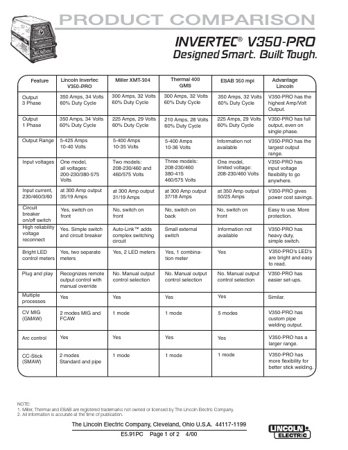
INVERTEC® V350-PRO
Designed Smart. Built Tough.
Feature
Output 3 Phase
Lincoln Invertec V350-PRO
350 Amps, 34 Volts 60% Duty Cycle
林肯电焊机操作手册说明书

SP-100OPERA TOR'S MANUALFor use with machines having Code Number 9284 and above .Sales and Service through Subsidiaries and Distributors WorldwideWorld's Leader in Welding and Cutting Products Premier Manufacturer of Industrial MotorsIM366-BNovember 1993Safety Depends on YouLincoln arc welding equipment is designed and built wit h safet y in mind. However, your overall safety can be increased by proper instal-lat ion ... and t hought ful operat ion on your part.DO NOT INSTALL OPERATE OR REPAIR THIS EQUIPMENT WITHOUT READ-ING THIS MANUAL AND THE SAFETY PRECAUTIONS CON-TAINED THROUGHOUT.And,most importantly, think before you act and be careful.9284; 9429; 9521; 9522; 9725;9726; 9794; 9795; 10050Thank Youfor selecting a QUALITY product by Lincoln Electric.We want you to take pride in operating this Lincoln Electric C ompany product ••• as much pride as we have in bringing this product to you!Read this Operators Manual completely before attempting to use this equipment. Save this manual and keep it handy for quick reference. Pay particular attention to the safety instructions we have provided for your protection. The level of seriousness to be applied to each is explained below:PRODUCT DESCRIPTIONThe SP-100, Type K462, is a complete semiautomatic constant voltage DC arc welding machine. Included is a solid state controlled, single phase constant voltage transformer/ rectifier power source and a wire feeder for feeding .023 – .030" (0.6 – 0.8 mm) solid steel electrode and .035" (0.9 mm) cored electrode.The SP-100 is ideally suited for individuals having access to 115 volt AC input power, and wanting the ease of use, quality and dependability of both gas metal arc welding or GMAW (also known as MIG welding) and the Innershield®electrode process (self-shielded flux-cored or FC AW). A convenient chart is mounted inside the wire feed section door for setting welding procedures for 24 gauge through 12 gauge (0.6 – 2.5 mm) mild steel (Chart also may be found in this manual). The SP-100 is a rugged and reliable machine that has been designed for dependable ser-vice and long life.RECOMMENDED PROCESSES AND EQUIPMENTThe SP-100 can be used for welding mild steel using the GMAW, single pass, process which requires a supply of shielding gas or it can be used for the self-shielded, Innershield electrode process.The recommended gas and electrode for GMAW is welding grade CO2gas and .025" (0.6 mm) diameter Lincoln L-56 mild-steel welding wire [supplied on 12 1/2 lb (6 kg) spools]. For 14 gauge (2.0 mm) and thin-ner, CO2gas is recommended because it gives equal or better performance than a blended gas at a lower cost. A mixed gas consisting of 75 to 80% Argon and 20 to 25% CO2is recommended for welding on heav-ier gauge [12 gauge (2.5 mm) for example] steel.The recommended electrode for the self-shielded process is .035" (0.9 mm) diameter Lincoln Innershield NR-211-MP on 10 lb (4.5 kg) spools. This electrode can be used for all position welding of 20 gauge through 5/16" (1.0 – 8.0 mm) thick steel [multi-ple passes are required for 1/4" and 5/16" (6.0 and 8.0 mm)].OPTIONAL ACCESSORIES1.K463 CO2G as Regulator and Hose Kit—Includes a preset, nonadjustable pressure and flow regulator for use on C O2cylinders. Also included is a 10 foot (3.0 m) gas hose which con-nects to the rear of the SP-100.2.K499 Ar-Mixed Gas Regulator and Hose Kit—Includes a preset, nonadjustable pressure and flow regulator for use on argon-mixed gas cylin-ders. Also included is a 10 foot (3.0 m) gas hose which connects to the rear of the SP-100.3..035 (0.9 mm) Innershield®Welding Kit —Includes a contact tip, a gasless nozzle and a cable liner to permit the SP-100 gun and cable to use a .035" (0.9 mm) diameter flux-cored elec-trode. Also included is a spool of .035 (0.9 mm) Innershield®NR-211-MP.Two kits are available:K549-1 kit is for use with the Magnum™100L gun (with red trigger).K464 kit is for use with the original Lincoln Electric®gun (with black trigger).4.M15448-1 Reversible Drive Roll with doubleknurled grooves for .035 cored electrode.5.K467 Input Line Cord — Same as line cord sup-plied with the SP-100 but has a NEMA type 5-20P plug for use on 25 amp branch circuits.To install optional features refer to instructions included with the kit, and/or in this manual.INSTALLATIONDESCRIPTION OF CONTROLSBecome familiar with the SP-100 controls and compo-nents before attempting to weld. Refer to illustrations and lettered items below for brief descriptions.A.Wire speed — Controls the wire speed from 50 –400 in./min (1.3 – 10 m/min). The control can be preset on the dial to the setting specified on the SP-100 Application Chart located on the inside of the wire feed section door. Wire speed is not affected when changes are made in the voltage control. The control is marked (“olo”)B.Power ON/OFF switch — When the power is on,the fan motor will run and air will be exhausted out the louvers in the front of the machine. The welding output and wire feeder remain off until the gun trigger is pressed.C.Voltage control — A continuous control that givesfull range adjustment of power source output volt-age. Can be adjusted while welding.D.Thumbscrew — secures gun and cable assembly.E.Positive (+) and negative (–) output terminals.F.Shielding gas hose (factory installed, not shown)— routed from gas solenoid inside rear of machine to gun connector block.G.Gun trigger lead connectors.H.Circuit breaker — Protects machine from damageif maximum output is exceeded. Button will extend out when tripped. (Manual reset.)I.Wire spool spindle.J.Gas solenoid inlet fitting.K.Power cord.L.Spring loaded pressure arm — adjusts pressureof idle roll on wire.M.Wire feed gearbox and gun connector block.N.Wire feed section door — With application chartfor machine setting procedures.O.Gun cable and control lead access hole.P.Work cable access hole.LOCATIONLocate the welder in a dry location where there is free circulation of clean air into the louvers in the back and out the front. A location that minimizes the amount of smoke and dirt drawn into the rear louvers reduces the chance of dirt accumulation that can block air pas-sages and cause overheating.WORK CABLE AND CLAMP INSTALLATIONWork Clamp InstallationAttach the work clamp to the work cable per the fol-lowing:1.Unplug the machine or turn the power switch to the “Off” position.2.Insert the work cable terminal lug with the larger hole through the strain relief hole in the work clamp as shown below.3.Fasten securely with the bolt and nut provided.Work cableWork clampWork Cable Installation1.Open the wire feed section door on the right side ofthe SP-100.2.Pass the end of the work cable that has the termi-nal lug with the smaller hole through the hole (holeD) next to the louvers in the case front.3.Route the cable under and around the back of thewire feed unit.ing wing nut provided, connect the terminal lugto the negative (–) output terminal located above the wire feed unit; item M (make certain that both wing nuts are tight).NOTE: This connection gives the correct electrode polarity for the GMAW process. If using Innershield, see Output Polarity C onnection Section below for negative electrode polarity connection. OUTPUT POLARITY CONNECTIONThe SP-100, as shipped, is connected for positiveelectrode polarity.To connect for negative electrode polarity (required for the Innershield process), connect the short cable attached to the gun connector block to the negative (–) output terminal and the work cable to the positive (+) terminal using the provided wing nuts (make cer-tain that both wing nuts are tight).GUN INSTALLATIONAs shipped from the factory, the SP-100 gun is ready to feed .023, .024 or .025" (0.6 mm) wire. If .030" (0.8 mm) wire is to be used, install the .030" (0.8 mm) con-tact tip. .023 – .025" contact tip is stenciled .025 and/or 0.6 mm and .030" contact tip is stenciled .030 and/or 0.8 mm. See Maintenance Section for instruc-tions to change contact tip.If .035" (0.9 mm) Innershield flux cored wire is to be used, see Maintenance Section for instructions to change contact tip, cable liner, and gas nozzle.C onnect the gun cable to the SP-100 per the follow-ing:1.Unplug the machine or turn power switch to the off“O” position.2.Pass the insulated terminals of the gun trigger con-trol leads, one at a time, through the rectangular “keyhole” opening (item F) in the case front. The leads are to be routed under the wire feed unit and through the cable hanger on the inner panel.3.Insert the connector on the gun conductor cablethrough the large hole in the SP-100 case front.Make sure the connector is all the way in the metal connector block to obtain proper gas flow. Rotate the connector so control leads are on the underside and tighten the thumbscrew in the connector block.4.Connect the insulated control lead terminals to thetwo insulated 1/4" (6.4 mm) tab connector bushings located above the “Gun Trigger C onnection” decal in the wire feed section. Either lead can go to either connector. Form the leads so that they are as close as possible to the inside panel.WIRE FEED DRIVE ROLLThe SP-100 drive roll has two grooves; one for .023 –.025" (0.6 mm) solid steel electrode and the other for .030" (0.8 mm) solid and .035" (0.9 mm) flux-cored steel electrode. As shipped, the drive roll is installed in the .023/.025" (0.6 mm) position (as indicated by the stenciling on the exposed side of the drive roll).Replace the washer and retaining screw.connectors{Brass connectorIdle roll armRetaining ScrewWELDING WIRE LOADINGThe machine power switch should be turned to the OFF (“O”) position before working inside the wirefeed enclosure.------------------------------------------------------------------------The machine is shipped from the factory ready to feed 8" (200 mm) diameter spools [2.2" (56 mm) max. width]. These spools fit on a 2" (50 mm) diameter spindle that has a built-in, adjustable* friction brake to prevent overrun of the spool and excess slack in theWARNINGK499 Argon-Mixed Gas Regulator and Hose Kit Install the pressure-flow regulator and gauge to a cylinder according to the instructions in Section 1.10.C onnect one end of the 10 foot (3.0 m) hose to the SP-100 gas inlet fitting and the other end to the regu-lator fitting.The K499 argon-mixed gas pressure-flow regulator is preset by the manufacturer to deliver a nominal flow of 30 cubic feet per hour (14 1/min) of argon or argon-mixed gas. This setting cannot be changed..035" (0.9 mm) Innershield Welding KitIncludes a contact tip, gasless nozzle, and a cable liner to permit the SP-100 gun and cable to use .035 (0.9 mm) diameter flux-cored electrode. Also included is a spool of .035 (0.9 mm) Innershield®NR-211-MP. The K549-1 Kit is for use with the Magnum™100L gun (with red trigger). The fitting on the end of the liner is stenciled with the maximum rated wire size (.045"/1.2 mm).The K464 Kit is for use with the earlier “Lincoln Electric®” gun (with black trigger). The end of the brass fitting on the end of the liner for .035 (0.9 mm) wire is color coded green. The .023-.030 (0.6-0.8 mm) factory installed liner is color coded orange.See Maintenance and Troubleshooting Section for instructions on installing liner and contact tip in gun.K467 Input Line CordSame as line cord supplied with the SP-100 but has a NEMA type 5-20P plug for use on a 25 amp branch circuit with a nominal voltage rating of 115 volts to 125 volts, 60 hertz. Install per the following:1.Turn the SP-100 Power Switch to OFF (“O”).2.If connected, remove the line cord plug from powersupply receptacle.3.Remove the two screws that hold the line cordreceptacle in the SP-100 flanged inlet connector and disconnect the line cord from the SP-100.4.C onnect the S18410 input line cord receptacle tothe SP-100 and replace the retaining screws.OPERATING INSTRUCTIONS1.Decrease stickout2.Increase WFS (wire feed speed) (“oIo”)3.Decrease voltage (“V”)4.Increase speed5.Decrease drag angle6.Check for correct gas, if usedIf Arc Blow Occurs (in order of importance) (NOTE: Try different ground connection locations before adjusting procedures)1.Decrease drag angle2.Increase stickout3.Decrease voltage (“V”)4.Decrease WFS (wire feed speed) (“oIo”) andvoltage (“V”)5.Decrease travel speedTo Eliminate Stubbing (in order of importance)1.Increase voltage (“V”)2.Decrease WFS (wire feed speed) (“oIo”)3.Decrease stickout4.Increase drag angleStubbing occurs when the electrode drives through the molten puddle and hits the bottom plate tending to push the gun up.PROPER GUN HANDLINGMost feeding problems are caused by improper han-dling of the gun cable or electrodes.1.Do not kink or pull the gun cable around sharp cor-ners.2.Keep the gun cable straight as practical when weld-ing.3.Do not allow dolly wheels or trucks to run over thecables.4.Keep the cable clean per maintenance instructionsin this Operation Manual.5.Innershield electrode has proper surface lubrica-tion. Use only clean, rust-free electrode.6.Replace the contact tip when it becomes worn orthe end is fused or deformed.Low or no gas flow Cylinder valve closed Open cylinder valveGas flow not set correctly Set proper flow rateCylinder out of gas Get new cylinder of gasLeak in gas line Inspect and replaceClog or Leak in gun Check for obstruction or defective sealsArc unstable Wrong welding polarity Check polarity - Refer to proper sectionErratic or Intermittent Wrong size, worn and/or Replace tip - remove any spatter on end of tip Arc - Poor Starting melted contact tip"Hunting" ArcWorn work cable or poor connections Inspect - repair or replace as necessaryLoose electrode connections Be sure electrode lead is tight, gun cable tight inwire feeder contact block, gun nozzle and guntip tightM 16576S P 100 W I R I N G D I A G R A MNow Available...12th Edition The Procedure Handbook of Arc WeldingWith over 500,000 copies of previous editions publishedsince 1933, the Procedure Handbook is considered by many tobe the “Bible” of the arc welding industry.This printing will go fast so don’t delay. Place yourorder now using the coupon below.The hardbound book contains over 750 pages of weldinginformation, techniques and procedures. Much of this materialhas never been included in any other book.A must for all welders, supervisors, engineers anddesigners. Many welding instructors will want to use the bookas a reference for all students by taking advantage of the lowquantity discount prices which include shipping by4th class parcel post.$15.00postage paid U.S.A. Mainland How To Read Shop Drawings The book contains the latest information and application data on the American Welding Society Standard Welding Symbols. Detailed discussion tells how engineers and draftsmen use the “short-cut” language of symbols to pass on assembly and welding information to shop personnel.Practical exercises and examples develop the reader’s abilityto visualize mechanically drawn objects as they will appearin their assembled form.187 pages with more than 100 illustrations. Size 8-1/2” x 11”Durable, cloth-covered board binding.$4.50postage paid U.S.A. Mainland New Lessons in Arc Welding Lessons, simply written, cover manipulatory techniques;machine and electrode characteristics; related subjects,such as distortion; and supplemental information on arc welding applications, speeds and costs. Practice materials,exercises, questions and answers are suggested for each lesson.528 pages, well illustrated, 6” x 9” size, bound in simulated,gold embossed leather.$5.00postage paid U.S.A. Mainland Need Welding Training?The Lincoln Electric Company operates the oldest andmost respected Arc Welding School in the United States at itscorporate headquarters in Cleveland, Ohio. Over 100,000stu-dents have graduated. Tuition is low and the training is“hands on”For details write: Lincoln Welding School 22801 St. Clair Ave.Cleveland, Ohio 44117-1199.and ask for bulletin ED-80 or call 216-383-2259 and ask for the Welding School Registrar.Lincoln Welding School BASIC COURSE$700.005 weeks of fundamentals There is a 10%discount on all orders of $50.00 or more for shipment at one time to one location.Orders of $50 or less before discount or orders outside of North America must be prepaid with charge, check or money order in U.S. Funds Only.Prices include shipment by 4th Class Book Rate for U.S.A. Mainland Only.Please allow up to 4 weeks for delivery.UPS Shipping for North America Only.All prepaid orders that request UPS shipment please add:$5.00For order value up to $49.99$10.00For order value between $50.00 & $99.99$15.00For order value between $100.00 & $149.00For North America invoiced orders over $50.00 & credit card orders, if UPS is requested, it will be invoiced or charged to you at cost.Outside U.S.A. Mainland order must be prepaid in U.S. Funds. Please add $2.00 per book for surface mail or $15.00 per book for air parcel post shipment.METHOD OF PAYMENT:(Sorry, No C.O.D. Orders)CHECK ONE:Name:_______________________________________________Please Invoice (only if order is over $50.00)Address:_______________________________________________Check or Money Order Enclosed, U.S. Funds only_______________________________________________Credit Card - Telephone:_______________________________________________Signature as it appears on Charge Card:Account No.Exp Date |_|_||_|_|______________________Month Year USE THIS FORM TO ORDER:Order from:BOOK DIVISION, The Lincoln Electric Company, 22801 St. Clair Avenue, Cleveland, Ohio 44117-1199BOOKS OR FREE INFORMATIVE CATALOGSTelephone: 216-383-2211 or, for fastest service, FAX this completed form to: 216-361-5901.Lincoln Welding School Titles:Price Code Quantity Cost (ED-80)New Lessons in Arc Welding $5.00L Seminar Information Procedure Handbook “Twelfth Edition”$15.00PH (ED-45)How to Read Shop Drawings $4.50H Educational Video Information Incentive Management $5.00IM (ED-93)A New Approach to Industrial Economics $5.00NA James F. Lincoln Arc WeldingThe American Century of John C. Lincoln $5.00AC Foundation Book Information Welding Preheat Calculator $3.00WC-8(JFLF-515)Pipe Welding Charts $4.50ED-89SUB TOTALAdditional Shipping Costs if anyTOTAL COSTJapaneseChineseKoreanArabicREAD AND UNDERSTAND THE MANUFACTURER’S INSTRUCTION FOR THIS EQUIPMENT AND THE CONSUMABLES TO BE USED AND FOLLOW YOUR EMPLOYER’S SAFETY PRACTICES.SE RECOMIENDA LEER Y ENTENDER LAS INSTRUCCIONES DEL FABRICANTE PARA EL USO DE ESTE EQUIPO Y LOS CONSUMIBLES QUE VA A UTILIZAR, SIGA LAS MEDIDAS DE SEGURIDAD DE SU SUPERVISOR.LISEZ ET COMPRENEZ LES INSTRUCTIONS DU FABRICANT EN CE QUI REGARDE CET EQUIPMENT ET LES PRODUITS A ETRE EMPLOYES ET SUIVEZ LES PROCEDURES DE SECURITE DE VOTRE EMPLOYEUR.LESEN SIE UND BEFOLGEN SIE DIE BETRIEBSANLEITUNG DER ANLAGE UND DEN ELEKTRODENEINSATZ DES HER-STELLERS. DIE UNFALLVERHÜTUNGSVORSCHRIFTEN DES ARBEITGEBERS SIND EBENFALLS ZU BEACHTEN.JapaneseChineseKoreanArabicLEIA E COMPREENDA AS INSTRUÇÕES DO FABRICANTE PARA ESTE EQUIPAMENTO E AS PARTES DE USO, E SIGA AS PRÁTICAS DE SEGURANÇA DO EMPREGADOR.(such as loss of business, etc.) caused by the defect or Sales and Service through Subsidiaries and Distributors Worldwide22801 St. Clair Ave. Cleveland, Ohio 44117-1199 U.S.A. Tel. (216) 481-8100Premier Manufacturer of Industrial Motorsd。
林肯电焊机说明书

MAGNUM® PRO ROBOTIC GUNS DESIGNED FOR LONG LIFE.Thru-ArmExternal DressPublication E12.03 | Issue Date 07/24/20• Patented HexConnect ™ Gun Bushing- Delivers superior mechanical and electrical connectionresulting in longer expendable life. - Resists twisting and provides more points of contactfor current flow.• Fixed Electrical Connection- Robust design resists fatigue - Lasted over 1 milliontortuous flex cycles in extreme lab testing. - Competitive rotating designs can cause micro-arcingresulting in arc instability and potential shorter gun life.Tough Teflon ® Insulation• Single Tool Center Point (TCP) - No need to re-programwhen switching between the Magnum ® PRO 350 and 550 amp expendables.• Contact Tip Technology - Copper Plus ™ - more copper for better heat dissipation.- Anti-Seize ™ thread design on contact tips and diffuser.• Aluminum- Aircraft grade aluminum outer tube extends service.• Copper- High quality copper inner tube enhances electrical conductivity.Contact Tip for up to 550 AMagnum ®PRO 550 A ExpendablesGun Tube Insulator 550 A(1) 550 only350 A and 550 A Magnum ® PRO Expendable Parts are interchangeable. Interchanging will require gun tube insulator and gas diffuser changes. Customersmay choose to change expendable parts to standardize stocking parts or to make the gun more compact for tight spaces.(2)(2)Gas Diffuser for up to 550 A Slip-onGas Diffuser for up to 550 AThread-on (2) Jump liners and wire guides are only used on Thru-arm torches with wire brake.Gas Nozzlefor 550Thread-on 1/8 in. (3.2 mm) RecessedBottleneck Gas Nozzle for 550Thread-on 1/8 in. (3.2 mm)RecessedGENERAL OPTIONSRobotic Gun Tube Straightener Used in the event of a robot crash to check and correct robotic gun tube alignment. OrderK3193-1(Compatible with all standard KP3056-XX and KP3057-XX gun tubes)K3193-2(Compatible with all standard KP3354-XX and KP3355-XX gun tubes)EXTERNAL DRESS OPTIONS External Dress Torch Mounting KitsDesigned to mount the External Dress torch in the proper orientation for the application and fixturing presented to the robot. Consult Automation Division for correct mounting kit selection assistance. OrderKP2769-2222 Degree – Lincoln Electric Tool Center Point (TCP)KP2769-4545 Degree – Lincoln Electric Tool Center Point (TCP)KP2769-180180 Degree – Lincoln Electric Tool Center Point (TCP)KP3054-2222 Degree – Tregaskiss ® TCP, FANUC ® Solid Mount KP3055-2222 Degree – Tregaskiss ® TCP, Tregaskiss ® Clutch Mount KP3499-2222 Degree - Lincoln Electric Tool Center Point (TCP)for ABB and KUKA Robot Arms KP3499-4545 Degree - Lincoln Electric Tool Center Point (TCP)for ABB and KUKA Robot Arms KP3499-180180 Degree - Lincoln Electric Tool Center Point (TCP)for ABB and KUKA Robot ArmsExternal Dress Break-Away Disks Replaceable mounting interface disk designed to protect the robot arm by absorbing the effects of any damage in the event of a robot work envelope collision. OrderKP3194-1External Dress Break-Away Disk (Fanuc iB)KP3194-2External Dress Break-Away Disk (Fanuc 50 iC)KP3194-3External Dress Break-Away Disk (Fanuc iC)KP3194-4External Dress Break-Away Disk(ABB2600)KP3194-5External Dress Break-Away Disk(KR6, KR8, KR10)THRU-ARM OPTIONSThru-Arm Break-Away Disks Replaceable mounting interface disk designed to protect the robot arm by absorbing the effects of any damage in the event of a robot work envelope collision.See specification chart below for correct part number rWire Brake PlugPlug when removing wire brake from K4307-2 Order K3563-1Nose Cone Assemblies See specification chart below for correct part numberTorch HousingsSee specification chart below for correct part numberAir Blast KitBlows spatter from the nozzle orifice. Includes 20 ft (6.1 m) hose and fitting. Order K3352-1Thru-Arm Replacement Cable AssembliesSee specification chart below for correct part numberK466-10(1) K1500-3 Gun Receiver Bushing is required for Power Feed 10 series, LF series and LN-25 PRO wire feeders.(2)Terms are tradmarks of Illinois Tool Works.[3]Included with External Dress Torch [4]Included with Thru-Arm Torch(3)(3) Note that external dress guns include a 22 degree Lincoln Electric TCP gooseneck,liner and consumables. Mounting kit is not included.®®®®®®The Lincoln Electric Company22801 St. Clair Avenue • Cleveland, OH • 44117-1199 • U.S.A.C USTO ME R ASSI STA NC E PO LICYThe business of The Lincoln Electric Company ® is manufacturing and selling high quality welding equipment, consumables, and cutting equipment. Our challenge is to meet the needs of our customers and to exceed their expectations. On occasion, purchasers may ask Lincoln Electric for information or advice about their use of our products. Our employees respond to inquiries to the best of their ability based on information provided to them by the customers and the knowledge they may have concerning the application. Our employees, however, are not in a position to verify the information provided or to evaluate the engineering requirements for the particular weldment. Accordingly, Lincoln Electric does not warrant or guarantee or assume any liability with respect to such information or advice. Moreover, the provision of such information or advice does not create, expand, or alter any warranty on our products. Any express or implied warranty that might arise from the information or advice, including any implied warranty of merchantability or any warranty of fitness for any customers’ particular purpose is specifically disclaimed.Lincoln Electric is a responsive manufacturer, but the selection and use of specific products sold by Lincoln Electric is solely within the control of, and remains the sole responsibility of the customer. Many variables beyond the control of Lincoln Electric affect the results obtained in applying these types of fabrication methods and service requirements.Subject to Change – This information is accurate to the best of our knowledge at the time of printing. Please refer to for any updated information.For best welding results with Lincoln Electric equipment, always use Lincoln Electric consumables. Visit for more detail.All trademarks and registered trademarks are the property of their respective owners.。
林肯TIG-375焊机操作手册
___________________________________________________________________________________________________ 故 障 排 除…………………………………………………………………………………………………………………E部分
A-1
安装
A-1
技术参数 TIG 375(K2623-1 出口-50/60Hz)
1111111111111111111111111111111111111111111111 额定单相输入 111111111111111111111111111111111111111111111
暂载率-应用
电压 ±10%
暂载率………………………………………………………………………………………………………………….B-1 推荐的工艺及设备…………………………………………………………………………………………………….B-2 控制和设置……………………………………………………………………………………………………...B-3至B-6 内部设置控制………………………………………………………………………………………………………….B-7 手工焊焊接功能……………………………………………………………………………………………………….B-7 TIG焊接功能…………………………………………………………………………………………………………..B-7
• 领导世界焊接和切割产品的先驱 • • 子公司和经销商提供的销售和服务遍布世界 • 美国俄亥俄州克里夫兰 44117-1199 电话:1.216.481.8100 传真:1.216.486.1751 网站:
林肯全球(Lincoln Global)K2382-4 K2382-5引擎驱动焊接机说明说明书

Publication E6.96 | Issue D a te 10/10© Lincoln Global, Inc. All Rights Reserved.ENGINE DRIVEN WELDERSProcessesStick, TIG, MIG, Flux-Cored, GougingProduct NumberK2382-4K2382-5See inside for complete specs Output Range50-250A AC/DC 14-28V CV Welding11,000 Watts Peak AC Generator10,000 Watts Continuous AC GeneratorRated Output - Current/Voltage/Duty Cycle250A AC/DC CC/25V/100%250A DC CV/25V/100%Number of Cylinders2HP @ Speed (RPM)23 @ 3,600 RPMWeight/Dimensions (H x W x D)602 lbs. (273 kg)29.9 x 21.5 x 42.3 in.(759 x 546 x 1074 mm)36.2 in. (920 mm) To Top of Exhaust TubePH: +1.216-481-8100 • Maintenance and RepairWeb Update: 05/12• XTra Protection! Engine door provides machine protection and easy service access.• Kohler® Command® 23 HP CH23S OHV Gasoline Engine.• Noise at rated load:- 100.7 dB sound power (Lwa)- 76.4 dBA sound level at 23 ft. (7 m)• Remote ready! 6-pin connector and local/remote switch for remote control operation. Also for AC/DC TIG Module use with foot orhand Amptrol™.• 12 gallon (45 Ltrs) fuel capacity allows you to run an extended day.• Circuit breaker on the 12V battery circuit provides added component protection.• Convenient truck or trailer mounting with front and rear holes in base.• Electric fuel pump avoids vapor lock. Assures consistent fuel deliveryin locations having a combination of high altitude, warm ambienttemperatures, and high anti-pollution additives in gasoline.• Combination electric fuel gauge and engine hour meter located oncontrol panel. Easily check both fuel level and hour operation. Fuelgauge helps you virtually eliminate running low on fuel during criticaljobs. Hour meter helps plan for scheduled engine maintenance.• Large top fuel filler neck is easily accessed for refueling.• Electric Start Switch for easy starts. Switch combines OFF, START, and IDLER functions into one simple, compact, easy to use switch.•Oil drain valve (no tools required) with removable extension tube.[ 2 ]| Ranger® 250 GXTArc Performance• X Tra Performance! Rated 250 amps/25 volts for AC, DC and CV. All rated outputs at 100% duty cycle 104°F (40°C).• AC/DC welding output for a broad range of stick electrodes, suchas Lincoln Excalibur® 7018 (AWS E7018) and Fleetweld® 5P+ (AWSE6010). Also capable of MIG, flux-cored, and TIG welding.• C hoose DC(+) for a deep penetrating arc or DC(-) for less penetration on thin sheet metal. Select AC for general purpose welding and excellent aluminum TIG welding.• S imple Output Range Selector can be used to select one of four amperage ranges with generous overlap for Stick/TIG welding, or two wire feed welding ranges.• F ine adjustment control allows you to dial in just the right welding output for each application.• A dd productivity with self-shielded flux-cored CV wire welding. Compatible with Lincoln LN-25 PRO wire feeder for use with a variety of wire electrodes.• Arc gouge with up to 3/16 in. (4.8 mm) carbon electrode. AC Generator Performance• X Tra Power! 11,000 watts peak AC generator power. Use peak power for motor starting.• X Tra Power! 10,000 watts continuous AC generator power – Most continuous power in its class. Designed for high capacity needs such as a back-up generator, powering a plasma cutter or an Invertec® inverter welder. Use also for lights, a grinder or other power tools.• D elivers up to 42 amps from the single 120V/240V full-KVA receptacle. Standard circuit breakers protect the machine as well as your power tools.• Delivers up to 40 amps from two 120V duplex receptacles.• G et two tools in one when you use the Ranger® 250 GXT as a power generator for emergency standby power, and/or for welding.• O ptional GFCI (Ground Fault Circuit Interrupter) Kit available for additional protection from electrical shock.• S imultaneous welding and AC auxiliary power — power up to 5,100 watts while welding at 180 amps (AC auxiliary power is reduced whenwelding simultaneously per table below).FuelHoursRanger ® 250 GXT | [ 3 ]1. Electric Fuel Gauge and Engine Hour Meter2. 6 Position Output Range Selector3. Circuit Breakers4. 120 Volt AC Receptacles (NEMA 5-20R)5. Output Stud Covers6. Ground Stud7. 120/240 Volt AC Full KVA Receptacle (NEMA 14-50R) 8. 6-Pin Remote Connector 9. Local/Remote Switch 10. Polarity Switch 11. Fine Output Control12. Engine Choke Control (Stainless Steel Cable) 13.Engine Start Switch with Idler Control1.2.3.4.7.9.8.10.11.12.13.• O il dip stick, filters, spark plugs, etc. are easily accessed with left, right and top engine doors. Left and right doors are removable for service.• A djust exhaust direction with top-mounted 360º rotatable exhaust muffler. Muffler made from aluminized steel for long life.• Red and black powder paint finish offers increased durability with added protection from rust and corrosion. Also ultraviolet resistant to better retain color and gloss.• Factory option available with stainless steel roof, case sides, and engine doors.• L onger engine life, reduced noise emissions and greater fuel economy with automatic engine idler.• Conveniently located engine maintenance label under top engine door.• A utomatic engine shutdown protection for low oil pressure.• Reliable start-up with Group 58 battery with 550 cold cranking amps.• Easy access battery cover.• D ependability and long life aided by all-copper windings in rotor and stator with high quality insulation.• Approved by Canadian Standards Association (CSA).• Manufactured under a quality system certified to ISO 9001 requirements.• Three-year Lincoln Electric warranty (parts and labor) on welder (engine is warranted separately by the manufacturer).• Backed by Lincoln’s Service Parts Commitment — We will shipin-stock parts within 24 hours of receipt of the order to anywhere within the U.S.5.6.[ 4 ] | Ranger ® 250 GXT(1) D C constant voltage capability provides convenience and added safety when welding in electrically hazardous conditions. (2)W h en welding, available auxiliary power will be reduced. Output voltage is with in +\- 10% at all loads up to rated capacity. (3) 120V will operate either 60 Hz or 50/60 Hz power tools, lights, etc.(4) Circuits cannot be wired in parallel to operate the same device.(5)Kohler ® warranty is 3 years.GENERAL OPTIONSPower Plug Kit (20 amp)Provides four 120V plugs rated at 20 amps each, and one dual voltage, full KVA plug rated at 120/240V, 50 amps. 120V plug may not be compatible with common household receptacles. Order K802NFull-KVA Power PlugOne dual voltage plug rated at 120/240V, 50 amps. (NEMA 14-50P) Order T12153-9Full - KVA Adapter Kit Provides convenient connection of Lincoln Electric equipment having a 240V AC 1-phase plug(NEMA 6-50P) to the full-KVAreceptacle on engine-driven welders. Order K1816-1GFCI Receptacle KitIncludes one UL approved 120V ground fault circuit interrupter duplex type receptacle andinstallation instructions. Replaces the factory-installed 120V duplex receptacle. Each receptacle of the GFCI duplex is rated at 20 amps. Maximum total current from the GFCI duplex is limited to 20 amps. Two kits required for all 120V receptacles on Ranger ® and Commander ® products. Order K1690-1Spark Arrestor KitAttaches to muffler exhaust tube. Virtually eliminates spark emissions. Order K1898-1Canvas CoverTo protect the engine drive when not in use. Made from attractive red canvas material that is flame retardant, mildew resistant and water repellent. Order K886-2All-Terrain UndercarriageFor moving by hand. Overall width27 in. (0.7 m). Includes heavy-duty puncture-resistant (inner tube andsealant) tires.Order K1737-1Factory UndercarriageFor moving by hand on smooth surface floors. Heavy-duty,puncture-resistant (inner tube andsealant) tires and front caster. Convenient steering handle. Order K1770-1Welding Gas Cylinder/LPG Tank HolderHolds welding gas cylinder or LPG tank (for products with LPG engine). For LPG: Use one holder for LPG tank and a second holder for welding gas cylinder. Both holders will attach to the K1770-1 undercarriage. Order K1745-1Small Two Wheel Welder TrailerFor heavy-duty road, off-road, plantand yard use. Includes pivoting jackstand, safety chains, and 13 in. (330mm) wheels. Stiff .120 in. (3.0 mm) welded rectangular steel tube frame construction is phosphate etched and powder coat painted for superior rust and corrosion resistance. Low sway suspension gives outstanding stability with manageable tongue weight. Wheel bearings are packed with high viscosity, high pressure, low washout Lubriplate ® grease. Includes a Duo-Hitch ™, a 2 in. (51 mm) ball/lunette eyecombination hitch. Overall width 60 in. (1524 mm) Overall length 110 in. (2794 mm). Order:K2635-1 TrailerK2639-1F ender & Light Kit K2640-1 Cable RackSTICK OPTIONSAccessory KitFor stick welding. Includes 35 ft. (10.7 m) #2/0 electrode cable with lug, 30 ft. (9.1 m) #2/0 work cable with lugs, headshield, filter plate, work clamp and electrode holder. 400 amp capacity. Order K704Accessory KitFor stick welding. Includes 20 ft. (6.1 m) #6 electrode cable with lug, 15 ft. (4.6 m) #6 work cable with lugs, headshield, filter plate, work clamp, electrode holder and sample pack of mild steel electrode. 150 amp capacity. Order K875Remote Control KitConsists of a control box with choice of two cable lengths. Permits remote adjustment of output.Order K857 for 25 ft. (7.6 m) Order K857-1 for 100 ft. (30.5 m)Remote Output Control with 120V AC ReceptaclesRemote weld output control box with two 120V AC receptacles having GFCI (ground fault circuit interrupter) protection. One cord for both remote and power. 100 ft. (30.5 m) length. Permits remote adjustment of weld output and power for tools (such as a grinder) at the work. (20 amp capacity). Order K2627-2TIG OPTIONSPro-Torch ™ PTA-26 TIG Torch Air-cooled 200 amp torch (2 piece separate power conductor and a braided gas hose). Order K1783-4Magnum ® Parts Kit for PTA-26V Provides all the torch accessories you need to start welding. Parts kit provides collets, collet bodies, a back cap, alumina nozzles and tungstens in a variety of sizes, all packaged in an easy to carry reclosable pack. Order KP509TIG ModulePortable, high frequency unit with gas valve for TIG welding. Rated at 300 amps/60% duty cycle. Order K930-2Control CableConnects TIG Module to power source. Comes with 9-pin TIGModule connector and power source 6-pin connector and 120V plug. Order K936-3Control Cable Extension Allows the TIG Module to be operated at distances up to 200 ft. (61 m) from the power source. Available in 45 ft. (13.7 m) sections. Order K937-45Hand Amptrol ™Provides 25 ft. (7.6 m) of remote current control for TIG welding. (6 pin plug connection). Velcro straps secure torch.Order K963-3 (one size fits all Pro-Torch ™ TIG torches).Foot Amptrol ™Varies current while welding for making critical TIG welds and crater filling. Depress pedal to increase current. Depressing pedal fullyachieves maximum set current. Fully raising the pedal finishes the weld and starts the afterflow cycle on systems so equipped. Includes 25 ft. (7.6 m) control cable. Order K870Contactor KitInstalls in the K930-2 TIG Module for use with welders without a contactor. Makes the TIG torch electrode electrically “cold” until the Amptrol ™ is activated. Order K938-1Docking KitSecures TIG Module to top of flat-roofed power source. Order K939-1Ranger ® 250 GXT | [ 5 ]120VWIRE FEEDER OPTIONSLN-25 PRO Wire FeederP ortable CC/CV unit for flux-cored and MIG welding with MAXTRAC®wire drive system. Includes gas solenoid and internal contactor. Order K2613-5K126 PRO Innershield® GunFor self-shielded wire with 15 ft. (4.5 m) cable. For .062-5/64 in. (1.6-2.0 mm) wire. Includes K466-10 Connector Kit.Order K126-12Drive Roll and Guide Tube KitFor cored or solid steel wire. Order KP1697-068for .068-.072 in. (1.8 mm) Order KP1697-5/64for 5/64 in. (2.0 mm)Magnum® PRO 350 Ready-Pak®15 ft., .035-5/64 in.Magnum® PRO MIG/flux-cored welding guns are rated 100% duty cycle. The guns are designed for high amperage, high duty cycle applications in extreme environments where heat-resistance and fast serviceability are key. Order K2652-2-10-45 Drive Roll and Guide Tube KitFor .035-.045 in. (0.9-1.1 mm) solidsteel wire.Order KP1696-1POWER MIG® 180CPremium compact wire welder withcontinuous voltage control for MIGand flux-cored welding. 30 to 180amp output range. Get input powerfrom the AC generator of the engine-driven welder with the K1816-1 Full-KVA Adapter Kit (required). Add theK2532-1 Magnum® 100SG SpoolGun for aluminum MIG welding.Order K2473-1Magnum® 100SG Spool GunDesigned to easily feed 4 in. (102mm) diameter 1 lb. (0.45 kg) spoolsof .030 in. (0.8 mm) or .035 in.(0.9 mm) diameter SuperGlaze®aluminum MIG wire. Includes gun,adapter kit, .035 in. (0.9 mm)contact tips (qty. 3), gas nozzle,and a 1 lb. (0.45 kg) spool ofSuperGlaze® 4043 .035 in. (0.9 mm)MIG wire. Packaged in a convenientcarrying case.Order K2532-1PLASMA CUTTINGTomahawk® 1000Cuts metal using the AC generatorpower from the engine-drivenwelder. Requires the T12153-9 Full-KVA Power Plug (1-Phase).Order K2808-1。
POWER WAVE S700 强波焊机操作手冊说明书

操作手冊註冊您的機器:/register 授權維修服務商及經銷商位置查詢:/locatorIMC10144-C| 發行日期5月17日© Lincoln Global, Inc. All Rights Reserved.適用機型編號:11957, 12503, 12740如需幫助,請撥打1.888.935.3877詢問維修服務代表營業時間:週一至週五上午8:00 至下午6:00 (美國東部時間)非營業時間:請登錄 ,使用「向專家詢問」服務。
林肯維修服務代表會在不晚於下一個工作日之前與您聯絡。
要獲得美國以外的維修服務,請發送電子郵件至:電子郵件地址:*********************************請保存備查購買日期編號: (例:10859)序列號:(例: U1060512345)vi目錄vi頁碼安裝..............................................................................................................................第A部分技術規範.......................................................................................................................A-1, A-2安全注意事項........................................................................................................................A-3合適的位置,起吊.........................................................................................................A-3疊放...............................................................................................................................A-3倾斜...............................................................................................................................A-3輸入與接地連接.............................................................................................................A-3機器接地........................................................................................................................A-3輸入連接...............................................................................................................................A-4輸入端熔斷器和電源線..................................................................................................A-4輸入電壓選擇.................................................................................................................A-4重新連接圖...........................................................................................................................A-5高頻保護........................................................................................................................A-5系統概述與接線圖.................................................................................................................A-5接線圖..............................................................................................................A-6 至A-13建議的工件電纜規格....................................................................................................A-14輸出電纜指南......................................................................................................................電纜電感及其對焊接的影響.......................................................................................................A-16遠程感應引線技術規範................................................................................................A-16多電弧系統的電壓感應注意事項..................................................................................A-17圓周型應用..................................................................................................................A-18控制電纜連接......................................................................................................................A-19 ________________________________________________________________________________操作..............................................................................................................................第B部分安全注意事項........................................................................................................................B-1電源啟動次序.................................................................................................................B-1占空比...........................................................................................................................B-1圖形符號................................................................................................................B-1, B-2產品描述...............................................................................................................................B-3建議工序和設備....................................................................................................................B-3設備限制...............................................................................................................................B-3設計特點...............................................................................................................................B-4機箱前部控制裝置.................................................................................................................B-5機箱後部控制裝置.................................................................................................................B-6常用焊接工序.............................................................................................................B-7 至B-9 ________________________________________________________________________________附件................................................................................................................第C部分套件、選配件和附件..............................................................................................C-1現場安裝選項.........................................................................................................C-1 ________________________________________________________________________維護................................................................................................................第D部分安全注意事項........................................................................................................................D-1目視檢查...............................................................................................................................D-1日常維護...............................................................................................................................D-1定期維護...............................................................................................................................D-1校準的技術規範....................................................................................................................D-1 ________________________________________________________________________________故障處理...............................................................................................................第E部分安全注意事項.........................................................................................................E-1如何使用故障處理指南...........................................................................................E-1借助LED 狀態燈進行系統問題的故障排除...................................................................E-2, E-3故障處理指南..................................................................................................E-4, E-5 ________________________________________________________________________________接線圖及尺寸示意圖.............................................................................................第F部分________________________________________________________________________零件資訊頁......................................................................................................................P-721 系列_______________________________________________________________________________POWER WAVE ®S700技術規範- POWER WAVE® S700建議輸入電線和熔斷器規格輸入電壓/ 三相/ 頻率380/3/50460/3/60500/3/60575/3/60延時型熔斷器或斷路器2電流強度(安培)9080706075C 型管路銅線(AWG美規)(IEC)40C 規格電線(104°F) 環境溫度6 (16)6 (16)8 (10)8 (10)最大輸入安培75625750額定輸出電源- 輸入電壓和電流型號K3279-1K3279-2占空比100% 額定值工序GMAWGMAW-PGTAWSMAW (手弧焊)FCAW-GSFCAW-SS輸入安培55/46/42/38待機功率(瓦)205W (關閉風扇時)360W (啟用風扇時)額定輸出時的功率因素0.95輸入電壓±10%380-415/440-460/500/5751. 基於美國國家電氣規範2. 也被稱為「逆時」或「熱/磁性」斷路器;具有延遲跳閘功能的斷路器跳閘作用隨著電流的增強而降低。
林肯电子公司的高压电焊机说明书
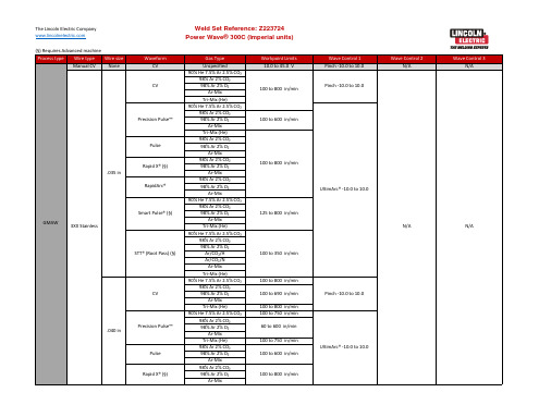
Ar-Mix Tri-Mix (He) 90% He 7.5% Ar 2.5% CO₂ 98% Ar 2% CO₂ 98% Ar 2% O₂
100 to 625 in/min
75 to 500 in/min
75 to 495 in/min
75 to 780 in/min
75 to 760 in/min
100 to 510 in/min
90 to 225 in/min
Wave Control 1 Pinch -10.0 to 10.0 UltimArc® -10.0 to 10.0 Pinch -10.0 to 10.0 UltimArc® -10.0 to 10.0 UltimArc® -10.0 to 10.0 Pinch -10.0 to 10.0 UltimArc® -10.0 to 10.0 Pinch -10.0 to 10.0 UltimArc® -10.0 to 10.0 Pinch -10.0 to 10.0 UltimArc® -10.0 to 10.0 UltimArc® -10.0 to 10.0
100 to 600 in/min
100 to 645 in/min 100 to 625 in/min 100 to 645 in/min 90 to 250 in/min 125 to 700 in/min 150 to 750 in/min 125 to 800 in/min
Wave Control 1 UltimArc® -10.0 to 10.0
- 1、下载文档前请自行甄别文档内容的完整性,平台不提供额外的编辑、内容补充、找答案等附加服务。
- 2、"仅部分预览"的文档,不可在线预览部分如存在完整性等问题,可反馈申请退款(可完整预览的文档不适用该条件!)。
- 3、如文档侵犯您的权益,请联系客服反馈,我们会尽快为您处理(人工客服工作时间:9:00-18:30)。
Sub arc Cell Config
Sub arc Cell Config(埋弧单元配置)是整套林肯焊机中的配置软件。
将多台焊机的通讯连接好之后,可以通过该软件进行配置,将我们需要用到的焊
机分为一组,同时生成一个配置文件。
该配置文件可在Command Center中被调用,从而达到控制该组焊机的目的。
双击软件图标,出现配置对话框。
对话框上部是所有已通讯的焊机,可以
通过单机点选某台焊机,并点击向下箭头的方式把该焊机选入下部的配置框内。
当把所有需要用到的焊机全部选入配置框内后,点击“NEXT”,之后选择“NO”进入确认界面,选择“OK”后开始生成配置文件,生成结束点击“Finish”进
行确认。
Command Center
Command Center(指令中心)软件是焊接时主要使用的可以设置焊接参数、焊接模式、控制焊接启停及实时监控并记录焊接数据的多功能软件。
通过该软
件可以调用“SubarcCellConfig”中已保存的焊机配置,选择焊接模式,输入
焊接参数来完成对焊接的控制。
双击软件图标进入(如图一)。
如首次使用该软件,则会自动弹出选择焊
机配置的对话框;如非首次使用则直接进入上次关闭时的配置。
如需更改,请
点击“File”(文件)下拉菜单中的“Connect”(连接)选项,在弹出的文件选择对话框中进行选择(如图二)。
图一
图二
选择好焊机配置后,在“Arc Balance”(电弧平衡)中选择所需的焊接模式(如图三)。
“CC”为恒流,可设置焊接电流和电压;“CV”为恒压,可设
置送丝速度和电压。
“DC-”为直流正接,“DC+”为直流反接,“Sine Wave”为交流正弦波,“Square Wave”为交流方波。
若选择交流还可以调整“Offset”(偏移)和“Balance”(占空比)。
偏移设置的范围为-25%~25%,数值越小熔深越小,熔敷率越高;占空比设置的范围为25%~75%,数值越小熔深越小,熔
敷率越高,搅动效果越低。
图三
选择好所需的焊接模式后,在“Set Point”(设定值)中输入所需的焊接参数(如图四),包括Strike引弧,Start启弧,Upslope爬坡,Welding焊接,Down-slope下坡,Crater填坑,Burnback回烧,Restrike重新引弧8种
状态,其中建议Strike,Welding,Crater,Burnback,Restrike赋予设定数值,其他状态可根据具体情况选择是否设定数值。
在设定好焊接模式和焊接参数后,在“File”中选择“Save machine setting”通过生成设备设置来保存该设置,便于以后调用。
若需调用已有的设备设置,则可直接点击“Restore machine settings”,在弹出的文件路径选择对话框中选择。
图四
软件中的“Charts”(图表)为焊接时电流,电压,送丝速度的实时监控
曲线画面,通过该画面可以有效的观察整个焊接过程中各参数是否出现过大的
起伏,从而检测焊接电弧是否稳定。
“System Status”(系统状态)可以显示焊机状态,确认焊机是否准备就绪;当出现问题时,可以显示出现问题的原因。
软件“File”(文件)选项下拉菜单中的“Preferences”(偏好设置)中可更改多种个性化设置。
分为一般设置,数据日志,杂项设置,如图五、图六、图七所示。
需要注意的是一般设置中,如选择被动模式,即整个软件仅作为监
控软件而无法进行焊接控制,无法启停焊接,也无法更改数据。
图五
图六 图七。