林肯焊机PowerWaveACDC1000操作手册中文版
林肯焊机说明书
林肯焊机说明书Ⅰ.机械安装1.机头安装安装应牢固以防起弧时机头移动,注意机头与工作电缆应与地绝缘。
根据需要,可装在垂直调节器/水平调节器/行走小车上,所定的机头出厂前根据用户的订购模式安装送丝比率,当改变焊丝直径时需改变送丝轮和导向管。
对不同直径的焊丝需调节随动轮压力调节螺丝,焊丝分两档0.9-2.4mm和3.0-5.6mm。
根据需要调节,对较软的焊丝,压力宜小一点。
出厂时送丝轮设为正转(如图所示方向),但安装板可转动180º,并对换校直器和导电杆,送丝轮转动方向通过改变控制箱内接线上626,627号线来实现。
一般用25kg送丝盘。
NA-3S/NA-4/NA-3SF出厂时所装焊丝校直器的焊丝直径大于2mm以上。
机头安装好后,通过校直器和送丝导向管安装焊丝(其入口处为倒圆)而出丝导向管入口处为倒角)。
2.控制箱安装控制箱在标准行走小车或其它的机架上,当装在其它机架上时,打开控制箱后盖,按照控制箱底板上的安装孔固定控制箱。
3.导电杆组件国内一般常用K231 和K226●K231 导电杆组件:一般用于600A,更高电流可能引起导电嘴磨损坏。
适用于Ф2.4-5.6mm,对不同焊丝需不同导电嘴。
对Ф2.0-2.4mm焊丝还需导电嘴选配件和导丝管。
把工件电缆控制接到导电杆上,用螺栓拧紧,不用完全校直焊丝,以保持良好的电接触。
把焊剂漏斗的软管接到锥形组件的开口处。
要注意经常更换坏的导电嘴。
●K226 压钳式导电杆:一般用于600-1000A。
K226-T 由两个锥形夹组成用于Ф2.4-3.2mm。
K226R由一个锥形夹和一个方形夹组成,用于Ф3.2-5.6mm。
导电杆装在机头的下部,注意锥形夹的斜坡应朝向工件移动方向。
压钳应与导向管对直,通过调节夹钳一侧的螺丝来调节。
Ⅱ.电气安装1.电缆连接需600W,115V/50AC(其中,350W 给送丝电机和控制电路,250W 给行走电路)●从机头到控制箱:所有的工件电缆都接到控制箱后部,每个机头都带1.2m 长电机电缆和1.2m 长焊剂斗电缆,插到控制箱一侧对应的接口内。
林肯DC1000-NA5自动埋弧焊机维修经验

林肯DC1000/NA5自动埋弧焊机维修经验
本内容介绍了林肯埋弧焊机的维修经验,这种机器在国内埋弧自动生产线用的非常多,焊接性能和焊接质量都很好,最重要的是质量可靠,经久耐用。
但并不代表永远不会坏。
由于是进口机,坏了维修会比较麻烦,一般控制板坏了林肯公司以及经销商都不会进行维修,只是更换新板。
而且控制板的价格都不菲,少则几千,贵的几万。
为了减少客户的维修成本,小弟对林肯一系列的进口和国产焊机整机电路以及控制板工作原理进行了一些研究,学习到一点皮毛,这回正好运用这点皮毛技术为客户解决一点难题,为客户节约了维修成本,最大限度缩短了设备停工时间,将机器故障带来的损失减少到了最少。
好了废话不多说,来看看林肯机器到底是怎幺修的,有图有真相哦。
两台排排坐的林肯DC1000埋弧焊主机。
林肯电子Power Wave S350进阶过程焊接器说明书

WHAT’S INCLUDEDK2823-3 Base Unit Includes:10 ft. (3.0 m) input power cordRECOMMENDED WIRE FEEDERSPower Feed 84 Bench andPower Feed 25MTHE LINCOLN ELECTRIC COMPANY22801 St. Clair Avenue • Cleveland, OH • 44117-1199 • U.S.A.PH: 216-481-8100 • © Lincoln Global, Inc. All Rights Reserved.All trademarks and registered trademarks are the property of their respective owners.ADVANCED PROCESS WELDERSProcessesStick, DC TIG, Pulsed DC TIG, MIG, Pulsed MIG, Flux-CoredProduct NumberK2823-3 Power Wave® S350K3005-3 Power Wave S350 Ready-Pak® (Steel) See back for complete specsInput Voltage208/230/380-415/460/575/1/3/50/60Input Current @ Rated Output3 Ph / 40% Duty Cycle: 39/35/19/17/14A1 Ph / 40% Duty Cycle: 60/61/NA/NA/NA AOutput Range5-350 AmpsRated OutputGMAW: 350A/31.5V/40%GMAW: 300A/29V/100%Weight/Dimensions (H x W x D)85 lbs. (38.6 kg)20.40 x 14 x 24.80 in.(518 x 356 x 630 mm)INPUT OUTPUT/greenWAVEFORM CONTROL TECHNOLOGY®PROCESS CAPABILITIESPulse-on-Pulse®(with STT® Module)Upgradeable for additional processesto be developed in the future.LI NC OL N E L E C TR ICTwo Year ExtendedWarranty available inthe U.S.A. and Canada.Shown: K2823-3Power Wave S350[ 2 ] | Power Wave S350To tap into the Power Wave S350 Stick, TIG and CV MIG process capability withouta Power Feed ® series wire feeder, add the K3001-2 S-Series User Interface Kit. This optional interface provides full control of welding parameters from the front panel of the power source for Stick and TIG processes.When used with a Power Feed series wire feeder, the feeder is typically used forcontrolling the system and the K3001-2 S-Series User Interface Kit meters can be used for viewing amps and volts. Kit also includes 12-pin Universal Remote Receptacle and TIG Gas Solenoid.FRONT1. Optional S-Series User Interface (K3001-2) for Stick,TIG and CV MIG with voltage sensing feeder 2. Status Light 3.Thermal Fault Indicator Light4. Tweco ®-Style Cam-Lock Output Terminals5. Optional Output Control Receptacle – 12-pin (included with K3001-2 S-Series User Interface)6. Work Sense Lead Receptacle7. Main Power Switch8.Reversible HandlesBACK9. 115V (10 Amp) AC Duplex Auxiliary Power Receptacle and Circuit Breaker(Optional - Order K2829-1 Kit)10. Arc L ink ® Welding System Component Communication Cable Receptacle 11. Circuit Breaker12. Sync Tandem/STT ® Receptacle 13. Input Power Cable Connection 14. TIG Solenoid Kit Knockout (optional TIG Solenoid included with K3001-2 S-Series User Interface) 15. Ethernet Cable Receptacle 16.Reversible Handles1234567910111213141516• Volts/Amps Control – Adjust volts in MIG and Flux-Cored welding or adjust amperage in Stick or TIG welding.• Welding Mode – Select the stick, TIG or CV wire process.• Advanced Process Options – Control pre- and post-weld settings to optimize arc starts and stops.• Arc Control – Adjust arc characteristics to match individual preferences.Reversible handles shownThe S-Series User Interface Kit allows control over:GENERAL OPTIONSWireless Connectivity Module Simple and secure machineconnectivity solution for monitoring and control capabilities without the hassle of costly network cables. Order K4352-1S-Series User Interface Kit This kit allows local control of stick, TIG and wire processes from the power source control panel. Includes TIG Solenoid and Remote Control Connector. Order K3001-2115V Auxiliary KitAdd a duplex 115V receptacle to the back of the machine. Includes PC board and harness which must be installed. Order K2829-1Inverter and Wire Feeder Cart Rear-wheeled cart with frontcasters and gas bottle platform. Convenient handles allow for easy cable storage. Small footprint fits through 30 in. (762 mm) door. Not intended for use with double head wire feeders. Order K3059-4Dual Cylinder Inverter & Wire Feeder CartRear-wheeled cart with frontcasters and dual cylinder platform. Convenient handles allow for easy cable storage. Small footprint fits through 30 inch (762 mm) door. Order K3059-5Tweco Style Cam-Lock Adapter Plug for Work & Electrode CablesCable plug for 2/0 (50 mm 2) cable. Order K2946-1Work Voltage Sense Lead Kit Required to accurately monitor voltage at the arc.Order K940-25 for 25 ft. (7.6 m) Order K1811-50 for 50 ft. (15.2 m)Order K1811-100 for 100 ft. 30.5 m)LC-40Tweco-Style Plug (male, 1/0 Thru 2/0) Order K3416-70LC-40Tweco-Style Receptacle (female, 1/0 Thru 2/0) Order K3417-70LC-40HDTweco-Style Plug (male, 3/0 Thru 4/0) Order K3416-90LC-40HDTweco-Style Receptacle (female, 3/0 Thru 4/0) Order K3417-90Deluxe Adjustable Gas Regulator & Hose KitAccommodates CO 2, Argon, or Argon-blend gas cylinders. Includes a cylinder pressure gauge, dual scale flow gauge and 4.3 ft.(1.3 m) gas hose. Order K586-1Power Wave S350 | [ 3 ]Power Wave S350 Ready-Pak (for Steel)• P ower Wave S350 Power Source (K2823-3)• P ower Feed 84 Wire Feeder (Bench Model) (K3328-13)• .035 in. (0.9 mm) Drive Roll and Split Wire Guide Kit (KP1505-035S)•M agnum ® PRO Curve ™ 400 Gun and Cable Package (K2952-2-10-45)• W ork Lead and Wire Feeder Power Source Cables Package – 350 amps, 60% duty cycle with Tweco style Cam-Lock connectors and Ground Clamp (K1803-2)• I nverter and Wire Feeder Cart (K3059-4)Ready-Pak PackagesReady-Pak packages are assembled and shipped on one pallet. Welding wire and shielding gas must be ordered separately.maintaining a high power factor and efficiency.generation. It also features 100Mbps Full Duplex Ethernet to support Lincoln Electric’s CheckPoint.Rugged ReliabilityTested under severe conditions:• Extreme Temperature Ranges • Extreme Humidity • Rain• Dirt and Dust• IP23 Rated PerformanceCheckPointCheckPoint, cloud server-based and mobile delivery solutions, is the welding industry’s most advanced weld data collection and monitoring tool, allowing fabricators to analyze their welding operations and processes. These tools can provide necessary data for customer ISO, Six Sigma, statistical process control (SPC), quality cost delivery (QCD), overall equipment effectiveness (OEE) and lean manufacturing efforts. CheckPoint is offered at no charge with every Power Wave purchase.RECOMMENDED ACCESSORIESShown:K1811-100General Options Continued Cool Arc 55 Water CoolerDesigned to integrate with Power Wave S350 and S500 power sources to cool water-cooled welding guns or torches rated up to 500 amps. Recommended for and hand-held MIG, TIG and Plasma cutting operations. 115V/1/60. The 55 S model includes an ArcLink communication flow sensor that detects water flow to prohibit welding when no flow is present. Order K3086-1 for Cool Arc 55 Order K3086-2 for Cool Arc 55 S STICK OPTIONSAccessory KitComplete kit for stick welding. Includes 30 ft. (9.1 m) electrode cable, 25 ft. (7.6 m) work cable, headshield, work clamp and electrode holder.Order K875 for 150 amps Remote Output Control with 12-pin Universal Connector Permits remote adjustment of output. Requires K3001-1 Stick/TIG User Interface.Order K857-2 for 25 ft. (7.6 m)12-pin to 6-pin AdapterAllows older 6-pin remote controls (K870, K963-3, K857) to be used with 12-pin Universal Connection. Order K2909-1TIG OPTIONS PTA-26FV 200 Amp Air-Cooled TIG Torch Order K1783-11 for 12.5 ft. (3.8 m) length, 1-cable. With Tweco-style adapter.Foot Amptrol ™ with12-pin Universal Connector Provides 25 ft. (7.6 m) of remote current control for TIG welding. Requires K3001-2 S-Series User Interface Kit. Order K870-2Parts KitsMagnum Parts Kits provide all the torch accessories you need to start welding. Parts kits provide collets, collet bodies, a back cap, alumina nozzles and tungstens in a variety of sizes, all packaged in an easy to carry reclosable box. Order KP508 for PTA-17 Order KP509 for PTA-26Hand Amptrol ™ with12-pin Universal Connector Provides 25 ft. (7.6 m) of remote current control for TIG welding. Requires K3001-2 S-Series User Interface Kit. Order K963-4Tweco Style TIG Torch Adapter Allows a one-cable TIG Torch to connect to the machine’s Tweco style output terminal. Order K960-3WIRE FEEDER OPTIONS Work and Wire Feeder 2/0 Weld PackageIncludes Tweco-style Cam-Lock connectors, work clamps, 15 ft. (4.5 m) work cable and 10 ft. (3.0 m) electrode cable. Rated 350 amps, 60% duty cycle. Order K1803-2Magnum PRO AL Air-Cooled & Water-Cooled Push-Pull Guns The Magnum PRO AL gooseneck style guns are designed to optimize a push-pull welding operation for aluminum. Uses Magnum PRO MIG Gun expendables. Available in 7-pin and 12-pin connections. Request Publication E12.14Power Wave STT Module This module allows easy connection and fast digitalcommunication with compatible Power Wave S-Series powersources, Power Feed wire feeders, and compatible water coolers. Add STT capability without having to purchase a second power source.Order K2902-1 US/Int’l (shown) Order K2921-1 CEPower Wave Advanced Module Provides multi-process reverse polarity (DC+), straight polarity (DC-), AC, high frequency TIG and STT functionality. Compatible with Power Wave S350 and S500.Order K2912-1C U S T O M E R A S S I S T A N C E P O L I C YThe business of The Lincoln Electric Company is manufacturing and selling high quality welding equipment, consumables, and cutting equipment. Our challenge is to meet the needs of our customers and to exceed their expectations. On occasion, purchasers may ask Lincoln Electric for information or advice about their use of our products. Our employees respond to inquiries to the best of their ability based on information provided to them by the customers and the knowledge they may have concerning the application. Our employees, however, are not in a position to verify the information provided or to evaluate the engineering requirements for the particular weldment. Accordingly, Lincoln Electric does not warrant or guarantee or assume any liability with respect to such information or advice. Moreover, the provision of such information or advice does not create, expand, or alter any warranty on our products. Any express or implied warranty that might arise from the information or advice, including any implied warranty of merchantability or any warranty of fitness for any customers’ particular purpose is specifically disclaimed.Lincoln Electric is a responsive manufacturer, but the selection and use of specific products sold by Lincoln Electric is solely within the control of, and remains the sole responsibility of the customer. Many variables beyond the control of Lincoln Electric affect the results obtained in applying these types of fabrication methods and service requirements. Subject to Change – This information is accurate to the best of our knowledge at the time of printing. Please refer to for any updated information.(1) Based on the U.S. National Electrical Code(2)On 230 Volt / 1 Phase inputs, the peak rating is at a duty cycle of 30%, except for GTAW processes (3)On 208 Volt inputs, the maximum output is limited to 300 ampsFor best welding results with Lincoln Electric equipment, always use Lincoln Electric consumables. Visit for more details.Shown: Cool Arc 55 S。
林肯电焊机操作手册说明书

SP-100OPERA TOR'S MANUALFor use with machines having Code Number 9284 and above .Sales and Service through Subsidiaries and Distributors WorldwideWorld's Leader in Welding and Cutting Products Premier Manufacturer of Industrial MotorsIM366-BNovember 1993Safety Depends on YouLincoln arc welding equipment is designed and built wit h safet y in mind. However, your overall safety can be increased by proper instal-lat ion ... and t hought ful operat ion on your part.DO NOT INSTALL OPERATE OR REPAIR THIS EQUIPMENT WITHOUT READ-ING THIS MANUAL AND THE SAFETY PRECAUTIONS CON-TAINED THROUGHOUT.And,most importantly, think before you act and be careful.9284; 9429; 9521; 9522; 9725;9726; 9794; 9795; 10050Thank Youfor selecting a QUALITY product by Lincoln Electric.We want you to take pride in operating this Lincoln Electric C ompany product ••• as much pride as we have in bringing this product to you!Read this Operators Manual completely before attempting to use this equipment. Save this manual and keep it handy for quick reference. Pay particular attention to the safety instructions we have provided for your protection. The level of seriousness to be applied to each is explained below:PRODUCT DESCRIPTIONThe SP-100, Type K462, is a complete semiautomatic constant voltage DC arc welding machine. Included is a solid state controlled, single phase constant voltage transformer/ rectifier power source and a wire feeder for feeding .023 – .030" (0.6 – 0.8 mm) solid steel electrode and .035" (0.9 mm) cored electrode.The SP-100 is ideally suited for individuals having access to 115 volt AC input power, and wanting the ease of use, quality and dependability of both gas metal arc welding or GMAW (also known as MIG welding) and the Innershield®electrode process (self-shielded flux-cored or FC AW). A convenient chart is mounted inside the wire feed section door for setting welding procedures for 24 gauge through 12 gauge (0.6 – 2.5 mm) mild steel (Chart also may be found in this manual). The SP-100 is a rugged and reliable machine that has been designed for dependable ser-vice and long life.RECOMMENDED PROCESSES AND EQUIPMENTThe SP-100 can be used for welding mild steel using the GMAW, single pass, process which requires a supply of shielding gas or it can be used for the self-shielded, Innershield electrode process.The recommended gas and electrode for GMAW is welding grade CO2gas and .025" (0.6 mm) diameter Lincoln L-56 mild-steel welding wire [supplied on 12 1/2 lb (6 kg) spools]. For 14 gauge (2.0 mm) and thin-ner, CO2gas is recommended because it gives equal or better performance than a blended gas at a lower cost. A mixed gas consisting of 75 to 80% Argon and 20 to 25% CO2is recommended for welding on heav-ier gauge [12 gauge (2.5 mm) for example] steel.The recommended electrode for the self-shielded process is .035" (0.9 mm) diameter Lincoln Innershield NR-211-MP on 10 lb (4.5 kg) spools. This electrode can be used for all position welding of 20 gauge through 5/16" (1.0 – 8.0 mm) thick steel [multi-ple passes are required for 1/4" and 5/16" (6.0 and 8.0 mm)].OPTIONAL ACCESSORIES1.K463 CO2G as Regulator and Hose Kit—Includes a preset, nonadjustable pressure and flow regulator for use on C O2cylinders. Also included is a 10 foot (3.0 m) gas hose which con-nects to the rear of the SP-100.2.K499 Ar-Mixed Gas Regulator and Hose Kit—Includes a preset, nonadjustable pressure and flow regulator for use on argon-mixed gas cylin-ders. Also included is a 10 foot (3.0 m) gas hose which connects to the rear of the SP-100.3..035 (0.9 mm) Innershield®Welding Kit —Includes a contact tip, a gasless nozzle and a cable liner to permit the SP-100 gun and cable to use a .035" (0.9 mm) diameter flux-cored elec-trode. Also included is a spool of .035 (0.9 mm) Innershield®NR-211-MP.Two kits are available:K549-1 kit is for use with the Magnum™100L gun (with red trigger).K464 kit is for use with the original Lincoln Electric®gun (with black trigger).4.M15448-1 Reversible Drive Roll with doubleknurled grooves for .035 cored electrode.5.K467 Input Line Cord — Same as line cord sup-plied with the SP-100 but has a NEMA type 5-20P plug for use on 25 amp branch circuits.To install optional features refer to instructions included with the kit, and/or in this manual.INSTALLATIONDESCRIPTION OF CONTROLSBecome familiar with the SP-100 controls and compo-nents before attempting to weld. Refer to illustrations and lettered items below for brief descriptions.A.Wire speed — Controls the wire speed from 50 –400 in./min (1.3 – 10 m/min). The control can be preset on the dial to the setting specified on the SP-100 Application Chart located on the inside of the wire feed section door. Wire speed is not affected when changes are made in the voltage control. The control is marked (“olo”)B.Power ON/OFF switch — When the power is on,the fan motor will run and air will be exhausted out the louvers in the front of the machine. The welding output and wire feeder remain off until the gun trigger is pressed.C.Voltage control — A continuous control that givesfull range adjustment of power source output volt-age. Can be adjusted while welding.D.Thumbscrew — secures gun and cable assembly.E.Positive (+) and negative (–) output terminals.F.Shielding gas hose (factory installed, not shown)— routed from gas solenoid inside rear of machine to gun connector block.G.Gun trigger lead connectors.H.Circuit breaker — Protects machine from damageif maximum output is exceeded. Button will extend out when tripped. (Manual reset.)I.Wire spool spindle.J.Gas solenoid inlet fitting.K.Power cord.L.Spring loaded pressure arm — adjusts pressureof idle roll on wire.M.Wire feed gearbox and gun connector block.N.Wire feed section door — With application chartfor machine setting procedures.O.Gun cable and control lead access hole.P.Work cable access hole.LOCATIONLocate the welder in a dry location where there is free circulation of clean air into the louvers in the back and out the front. A location that minimizes the amount of smoke and dirt drawn into the rear louvers reduces the chance of dirt accumulation that can block air pas-sages and cause overheating.WORK CABLE AND CLAMP INSTALLATIONWork Clamp InstallationAttach the work clamp to the work cable per the fol-lowing:1.Unplug the machine or turn the power switch to the “Off” position.2.Insert the work cable terminal lug with the larger hole through the strain relief hole in the work clamp as shown below.3.Fasten securely with the bolt and nut provided.Work cableWork clampWork Cable Installation1.Open the wire feed section door on the right side ofthe SP-100.2.Pass the end of the work cable that has the termi-nal lug with the smaller hole through the hole (holeD) next to the louvers in the case front.3.Route the cable under and around the back of thewire feed unit.ing wing nut provided, connect the terminal lugto the negative (–) output terminal located above the wire feed unit; item M (make certain that both wing nuts are tight).NOTE: This connection gives the correct electrode polarity for the GMAW process. If using Innershield, see Output Polarity C onnection Section below for negative electrode polarity connection. OUTPUT POLARITY CONNECTIONThe SP-100, as shipped, is connected for positiveelectrode polarity.To connect for negative electrode polarity (required for the Innershield process), connect the short cable attached to the gun connector block to the negative (–) output terminal and the work cable to the positive (+) terminal using the provided wing nuts (make cer-tain that both wing nuts are tight).GUN INSTALLATIONAs shipped from the factory, the SP-100 gun is ready to feed .023, .024 or .025" (0.6 mm) wire. If .030" (0.8 mm) wire is to be used, install the .030" (0.8 mm) con-tact tip. .023 – .025" contact tip is stenciled .025 and/or 0.6 mm and .030" contact tip is stenciled .030 and/or 0.8 mm. See Maintenance Section for instruc-tions to change contact tip.If .035" (0.9 mm) Innershield flux cored wire is to be used, see Maintenance Section for instructions to change contact tip, cable liner, and gas nozzle.C onnect the gun cable to the SP-100 per the follow-ing:1.Unplug the machine or turn power switch to the off“O” position.2.Pass the insulated terminals of the gun trigger con-trol leads, one at a time, through the rectangular “keyhole” opening (item F) in the case front. The leads are to be routed under the wire feed unit and through the cable hanger on the inner panel.3.Insert the connector on the gun conductor cablethrough the large hole in the SP-100 case front.Make sure the connector is all the way in the metal connector block to obtain proper gas flow. Rotate the connector so control leads are on the underside and tighten the thumbscrew in the connector block.4.Connect the insulated control lead terminals to thetwo insulated 1/4" (6.4 mm) tab connector bushings located above the “Gun Trigger C onnection” decal in the wire feed section. Either lead can go to either connector. Form the leads so that they are as close as possible to the inside panel.WIRE FEED DRIVE ROLLThe SP-100 drive roll has two grooves; one for .023 –.025" (0.6 mm) solid steel electrode and the other for .030" (0.8 mm) solid and .035" (0.9 mm) flux-cored steel electrode. As shipped, the drive roll is installed in the .023/.025" (0.6 mm) position (as indicated by the stenciling on the exposed side of the drive roll).Replace the washer and retaining screw.connectors{Brass connectorIdle roll armRetaining ScrewWELDING WIRE LOADINGThe machine power switch should be turned to the OFF (“O”) position before working inside the wirefeed enclosure.------------------------------------------------------------------------The machine is shipped from the factory ready to feed 8" (200 mm) diameter spools [2.2" (56 mm) max. width]. These spools fit on a 2" (50 mm) diameter spindle that has a built-in, adjustable* friction brake to prevent overrun of the spool and excess slack in theWARNINGK499 Argon-Mixed Gas Regulator and Hose Kit Install the pressure-flow regulator and gauge to a cylinder according to the instructions in Section 1.10.C onnect one end of the 10 foot (3.0 m) hose to the SP-100 gas inlet fitting and the other end to the regu-lator fitting.The K499 argon-mixed gas pressure-flow regulator is preset by the manufacturer to deliver a nominal flow of 30 cubic feet per hour (14 1/min) of argon or argon-mixed gas. This setting cannot be changed..035" (0.9 mm) Innershield Welding KitIncludes a contact tip, gasless nozzle, and a cable liner to permit the SP-100 gun and cable to use .035 (0.9 mm) diameter flux-cored electrode. Also included is a spool of .035 (0.9 mm) Innershield®NR-211-MP. The K549-1 Kit is for use with the Magnum™100L gun (with red trigger). The fitting on the end of the liner is stenciled with the maximum rated wire size (.045"/1.2 mm).The K464 Kit is for use with the earlier “Lincoln Electric®” gun (with black trigger). The end of the brass fitting on the end of the liner for .035 (0.9 mm) wire is color coded green. The .023-.030 (0.6-0.8 mm) factory installed liner is color coded orange.See Maintenance and Troubleshooting Section for instructions on installing liner and contact tip in gun.K467 Input Line CordSame as line cord supplied with the SP-100 but has a NEMA type 5-20P plug for use on a 25 amp branch circuit with a nominal voltage rating of 115 volts to 125 volts, 60 hertz. Install per the following:1.Turn the SP-100 Power Switch to OFF (“O”).2.If connected, remove the line cord plug from powersupply receptacle.3.Remove the two screws that hold the line cordreceptacle in the SP-100 flanged inlet connector and disconnect the line cord from the SP-100.4.C onnect the S18410 input line cord receptacle tothe SP-100 and replace the retaining screws.OPERATING INSTRUCTIONS1.Decrease stickout2.Increase WFS (wire feed speed) (“oIo”)3.Decrease voltage (“V”)4.Increase speed5.Decrease drag angle6.Check for correct gas, if usedIf Arc Blow Occurs (in order of importance) (NOTE: Try different ground connection locations before adjusting procedures)1.Decrease drag angle2.Increase stickout3.Decrease voltage (“V”)4.Decrease WFS (wire feed speed) (“oIo”) andvoltage (“V”)5.Decrease travel speedTo Eliminate Stubbing (in order of importance)1.Increase voltage (“V”)2.Decrease WFS (wire feed speed) (“oIo”)3.Decrease stickout4.Increase drag angleStubbing occurs when the electrode drives through the molten puddle and hits the bottom plate tending to push the gun up.PROPER GUN HANDLINGMost feeding problems are caused by improper han-dling of the gun cable or electrodes.1.Do not kink or pull the gun cable around sharp cor-ners.2.Keep the gun cable straight as practical when weld-ing.3.Do not allow dolly wheels or trucks to run over thecables.4.Keep the cable clean per maintenance instructionsin this Operation Manual.5.Innershield electrode has proper surface lubrica-tion. Use only clean, rust-free electrode.6.Replace the contact tip when it becomes worn orthe end is fused or deformed.Low or no gas flow Cylinder valve closed Open cylinder valveGas flow not set correctly Set proper flow rateCylinder out of gas Get new cylinder of gasLeak in gas line Inspect and replaceClog or Leak in gun Check for obstruction or defective sealsArc unstable Wrong welding polarity Check polarity - Refer to proper sectionErratic or Intermittent Wrong size, worn and/or Replace tip - remove any spatter on end of tip Arc - Poor Starting melted contact tip"Hunting" ArcWorn work cable or poor connections Inspect - repair or replace as necessaryLoose electrode connections Be sure electrode lead is tight, gun cable tight inwire feeder contact block, gun nozzle and guntip tightM 16576S P 100 W I R I N G D I A G R A MNow Available...12th Edition The Procedure Handbook of Arc WeldingWith over 500,000 copies of previous editions publishedsince 1933, the Procedure Handbook is considered by many tobe the “Bible” of the arc welding industry.This printing will go fast so don’t delay. Place yourorder now using the coupon below.The hardbound book contains over 750 pages of weldinginformation, techniques and procedures. Much of this materialhas never been included in any other book.A must for all welders, supervisors, engineers anddesigners. Many welding instructors will want to use the bookas a reference for all students by taking advantage of the lowquantity discount prices which include shipping by4th class parcel post.$15.00postage paid U.S.A. Mainland How To Read Shop Drawings The book contains the latest information and application data on the American Welding Society Standard Welding Symbols. Detailed discussion tells how engineers and draftsmen use the “short-cut” language of symbols to pass on assembly and welding information to shop personnel.Practical exercises and examples develop the reader’s abilityto visualize mechanically drawn objects as they will appearin their assembled form.187 pages with more than 100 illustrations. Size 8-1/2” x 11”Durable, cloth-covered board binding.$4.50postage paid U.S.A. Mainland New Lessons in Arc Welding Lessons, simply written, cover manipulatory techniques;machine and electrode characteristics; related subjects,such as distortion; and supplemental information on arc welding applications, speeds and costs. Practice materials,exercises, questions and answers are suggested for each lesson.528 pages, well illustrated, 6” x 9” size, bound in simulated,gold embossed leather.$5.00postage paid U.S.A. Mainland Need Welding Training?The Lincoln Electric Company operates the oldest andmost respected Arc Welding School in the United States at itscorporate headquarters in Cleveland, Ohio. Over 100,000stu-dents have graduated. Tuition is low and the training is“hands on”For details write: Lincoln Welding School 22801 St. Clair Ave.Cleveland, Ohio 44117-1199.and ask for bulletin ED-80 or call 216-383-2259 and ask for the Welding School Registrar.Lincoln Welding School BASIC COURSE$700.005 weeks of fundamentals There is a 10%discount on all orders of $50.00 or more for shipment at one time to one location.Orders of $50 or less before discount or orders outside of North America must be prepaid with charge, check or money order in U.S. Funds Only.Prices include shipment by 4th Class Book Rate for U.S.A. Mainland Only.Please allow up to 4 weeks for delivery.UPS Shipping for North America Only.All prepaid orders that request UPS shipment please add:$5.00For order value up to $49.99$10.00For order value between $50.00 & $99.99$15.00For order value between $100.00 & $149.00For North America invoiced orders over $50.00 & credit card orders, if UPS is requested, it will be invoiced or charged to you at cost.Outside U.S.A. Mainland order must be prepaid in U.S. Funds. Please add $2.00 per book for surface mail or $15.00 per book for air parcel post shipment.METHOD OF PAYMENT:(Sorry, No C.O.D. Orders)CHECK ONE:Name:_______________________________________________Please Invoice (only if order is over $50.00)Address:_______________________________________________Check or Money Order Enclosed, U.S. Funds only_______________________________________________Credit Card - Telephone:_______________________________________________Signature as it appears on Charge Card:Account No.Exp Date |_|_||_|_|______________________Month Year USE THIS FORM TO ORDER:Order from:BOOK DIVISION, The Lincoln Electric Company, 22801 St. Clair Avenue, Cleveland, Ohio 44117-1199BOOKS OR FREE INFORMATIVE CATALOGSTelephone: 216-383-2211 or, for fastest service, FAX this completed form to: 216-361-5901.Lincoln Welding School Titles:Price Code Quantity Cost (ED-80)New Lessons in Arc Welding $5.00L Seminar Information Procedure Handbook “Twelfth Edition”$15.00PH (ED-45)How to Read Shop Drawings $4.50H Educational Video Information Incentive Management $5.00IM (ED-93)A New Approach to Industrial Economics $5.00NA James F. Lincoln Arc WeldingThe American Century of John C. Lincoln $5.00AC Foundation Book Information Welding Preheat Calculator $3.00WC-8(JFLF-515)Pipe Welding Charts $4.50ED-89SUB TOTALAdditional Shipping Costs if anyTOTAL COSTJapaneseChineseKoreanArabicREAD AND UNDERSTAND THE MANUFACTURER’S INSTRUCTION FOR THIS EQUIPMENT AND THE CONSUMABLES TO BE USED AND FOLLOW YOUR EMPLOYER’S SAFETY PRACTICES.SE RECOMIENDA LEER Y ENTENDER LAS INSTRUCCIONES DEL FABRICANTE PARA EL USO DE ESTE EQUIPO Y LOS CONSUMIBLES QUE VA A UTILIZAR, SIGA LAS MEDIDAS DE SEGURIDAD DE SU SUPERVISOR.LISEZ ET COMPRENEZ LES INSTRUCTIONS DU FABRICANT EN CE QUI REGARDE CET EQUIPMENT ET LES PRODUITS A ETRE EMPLOYES ET SUIVEZ LES PROCEDURES DE SECURITE DE VOTRE EMPLOYEUR.LESEN SIE UND BEFOLGEN SIE DIE BETRIEBSANLEITUNG DER ANLAGE UND DEN ELEKTRODENEINSATZ DES HER-STELLERS. DIE UNFALLVERHÜTUNGSVORSCHRIFTEN DES ARBEITGEBERS SIND EBENFALLS ZU BEACHTEN.JapaneseChineseKoreanArabicLEIA E COMPREENDA AS INSTRUÇÕES DO FABRICANTE PARA ESTE EQUIPAMENTO E AS PARTES DE USO, E SIGA AS PRÁTICAS DE SEGURANÇA DO EMPREGADOR.(such as loss of business, etc.) caused by the defect or Sales and Service through Subsidiaries and Distributors Worldwide22801 St. Clair Ave. Cleveland, Ohio 44117-1199 U.S.A. Tel. (216) 481-8100Premier Manufacturer of Industrial Motorsd。
林肯电力(Lincoln Electric)生产的焊接和切割设备操作手册说明书

RANGER ™3 PHASEOPERATOR’S MANUALFor Machines with Code Number 11079IM831October, 2004Safety Depends on YouLincol n arc wel ding and cutting equipment is designed and buil t with safety in mind. However, your overall safety can be increased by proper installation ... and thought-ful operation on your part.DO NOT INSTALL, OPERATE OR REPAIR THIS EQUIPMENT WITHOUT READING THIS MANUAL AND THE SAFETY PRECAUTIONS CONTAINED THROUGHOUT.And, most importantl y, think before you act and be careful.Copyright © 2004 Lincoln Global Inc.This manual covers equipment which is nolonger in production by The Lincoln Electric Co. Speci cations and availability of optional features may have changed.Mar ‘95Mar. ‘93vvfor selecting a QUALITY product by Lincoln Electric. We want you to take pride in operating this Lincoln Electric Company product ••• as much pride as we have in bringing this product to you!1. Output rating in watts is equivalent to volt - amperes at unity factor.Output voltage is within +/-10% at all loads up to rated capacity.When welding available auxiliary power will be reduced.Internal combustion engines are designed to run in a level condition which is where the optimum perfor-mance is achieved. The maximum angle of operation for the engine is 15 degrees from horizontal in any direction. If the engine is to be operated at an angle,provisions must be made for checking and maintain-ing the oil at the normal (F ULL) oil capacity in the crankcase in a level condition.When operating at an angle, the effective fuel capaci-ty will be slightly less than the specified 9 gallons (34Liters).LIFTINGThe RANGER 3 PHASE weighs approximately 575lbs.(261kg) with a full tank of gasoline. A lift bail is mounted to the machine and should always be used when lifting the machine.HIGH ALTITUDE OPERATIONIf the RANGER 3 PHASE will be consistently operat-ed at altitudes above 5000 ft(1524m), a carburetor jet designed for high altitudes should be installed. This will result in better fuel economy, cleaner exhaust,and longer spark plug life. It will not give increased power which is decreased at higher altitudes. Engine horsepower is reduced by 3.5% per 1000feet(304.8m) for altitudes above 377 feet(115m).Do not operate a RANGER 3 PH ASE with a highaltitude jet installed at altitudes below 5000ft.(1524m) This will result in the engine runningtoo lean and result in higher engine operatingtemperatures which can shorten engine life.-----------------------------------------------------------------------Contact your local Kohler Authorized Dealer for highaltitude jet kits that are available from the engine •Shut off welder and allow muffler to cool beforetouching muffler.------------------------------------------------------------------------The RANGER 3 PHASE is shipped with the exhaust coming out on the left side. The exhaust can be changed to the opposite side by removing the two screws that hold the exhaust port cover in place and installing the cover on the opposite side. (Operating the RANGER 3 PHASE without the cover in place will result in a higher noise level and no increase in machine output.)LOCATION / VENTILATIONThe welder should be located to provide an unrestrict-ed flow of clean, cool air to the cooling air inlets and to avoid heated air coming out of the welder recirculating back to the cooling air inlet. Also, locate the welder so that engine exhaust fumes are properly vented to an outside area.STACKINGRANGER 3 PHASE machines cannot be stacked.CONNECTION OF LINCOLN ELECTRIC WIRE FEEDERSShut off welder before making any electrical connections.------------------------------------------------------------------------WIRE FEED (CONSTANT VOLTAGE)CONNECTION OF LN-15 ACROSS-THE-ARC WIRE FEEDERThe LN-15 has an internal contactor and the electrode is not energized until the gun trigger is closed. When the gun trigger is closed the wire will begin to feed and the welding process is started.a. Shut the welder off.b. Set the Polarity switch to the desired polarity,either DC (-) or DC (+).c. Attach the single lead from the front of the LN-15to work using the spring clip at the end of the lead.This is a control lead to supply current to the wire feeder motor; it does not carry welding current.d.Set the “RANGE” switch to the “WIRE F EED-CV”position e. Place the Engine switch in the “Auto Idle” position.f. Adjust the wire feed speed at the LN-15 and adjust the welding voltage with the output “CONTROL” at the welder. Output “CONTROL” must be set above 3.Note:LN-15 Control Cable model will not work with• Lift only with equipment of ade-quate lifting capacity.• Be sure machine is stable when lift-ing.• Do not lift this machine using lift bail if it is equipped with a heavy accessory such as trailer or gas cylinder.FALLING• Do not lift machine if lift bail isEQUIPMENT can damaged.cause injury. • Do not operate machine whilesuspended from lift bail.--------------------------------------------------------------------------------CONNECTION OF TH E LN-25 TO TH E RANGER 3PHASE•Shut the welder off.•Connect the electrode cable from the LN-25 to the “ELECTRODE” terminal of the welder.Connect the work cable to the “TO WORK” termi-nal of the welder.•Position the welder “Polarity” switch to thedesired polarity, either DC (-) or DC (+).•Position the “RANGE” switch to the “WIREFEED” position.•Attach the single lead from the LN-25 control boxto the work using the spring clip on the end of the lead - it carries no welding current.•Place the engine switch in the “AUTO” position.•Adjust wire feed speed at the LN-25 and adjustthe welding voltage with the output “CONTROL”at the welder.NOTE:The welding electrode is energized at all times, unless an LN-25 with built-in contactor is used.If the output “CONTROL” is set below “3”, the LN-25contactor may not pull in.CONNECTION OF K930-2 TIG MODULE TO TH E RANGER 3 PHASE.The TIG Module is an accessory that provides high frequency and shielding gas control for AC and DC GTAW (TIG) welding. See IM528 supplied with the TIG Module for installation instructions.Note: The TIG Module does not require the use of a high frequency bypass capacitor. However, if the RANGER 3 PHASE is used with any other high fre-quency equipment, the bypass capacitor must be installed, order kit T12246.INSTRUCTIONSADDITIONAL SAFETY PRECAUTIONSAlways operate the welder with the roof and case sides in place as this provides maximum protection from moving parts and assures proper cooling air flow.Read and understand all Safety Precautions before operating this machine. Always follow these and any other safety procedures included in this manual and in the Engine Owner’s Manual.WELDER OPERATIONWELDER OUTPUT• Maximum Open Circuit Voltage at 3700 RPM is 80 Volts RMS.*Current Sensing for Automatic Idle.(Receptacle viewed from front of Machine)(FOR ALL SINGLE AND ZTHREE PHASE LOADS)TABLE lllELECTRICAL DEVICE USE WITH THE RANGER 3 PHASE.Type Common Electrical Devices Possible ConcernsResistive Heaters, toasters, incandescent NONElight bulbs, electric range, hotpan, skillet, coffee maker.Capacitive TV sets, radios, microwaves, Voltage spikes or high voltageappliances with electrical control.regulation can cause the capac-itative elements to fail. Surgeprotection, transient protection,and additional loading is recom-mended for 100% fail-safeoperation. DO NOT RUNTHESE DEVICES WITHOUTADDITIONAL RESISTIVE TYPELOADS.Inductive Single-phase induction motors, These devices require largedrills, well pumps, grinders, small current inrush for starting.refrigerators, weed and hedge Some synchronous motors maytrimmers be frequency sensitive to attainmaximum output torque, butthey SHOULD BE SAFE fromany frequency induced failures. Capacitive/Inductive Computers, high resolution TV sets,An inductive type line condition-complicated electrical equipment. er along with transient andsurge protection is required,and liabilities still exist. DONOT USE THESE DEVICESWITH A RANGER 3 PHASE The Lincoln Electric Company is not responsible for any damage to electrical components improperly connect-ed to the RANGER 3 PHASE.1.Install a double pole, double throw switch betweenthe power company meter and the premises dis-connect.Switch rating must be the same or greater than thecustomer’s premises disconnect and service over-current protection.2.Take necessary steps to assure load is limited tothe capacity of the RANGER 3 PHASE by installinga 40 amp 240V double pole circuit breaker.Maximum rated load for the 240V auxiliary is 40amperes. Loading above 40 amperes will reduceoutput voltage below the allowable -10% of ratedvoltage which may damage appliances or othermotor-driven equipment.3.Install a 50 amp 120/240V plug (NEMA type 14-50)to the Double Pole Circuit Breaker using No. 8, 4conductor cable of the desired length. (The 50 amp120/240V plug is available in the optional plug kit.)4.Plug this cable into the 50 amp 120/240V recepta-cle on the RANGER 3 PHASE case front.*Each duplex receptacle is limited to 20 amps.**Not to exceed 40A per 120VAC branch circuit whensplitting the 240 VAC output.***Use of 3-Phase AC poower is not recommendedwhile welding.LOADNATIONAL ELECTRICAL CODE FOR ALTERNATE WIRESIZE RECOMMENDATIONS.SUMMARY OF WELDING PROCESSESThis Troubleshooting Guide is provided to help you locate and repair possible machine malfunctions.Simply follow the three-step procedure listed below.Step 1.LOCATE PROBLEM (SYMPTOM).Look under the column labeled “PROBLEM (SYMP-TOMS)”. This column describes possible symptoms that the machine may exhibit. Find the listing that best describes the symptom that the machine isexhibiting.Step 2.POSSIBLE CAUSE.The second column labeled “POSSIBLE CAUSE ” lists the obvious external possibilities that may contribute to the machine symptom.Step 3.RECOMMENDED COURSE OF ACTIONThis column provides a course of action for the Possible Cause, generally it states to contact your local Lincoln Authorized Field Service Facility.If you do not understand or are unable to perform the Recommended Course of Action safely, contact your local Lincoln Authorized Field Service Facility.HOW TO USE TROUBLESHOOTING GUIDEService and Repair should only be performed by Lincoln Electric Factory Trained Personnel.Unauthorized repairs performed on this equipment may result in danger to the technician and machine operator and will invalidate your factory warranty. For your safety and to avoid Electrical Shock, please observe all safety notes and precautions detailed throughout this manual.__________________________________________________________________________R A N G E R 3 P H A S E/ L N -15A N D L N -25 A C R O S S T H E A R C C O N N E C T I O N D I A G R A MM 20266JapaneseChineseKoreanArabicREAD AND UNDERSTAND THE MANUFACTURER’S INSTRUCTION FOR THIS EQUIPMENT AND THE CONSUMABLES TO BE USED AND FOLLOW YOUR EMPLOYER’S SAFETY PRACTICES.SE RECOMIENDA LEER Y ENTENDER LAS INSTRUCCIONES DEL FABRICANTE PARA EL USO DE ESTE EQUIPO Y LOS CONSUMIBLES QUE VA A UTILIZAR, SIGA LAS MEDIDAS DE SEGURIDAD DE SU SUPERVISOR.LISEZ ET COMPRENEZ LES INSTRUCTIONS DU FABRICANT EN CE QUI REGARDE CET EQUIPMENT ET LES PRODUITS A ETRE EMPLOYES ET SUIVEZ LES PROCEDURES DE SECURITE DE VOTRE EMPLOYEUR.LESEN SIE UND BEFOLGEN SIE DIE BETRIEBSANLEITUNG DER ANLAGE UND DEN ELEKTRODENEINSATZ DES HER-STELLERS. DIE UNFALLVERHÜTUNGSVORSCHRIFTEN DES ARBEITGEBERS SIND EBENFALLS ZU BEACHTEN.JapaneseChineseKoreanArabicLEIA E COMPREENDA AS INSTRUÇÕES DO FABRICANTE PARA ESTE EQUIPAMENTO E AS PARTES DE USO, E SIGA AS PRÁTICAS DE SEGURANÇA DO EMPREGADOR.。
林肯电气Bester热带车道500S电焊机操作指南说明书

IM304109/2016REV03HOT ROD 500S OPERATOR’S MANUALENGLISHLincoln Electric Bester Sp. z o.o.ul. Jana III Sobieskiego 19A, 58-263 Bielawa, Polandwww.lincolnelectric.euDeclaration of conformityLincoln Electric Bester Sp. z o.o.Declares that the welding machine:K14089-2 HOT ROD 500S 220/380/440Vconforms to the following directives:2014/35/EU , 2014/30/EUand has been designed in compliance with thefollowing standards:EN 60974-1:2012; EN 60974-10:201420.04.2016Piotr SpytekOperations DirectorLincoln Electric Bester Sp. z o.o., ul. Jana III Sobieskiego 19A, 58-263 Bielawa, Poland12/0512/05 THANKS! For having chosen the QUALITY of the Lincoln Electric products.∙Please Examine Package and Equipment for Damage. Claims for material damaged in shipment must be notified immediately to the dealer.∙For future reference record in the table below your equipment identification information. Model Name, Code & Serial Number can be found on the machine rating plate.Model Name: ………………………………………………………………………………………………………………………………………….Code & Serial Number: ………………………………………………………………….. …………………………………………………………………..Date & Where Purchased …………………………………………………………………. …………………………………………………………………..ENGLISH INDEXSafety (1)Installation and Operator Instructions (2)Electromagnetic Compatibility (EMC) (6)Technical Specifications (7)WEEE (8)Spare Parts (8)Electrical Schematic (8)Accessories (8)Safety11/04WARNINGThis equipment must be used by qualified personnel. Be sure that all installation, operation, maintenance and repair procedures are performed only by qualified person. Read and understand this manual before operating this equipment. Failure to follow the instructions in this manual could cause serious personal injury, loss of life, or damage to this equipment. Read and understand the following explanations of the warning symbols. Lincoln Electric is not responsible for damages caused by improper installation, improper care or abnormal operation.The manufacturer reserves the right to make changes and/or improvements in design without upgrade at the same time the operator’s manual.Installation and Operator InstructionsRead this entire section before installation or operation of the machine.Location and EnvironmentThe HOT ROD 500S welders can be stacked three high when the following precautions are observed: ∙ Be sure the bottom machine is on a firm, levelsurface suitable for the total weight (610kg) of the stacked machines.∙ Stack the machine with the fronts flush.∙ Be certain the pins on the top font corners of thelower machines fit through the holes in the base rails of the upper machines.This machine will operate in harsh environments. However, it is important that simple preventativemeasures are followed to assure long life and reliable operation:∙ Do not place or operate this machine on a surfacewith an incline greater than 15° from horizontal. ∙ Do not use this machine for pipe thawing.∙ This machine must be located where there is freecirculation of clean air without restrictions for air movement to and from the air vents. Do not cover the machine with paper, cloth or rags when switched on.∙ Dirt and dust that can be drawn into the machineshould be kept to a minimum.∙ This machine has a protection rating of IP23. Keep itdry when possible and do not place it on wet groundor in puddles.∙ Locate the machine away from radio controlledmachinery. Normal operation may adversely affect the operation of nearby radio controlled machinery, which may result in injury or equipment damage. Read the section on electromagnetic compatibility in this manual.∙ Do not operate in areas with an ambient temperaturegreater than 55°C.Duty cycle and OverheatingThe duty cycle of a welding machine is the percentage of time in a 10 minute cycle at which the welder can operate the machine at rated welding current.Example: 60% duty cycle:Welding for 6 minutesBreak for 4 minutesExcessive extension of the duty cycle will cause the thermal protection circuit to activate.The machine is protected from overheating by a temperature sensor.When the machine is overheated the output of themachine will turn "OFF", and the Thermal Indicator Light will turn "ON". When the machine has cooled to a safe temperature the Thermal Indicator Light will go out and the machine may resume normal operation.Minutes or decrease duty cycleInput Supply ConnectionCheck the input voltage, phase, and frequency supplied to this machine before turning it on. Verify theconnection of grounding wires from the machine to the input source. The allowable input voltages are 3x220V 50/60Hz, 3x380V 50/60Hz and 3x440V 50/60Hz(3x440V: factory default). For more information about input supply refer to the technical specification section of this manual and to the rating plate of the machine.If it is necessary to change the input voltage:∙ The input cable must be disconnected from themains supply and the machine switched OFF.Cable length Up to 10 m 10 – 50 m 50 – 75 m Cable size 70 mm 2 95 mm 2120 mm 2control is used to set the level of the increased current and arc start current is made easy. electrode and the workpiece. welding it continues to display the average welding current and voltage for 5 seconds.8. Welding Current Knob Control:Potentiometer used to set the output current on the range 50A - 625A (alsoduring welding).9. Local/Remote Switch: Remote Control Unit K10095-1-15M and K870 can be used with this machine. Itchanges control of the Output Current from themachine Welding Current [8] to the K10095-1-15M or K870 and vice versa.10. Remote Control Connector: If a remotecontrol is used, it will be connected to the remote connector (see "Accessories"chapter).11. Negative Output Terminal: Negative14applicable standards. This connection shall be performed only by a qualified person.Welding SMAW (MMA) ProcessHOT ROD 500S does not include the electrode holder with lead necessary and the work lead for SMAWwelding, but the one can be purchased separately (see "Accessories" chapter).For starting welding process with SMAW process you should:∙ First turn the machine off.∙ Determine the electrode polarity for the electrode tobe used. Consult the electrode data for this information.∙ Depending on the polarity of using electrode,connect the work lead and the electrode holder with lead to output socket [11] or [12] and lock them. See the Table 1.Table 1.Output socketP O L A R I T YD C (+) The electrode holderwith lead to SMAW[12] Work lead [11] D C (-) The electrode holder with lead to SMAW[11] Work lead[12]IOff CONTROL DIALS Hot Start OUTPUT CURRENT CONTROL RANGE SWITCH LOW Output Current Control Dial Range LowHIGH Output Current Control Dial Range HighOUTPUT CURRENT CONTROL "MACHINE-REMOTE" SWITCHRemote Output Current ControlMachine Output Current ControlRATING PLATEThree Phase PowerTransformer RectifierRectifier DC OutputConstant Current Characteristic Shielded Metal Arc Welding Line ConnectionHIGH TEMPERATURE WARNING LIGHTHigh Temperature LimitWARNINGWarning IdentificationGROUNDSignifying the Earth (Ground) ConnectionMaintenanceWARNINGFor any repair operations, modifications ormaintenances, it is recommended to contact the nearest Technical Service Center or Lincoln Electric. Repairs and modifications performed by unauthorized service or personnel will cause, that the manufacturer’s warranty will become null and void.Any noticeable damage should be reported immediately and repaired.Routine maintenance (everyday)∙ Check condition of insulation and connections of thework leads and insulation of power lead. If any insulation damage exists replace the lead immediately.∙ Check the welding gun condition: replace it, ifnecessary.∙ Check condition and operation of the cooling fan.Keep clean its airflow slots.Periodic maintenance (every 200 working hours but at list once every year)Perform the routine maintenance and, in addition: ∙ Keep the machine clean. Using a dry (and lowpressure) airflow, remove the dust from the external case and from the cabinet inside.∙ If it is required, clean and tighten all weld terminals.The frequency of the maintenance operations may vary in accordance with the working environment where the machine is placed.Electromagnetic Compatibility (EMC)11/04 This machine has been designed in accordance with all relevant directives and standards. However, it may still generate electromagnetic disturbances that can affect other systems like telecommunications (telephone, radio, and television) or other safety systems. These disturbances can cause safety problems in the affected systems. Read and understand this section to eliminate or reduce the amount of electromagnetic disturbance generated by this machine.Before installing the machine, the operator must check the work area for any devices that may malfunction because of electromagnetic disturbances. Consider the following.∙Input and output cables, control cables, and telephone cables that are in or adjacent to the work area and the machine.∙Radio and/or television transmitters and receivers. Computers or computer controlled equipment.∙Safety and control equipment for industrial processes. Equipment for calibration and measurement.∙Personal medical devices like pacemakers and hearing aids.∙Check the electromagnetic immunity for equipment operating in or near the work area. The operator must be sure that all equipment in the area is compatible. This may require additional protection measures.∙The dimensions of the work area to consider will depend on the construction of the area and other activities that are taking place.Consider the following guidelines to reduce electromagnetic emissions from the machine.∙Connect the machine to the input supply according to this manual. If disturbances occur if may be necessary to take additional precautions such as filtering the input supply.∙The output cables should be kept as short as possible and should be positioned together. If possible connect the work piece to ground in order to reduce the electromagnetic emissions. The operator must check that connecting the work piece to ground does not cause problems or unsafe operating conditions for personnel and equipment.∙Shielding of cables in the work area can reduce electromagnetic emissions. This may be necessary for special applications.due to conducted as well as radio-frequency disturbances.Technical SpecificationsNAME INDEXHOT ROD 500S K14089-2INPUTInput Voltage U1EMC Group / Class FrequencyHOT ROD220/380/440V / 3~ II / A 50 / 60 Hz 500SInput Power at Rated Cycle InputAmperesI1max cosφHOT ROD43 kVA @ 35 Duty Cycle (40°C) 220V 3~ 114A0,89500S 380V 3~ 65,5A440V 3~ 57ARATED OUTPUTDuty Cycle 40°C / 55°C(based on a 10 min. period)Output Current Output VoltageHOT ROD 35% / 25% 600A 44 V 500S 60% / 35% 500A 40 V100% / 60% 375A 35 VOUTPUT RANGEWelding Current Range Peak Open Circuit VoltageHOT ROD50A - 625A 65,5 V500SRECOMMENDED INPUT CABLE AND FUSE SIZESFuse or Circuit Breaker Size Power Lead220V~ 380V~ 440V~HOT RODD 125 A D 63 A D 63 A 4 Conductor, 16mm2500SDIMENSIONWeight Height Width Length HOT ROD203 kg 795 mm 566 mm 813 mm 500SProtection Rating Operating Humidity(t=20°C)Operating Temperature StorageTemperatureIP23 ≤ 90 % from -10 ºC to +55 ºC from -25 ºC to +55 ºCEnglish 8 English WEEE07/06Spare Parts12/05Part list reading instructions∙ Do not use this part list for a machine if its code number is not listed. Contact the Lincoln Electric Service Department for any code number not listed.∙ Use the illustration of assembly page and the table below to determine where the part is located for your particular code machine.∙ Use only the parts marked "●" in the column under the heading number called for in the assembly page (# indicate a change in this printing).First, read the Part List reading instructions above then refer to the "Spare Part" manual supplied with the machine, which contains a picture-descriptive part number cross-reference).Electrical SchematicRefer to the "Spare Parts" manual supplied with the machine.AccessoriesK10376Adapter M14/DINSe (F) (to connect the welding cables). *E/H-400A-70-5M The electrode holder with lead - 5m.*GRD-600A-95-5M Work Lead with the Work Clamp - 5m.FL060583010 FLAIR 600 Gouging torch with mounted monocable - 2,5m.* N/B-600A-95-5M 5m-extension cable for gouging torch. K14090-1 AV Meter KitK10095-1-15M Hand Amptrol.K870 Foot Amptrol.K1039815m-extension cable for remote ctrl box.* Co-operates with K10376 E n g l i s hDo not dispose of electrical equipment together with normal waste!In observance of European Directive 2012/19/EC on Waste Electrical and Electronic Equipment(WEEE) and its implementation in accordance with national law, electrical equipment that has reached the end of its life must be collected separately and returned to an environmentally compatible recycling facility. As the owner of the equipment, you should get information on approved collection systems from our local representative.By applying this European Directive you will protect the environment and human health!。
林肯电子公司的高压电焊机说明书
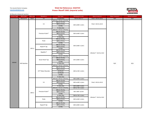
Ar-Mix Tri-Mix (He) 90% He 7.5% Ar 2.5% CO₂ 98% Ar 2% CO₂ 98% Ar 2% O₂
100 to 625 in/min
75 to 500 in/min
75 to 495 in/min
75 to 780 in/min
75 to 760 in/min
100 to 510 in/min
90 to 225 in/min
Wave Control 1 Pinch -10.0 to 10.0 UltimArc® -10.0 to 10.0 Pinch -10.0 to 10.0 UltimArc® -10.0 to 10.0 UltimArc® -10.0 to 10.0 Pinch -10.0 to 10.0 UltimArc® -10.0 to 10.0 Pinch -10.0 to 10.0 UltimArc® -10.0 to 10.0 Pinch -10.0 to 10.0 UltimArc® -10.0 to 10.0 UltimArc® -10.0 to 10.0
100 to 600 in/min
100 to 645 in/min 100 to 625 in/min 100 to 645 in/min 90 to 250 in/min 125 to 700 in/min 150 to 750 in/min 125 to 800 in/min
Wave Control 1 UltimArc® -10.0 to 10.0
林肯焊机Power Wave ACDC 1000操作手册(中文版)
2.PF10A各项焊接参数的设置
2.6 起弧、收弧设置-Arc delay time 默认情况下,按一下按钮2,则指示灯start option亮,此时,显示屏上显示Arc delay time,拨动旋钮1可进行延迟时间的设置(0-5s),OFF表示0S。
2.PF10A各项焊接参数的设置
2.6 起弧、收弧设置-Arc strike 设定好ARC DELAY TIME 后再按一下按钮2,指示灯start option及WFS闪烁,显示 屏1上显示Arc strike,此时可拨动旋钮2进行起弧时送丝速度设置(10-200)
2.PF10A各项焊接参数的设置
2.6 起弧、收弧设置-crater time填弧坑时间 Start time设置完成后,再按一下按钮2,显示屏上显示crater time, 旋转旋钮1进行 熄弧时间设置(0-10s),OFF表示熄弧时间为0s,该设置不为0时,可拨动旋 钮2和旋钮3分别进行收弧电流及电压的调节
5.2.4按住储存按钮组的一号按钮2-5秒,将数据保存。
5.焊接实例 5.3.调整埋弧焊机头的角度和位置 焊丝干伸长32mm 焊枪角度0-3° 推角焊枪与底板的夹角:40°
5.4.设定焊接速度为22-23 Inch/min.
5.5.按下启动按钮开始焊接。
5.6.按下停止按钮停止焊接.
2.PF10A各项焊接参数的设置
2.6 起弧、收弧设置-burn back焊丝回烧时间 Crater time设置完成后,再按一次按钮2,可在0-2s间进行Burn back设置,再按 一下按钮2,则start option灯亮,显示屏上显示为arc delay time,回到默认状态。
3.焊接操作介绍
4.与设备相关的焊接资料
- 1、下载文档前请自行甄别文档内容的完整性,平台不提供额外的编辑、内容补充、找答案等附加服务。
- 2、"仅部分预览"的文档,不可在线预览部分如存在完整性等问题,可反馈申请退款(可完整预览的文档不适用该条件!)。
- 3、如文档侵犯您的权益,请联系客服反馈,我们会尽快为您处理(人工客服工作时间:9:00-18:30)。
2.PF10A各项焊接参数的设置
2.3焊接电流、送丝速度设置 当选定一个焊接程序后,拨动电流调节旋钮(旋钮2)进行焊接电流的调节。
2.PF10A各项焊接参数的设置
2.4焊接电压、Trim设置 当选定一个焊接程序后,拨动电压调节旋钮(按钮3)进行焊接电压的调节。
2.PF10A各项焊接参数的设置
2.5Arc control(弧控)设置 -frequency 默认情况下,按一下按钮1,Arc control(弧控)指示灯亮,显示屏1上显示当前 频率(图示为60Hz),此时拨动旋钮1,可以调整输出电流频率图示为62Hz;
4.与设备相关的焊接资料
4.1 焊接程序选择说明
在PF10A中,焊接程序号有着特定的含义,保护盖上有说明,其中
焊丝尺寸为英制显示。
第一位数字:表示所使用焊丝的尺寸
2 - 7/32’’ (5.6mm)
3 -3/16’’ (4.8mm)
4 -5/32’’ (4.0mm)
5 - 1/8’’ (3.2mm)
2.PF10A各项焊接参数的设置
2.5 Arc control(弧控)设置 -balance 将频率设为希望的值后,再按一下按钮1,显示屏1上显示当前Balance (含义在 后面讲),拨动旋钮1可以在25-75之间设定;
2.PF10A各项焊接参数的设置
2.5 Arc control(弧控)设置 -dc offset 将Balance设定完成后,再按一下按钮1,显示屏1上显示DC OFFSET(见图), 拨动旋钮1可以在-25,25之间进行设置。(对于单弧系统,设置完成后按一 下按钮1,则指示灯回复weld mode)
旋钮3 回抽丝 冷送丝
存储按钮组
显示屏1 起弧 收弧
2.PF10A各项焊接参数的设置
2.1.向右边轻拔PF10A控制盒的插销,打开控制盒的保护盖。见图1。
插销 保护盖
程序代码含义示例
2.PF10A各项焊接参数的设置
2.2开机后默认情况下旋钮1左边的指示灯,weld mode(焊接模式)亮,此时拨动程序选择旋 钮(旋钮1),进行焊接程序(焊接模式)的选择。如果此时焊接程序(焊接模式)的灯未 亮,而是弧控(Arc control)亮,按按钮1可以进行这两种模式的切换。
5-CV DC+
恒压模式下的直流反接(工件接负)
6-CV SQARE
恒压模式下的方波
7-CC DC-
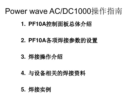
Power wave AC/DC1000操作指南
1. PF10A控制面板总体介绍 2. PF10A各项焊接参数的设置 3. 焊接操作介绍 4. 与设备相关的焊接资料 5. 焊接实例
显示屏2 状态灯 旋钮2
启动 停止
红外接口 焊接模式
弧控
1.PF10A面板介绍
显示屏3
行走模式 冷送焊剂
按钮1
旋钮1
按钮2
2.PF10A各项焊接参数的设置
2.6 起弧、收弧设置-Arc delay time 默认情况下,按一下按钮2,则指示灯start option亮,此时,显示屏上显示Arc delay time,拨动旋钮1可进行延迟时间的设置(0-5s),OFF表示0S。
2.PF10A各项焊接参数的设置
2.6 起弧、收弧设置-Arc strike 设定好ARC DELAY TIME 后再按一下按钮2,指示灯start option及WFS闪烁,显示 屏1上显示Arc strike,此时可拨动旋钮2进行起弧时送丝速度设置(10-200)
2.PF10A各项焊接参数的设置
2.5 Arc control(弧控)设置 -arc 2 balance(对于使用相位发生器的系统) 紧接上一步,再按一下按钮1,显示屏1上显示arc 2 balance (见图),拨动旋 钮1可以在25,75之间进行设置。
2.PF10A各项焊接参数的设置
2.5 Arc control(弧控)设置 -arc 2 phase (对于使用相位发生器的系统) 将Balance设定完成后,再按一下按钮1,显示屏1上显示arc 2 phase (见图), 拨动旋钮1可以在0-270度之间进行设置。 重复上两张幻灯片的步骤可进行arc 3,arc 4的balance 和 phase angel 的设置。
2.PF10A各项焊接参数的设置
2.6 起弧、收弧设置-burn back焊丝回烧时间 Crater time设置完成后,再按一次按钮2,可在0-2s间进行Burn back设置,再按 一下按钮2,则start option灯亮,显示屏上显示为arc delay time,回到默认状态。
3.焊接操作介绍
6 - 3/32’’ (2.4mm)
7 - 5/64’’ (2.0mm)
8 - 1/16’’ (1.6mm)
第二位数字:表示所使用电流的类型
2-60 HZ SINE WAVE 频率为60赫兹的正弦波
3-50HZ SINE WAVE 频率为50赫兹的正弦波
4-CV DC-
恒压模式下的直流正接(工件接正)
2.PF10A各项焊接参数的设置
2.6 起弧、收弧设置-crater time填弧坑时间 Start time设置完成后,再按一下按钮2,显示屏上显示crater time, 旋转旋钮1进行 熄弧时间设置(0-10s),OFF表示熄弧时间为0s,该设置不为0时,可拨动旋 钮2和旋钮3分别进行收弧电流及电压的调节
2.PF10A各项焊接参数的设置
2.6 起弧、收弧设置-start time 设定好arc strike后,再按一下按钮2,显示屏1上显示start time,此时start option, amps, volts都闪烁,拨动旋钮1可在0-0.5s之间进行起弧时间设定,拨动旋钮2和 3进行起弧电流和电压的设置
3.1 Start 按钮启动焊接操作 3.2 Stop 按钮停止焊接操作 3.3 travel 操作架行走模式选择开关
3.3.1 on-小车只要加电就会运动 3.3.2 off-小车停止运动 3.3.3 auto-按下Start后小车自动行走,按下Stop后小车自动停止 3.4 Inch up-回抽丝(用于调整干伸长) 3.5 Inch down-冷送丝(用于装焊丝或调整干伸长)