林肯焊机DC1000
林肯DC---1000+LN--7技术协议

DC—1000埋弧自动焊技术协议甲方(需方)博世热力技术(武汉)有限公司乙方(供方)武汉肯比焊接技术有限公司关于甲方订购1台林肯DC-1000埋弧焊电源,事宜,甲乙双方本着平等互利的原则,就本设备技术问题达成以下协议:1. 设备名称:埋弧自动焊接系统2. 设备规格型号:根据用户对焊接的要求及工件情况,设备配置如下:林肯DC-1000埋弧焊电源1台LT-7轨道式自动送丝机1套3. 设备技术条件3.1 设备用途:埋弧焊自动焊接3.2 主要技术参数:3.2.1 详细说明加工对象的要求、范围3.2.2 设备的详细技术参数(含遵循的技术标准/规范)(一)林肯DC--1000埋弧焊电源额定工作电流1000A额定负载持续率100%输入电源AC三相380V±10%50HZ±2%输出电流范围150——1300A空载电压Max75V接头开关NA---3电源电压调节范围16——46V(二)LT-7轨道式自动送机产品名称LT-7轨道式输入电源115V交流50/60HZ额定输出电流/暂载率600A/100%1100A/100%送丝速度范围 2.5~10.2m/min (100~400英寸/分)行走速度范围0.2~1.8m/min (6~70英寸/分)垂直机头升降调节范围12.7~127mm (1/2~5英寸/分)焊丝尺寸范围 2.4~4.8mm (3/32~3/16英寸)任一侧焊接角与垂直方向最大夹角50°制动角与垂直方向最大夹角30°3.2.3 设备其它技术指标(无)3.3 设备的组成及说明(一)林肯DC--1000埋弧焊电源1、美国林肯DC—1000整流器为六相可控硅半桥弧焊整流器,采用单旋钮电位器控制,应用于半自动和全自动焊接,电弧特性为平特性和降特性两种,可实现单一电源多种用途焊接。
2、DC---1000弧焊整流器适应自动埋弧焊电源,也可做手工弧焊电源、MIG焊、药芯焊丝焊,并且也可以做碳棒直径高达5/8英寸(15.9mm)的碳弧气刨电源。
林肯电气焊接设备操作手册说明书

MUL TI-SOURCEOPERATOR’S MANUALFor use with machines Code 10668October, 2000IM692Safety Depends on YouLinco ln arc welding equipment is designed and built with safety in mind. However, your overall safety can be increased by proper instal-latio n ... and tho ughtful o peratio n on your part.DO NOT INSTALL,OPERATE OR REPAIR THIS EQUIPMENT WITHOUT READ-ING THIS MANUAL AND THE SAFETY PRECAUTIONS CON-TAINED THROUGHOUT.And,most importantly, think before you act and be careful.Copyright © 2000 Lincoln Global Inc.This manual covers equipment which is nolonger in production by The Lincoln Electric Co. Speci cations and availability of optional features may have changed.Mar ‘95Mar ‘95Mar. ‘93for selecting a QUALITY product by Lincoln Electric. We want you to take pride in operating this Lincoln Electric Company product ••• as much pride as we have in bringing this product to you!Read this Operators Manual completely before attempting to use this equipment. Save this manual and keep it handy for quick reference. Pay particular attention to the safety instructions we have provided for your protection.The level of seriousness to be applied to each is explained below:vvOther indicator lights include the amber Thermal light that signals when the long term output current limit has been exceeded. This limit is determined by a ther-mostat sensing the temperature of the negative output lead from the secondary coils. The white Power light indicates when the Control board is energized. The three lights are high intensity LEDs for improved visi-bility in daylight.The Output Power display uses high intensity LEDs to indicate the percentage of full rated output the machine is supplying.Two additional thermostats protect the machine in the case of fan failure or blocked air flow. The SCR heat sink thermostat responds first to loss of air flow at nor-mal output loads. This thermostat will disable the machine output. The transformer iron rear thermostat senses that the lamination (and thus the coil insula-tion) is over heating (which can happen even if the output is disabled). This thermostat will interrupt power to the Control board causing the input contactor to open until the iron cools.The only user controls are an on-off toggle Power switch that energizes the machine and a 10 A circuit breaker protecting the fan auxiliary against short cir-cuits.DESIGN FEATURES - ALL MODELSSPECIFICATIONS,DESIG N FEATURES AND ADVANTAGESCase parts are predominantly stainless steel, the PC boards are potted in trays, the controls are sealed, all machine coils are copper and the whole transformer is varnish dipped to maximize environmental withstand capability. The coils are all conservatively rated for long life.The Multi-Source output regulates against wide changes in output loading and input line voltage varia-tions to supply a consistently stable voltage high enough to allow the Multi-Welds to provide good man-ual electrode capability.SAFETY PRECAUTIONSGENERAL DESCRIPTIONThe Multi-Source is designed to supply power to the Multi-Weld welders. It has a wide range three phase AC input and can be operated on 50 or 60 Hz. The Multi-Source output peak voltage regulates against wide changes in output loading and input line voltage variations to supply a consistently stable voltage high enough to allow the Multi-Welds to provide good man-ual electrode capability.Primary input voltage taps are selected by a single movable link on the reconnect panel. Main trans-former auxiliary windings power the firing circuit and fan motor. The control auxiliary transformer has a sin-gle, wide range primary and is not reconnectable.The Fan As Needed feature is activated by an output current of 20 Adc or a thermostat on the main trans-former iron.An independent safety circuit on the Control board monitors the voltage peaks and opens the input con-tactor if the limit is exceeded. The green Safe Output light indicates when the machine output voltage isFACTORY INSTALLED OPTIONS / ACCESSORIESThere are no factory installed options.FIELD INSTALLED OPTIONS / ACCESSORIESK1735-1 Multi-Weld 350, Multi-process controller.K857, K857-1 Remote Control, Control Multi-Weldremotely (25 or 100 ft.).K1736-1 Distribution Box, Connects up to 10 Multi-Welds.K449 LN-25, Across the arc wire feeder.K1788-1 Roll Cage, Protect power source, facilitate moving, store cable.K1806-1 Multi-Weld Four Pack, Mounting / lift rack for M-S and four M-Ws.K1807-1 Multi-Weld Eight Pack, Mounting / lift rack for M-S and eight M-Ws.S20428Paralleling Kit,Allows two machines toequally share double load.MACHINE CALIBRATION SPECIFICATIONThe Multi-Source digital display is controlled by a cur-rent sensing circuit on the Control board. The display reads 100 when machine output is a little over 40 kW. To recalibrate the display, the machine output may loaded with Multi-Weld welders or resistive grids or a combination of both to obtain an output of 533 Adc as read by a calibrated standard ammeter. Trimmer resistor R49 may be adjusted to cause the display to read 100.This Troubleshooting Guide is provided to help you locate and repair possible machine malfunctions.Simply follow the three-step procedure listed below.Step 1.LOCATE PROBLEM (SYMPTOM).Look under the column labeled “PROBLEM (SYMP-TOMS)”. This column describes possible symptoms that the machine may exhibit. Find the listing that best describes the symptom that the machine is exhibiting.Step 2.POSSIBLE CAUSE.The second column labeled “POSSIBLE CAUSE” liststhe obvious external possibilities that may contribute to the machine symptom.Step 3.RECOMMENDED COURSE OF ACTIONThis column provides a course of action for the Possible Cause, generally it states to contact your local Lincoln Authorized Field Service Facility.If you do not understand or are unable to perform the Recommended Course of Action safely, contact your local Lincoln Authorized Field Service Facility.HOW TO USE TROUBLESHOOTING GUIDEService and Repair should only be performed by Lincoln Electric Factory Trained Personnel.Unauthorized repairs performed on this equipment may result in danger to the technician and machine operator and will invalidate your factory warranty. For your safety and to avoid Electrical Shock, please observe all safety notes and precautions detailed throughout this manual.__________________________________________________________________________5. LEDs 1 through 6 indicate gate signals are being sent to the main SCRs 1 through 6 respectively. If LED2 on the Control board is bright, along with LEDs 7, 8, and 9 on Firing board, and LEDs 1through 6 are unequal in brightness, check to make sure lead 231 between Control board and Firing board is not broken. (If lead 231 is removed while the machine output is at open circuit, the output voltage peaks may be unregulated and cause the over-voltage protection circuit to open the input contactor. The over-voltage protection circuit may disabled by disconnecting lead 222D at the nega-tive output stud or at pin 1 of P2. NOTE: Themachine may not be used for welding with the pro-tection circuit disabled.6. If one or more of LEDs 1 through 6 are off, LEDs 7,8, and 9 are on and the voltage on lead 231 from the Control board (pin 13, P5 to pin 12, P5) is 3 to 13Vdc replace the Firing PCB.PC BOARD TROUBLESHOOTING GUIDE - FIRING P .C.BOARD1. LEDs 1 through 9 must be lit when the Multi-Source is turned on and the Control board is sending an enable signal to the Firing board (pin 7 in P8 is low in reference to common at pin 12 in P5).2. LEDs 7, 8, and 9 indicate AC power being supplied to the P.C. board from auxiliary windings on the main transformer (T1). If a LED is not on, turn the machine off and unplug P8 from the firing board.Turn the machine back on and check the following voltages:3. If all voltages are present, turn power off, and plug P5 back into J5. Turn power back on. If LEDs 7, 8or 9 are still not lit, replace Firing PCB.4. If voltages were not present, check the circuit back through the external dropping resistors to the auxil-iary windings for a possible open resistor or wire.PC BOARD TROUBLESHOOTING GUIDE - CONTROL P .C.BOARD1. The white Power light on the machine control panel indicates that the Control board power supply is being supplied by rectified secondary voltage from the Control transformer (T2) by way of the Power switch and transformer iron rear thermostat.2. LED1 indicates machine output voltage. At normal output voltages, LED1 will be brightly lit.3. LED2 indicates the level of the control signal to the Firing board. The brightness of LED2 is inversely proportional to machine output because the control signal increases as the machine output decreases.4. LED3 lights when the current amplifier senses an output current over about 10 amps and sends a sig-nal to turn the cooling fan on. If LED3 is on but the fan is not , there could be a problem with the fan motor or the fan motor drive circuit (see LED6).5. LED4 says that some signal, either thermostat, out-put current or output over-current is calling for the fan to operate.6. LED5 tells us that the current signal from the shunt is too high. If LED5 is lit for 5-8 seconds, the enable signal to the Firing board is made high to shut off the output SCRs. In the case of a short duration current overload, LED5 may only be briefly litbecause, in normal operation, the machine output immediately goes to zero. Once disabled, the out-put will remain off for about 75 seconds.7. LED6 indicates that the input to the fan motor opto triac driver has been energized. LED6 should be on as long as the fan motor runs. LED6 and the fan motor will be on for about 5 minutes after LED4goes off.8. LED7 will light when the shorted SCR circuit acti-vates. A positive voltage on the negative output stud (AC instead of DC on the output studs) will activate a circuit causing the input contactor to open. This circuit is active only when the enable signal to the Firing board is high (the output is off).The contactor will remain open (and the whitePower light will remain on) until the Power switch is turned off (or the input power to the machine is oth-erwise removed) for about 1 second and then turned on again.9. The green Safe Output light on the control panel when the machine output voltage is present and safe. It lights when the machine output is between 40 Vdc and 113 volts peak. 10. The yellow Thermal light on the front panel lightswhen the open thermostat signal is sent to the fan control and output disable circuits.Now Available...12th EditionThe Procedure Handbook of Arc WeldingWith over 500,000 copies of previous editions published since 1933, the Procedure Handbook is considered by many to be the “Bible” of the arc welding industry.This printing will go fast so don’t delay. Place your order now using the coupon below.The hardbound book contains over 750 pages of welding information, techniques and procedures. Much of this material has never been included in any other book.A must for all welders, supervisors, engineers and designers. Many welding instructors will want to use the book as a reference for all students by taking advantage of the low quantity discount prices which include shipping by 4th class parcel post.$15.00postage paid U.S.A. MainlandHow To Read Shop DrawingsThe book contains the latest information and application data on the American Welding Society Standard Welding Symbols. D etailed discussion tells how engineers and draftsmen use the “short-cut” language of symbols to pass on assembly and welding information to shop personnel.Practical exercises and examples develop the reader’s ability to visualize mechanically drawn objects as they will appear in their assembled form.187 pages with more than 100 illustrations. Size 8-1/2” x 11”Durable, cloth-covered board binding.$4.50postage paid U.S.A. MainlandNew Lessons in Arc WeldingLessons, simply written, cover manipulatory techniques;machine and electrode characteristics; related subjects,such as distortion; and supplemental information on arc welding applications, speeds and costs. Practice materials,exercises, questions and answers are suggested for each lesson.528 pages, well illustrated, 6” x 9” size, bound in simulated,gold embossed leather.$5.00postage paid U.S.A. MainlandNeed Welding Training?The Lincoln Electric Company operates the oldest and most respected Arc Welding School in the United States at its corporate headquarters in Cleveland, Ohio. Over 100,000stu-dents have graduated. Tuition is low and the training is “hands on”For details write:Lincoln Welding School 22801 St. Clair Ave.Cleveland, Ohio 44117-1199.and ask for bulletin ED-80 or call 216-383-2259 and ask for the Welding School Registrar.Lincoln Welding SchoolBASIC COURSE $700.005 weeks of fundamentalsThere is a 10%discount on all orders of $50.00 or more for shipment at one time to one location.Orders of $50 or less before discount or orders outside of North America must be prepaid with charge, check or money order in U.S. Funds Only.Prices include shipment by 4th Class Book Rate for U.S.A. Mainland Only.Please allow up to 4 weeks for delivery.UPS Shipping for North America Only.All prepaid orders that request UPS shipment please add:$5.00For order value up to $49.99$10.00For order value between $50.00 & $99.99$15.00For order value between $100.00 & $149.00For North America invoiced orders over $50.00 & credit card orders, if UPS is requested, it will be invoiced or charged to you at cost.Outside U.S.A. Mainland order must be prepaid in U.S. Funds. Please add $2.00 per book for surface mail or $15.00 per book for air parcel post shipment.METHOD OF PAYMENT:(Sorry, No C.O.D. Orders)CHECK ONE:Name:_______________________________________________Please Invoice (only if order is over $50.00)Address:_______________________________________________Check or Money Order Enclosed, U.S. Funds only _______________________________________________Credit Card - Telephone:_______________________________________________Signature as it appears on Charge Card:Account No.Exp Date|_|_||_|_|______________________Month YearUSE THIS FORM TO ORDER:Order from:BOOK DIVISION, The Lincoln Electric Company, 22801 St. Clair Avenue, Cleveland, Ohio 44117-1199BOOKS OR FREE INFORMATIVE CATALOGS Telephone: 216-383-2211 or, for fastest service, FAX this completed form to: 216-361-5901.Lincoln Welding School Titles:Price Code QuantityCost(ED-80)New Lessons in Arc Welding $5.00L Seminar Information Procedure Handbook “Twelfth Edition”$15.00PH (ED-45)How to Read Shop Drawings $4.50H Educational Video Information Incentive Management $5.00IM (ED-93) A New Approach to Industrial Economics $5.00NA James F. Lincoln Arc Welding The American Century of John C. Lincoln $5.00AC Foundation Book Information Welding Preheat Calculator $3.00WC-8(JFLF-515)Pipe Welding Charts $4.50ED-89SUB TOTALAdditional Shipping Costs if anyJapaneseChineseKoreanArabicREAD AND UNDERSTAND THE MANUFACTURER’S INSTRUCTION FOR THIS EQUIPMENT AND THE CONSUMABLES TO BE USED AND FOLLOW YOUR EMPLOYER’S SAFETY PRACTICES.SE RECOMIENDA LEER Y ENTENDER LAS INSTRUCCIONES DEL FABRICANTE PARA EL USO DE ESTE EQUIPO Y LOS CONSUMIBLES QUE VA A UTILIZAR, SIGA LAS MEDIDAS DE SEGURIDAD DE SU SUPERVISOR.LISEZ ET COMPRENEZ LES INSTRUCTIONS DU FABRICANT EN CE QUI REGARDE CET EQUIPMENT ET LES PRODUITS A ETRE EMPLOYES ET SUIVEZ LES PROCEDURES DE SECURITE DE VOTRE EMPLOYEUR.LESEN SIE UND BEFOLGEN SIE DIE BETRIEBSANLEITUNG DER ANLAGE UND DEN ELEKTRODENEINSATZ DES HER-STELLERS. DIE UNFALLVERHÜTUNGSVORSCHRIFTEN DES ARBEITGEBERS SIND EBENFALLS ZU BEACHTEN.JapaneseChineseKoreanArabicLEIA E COMPREENDA AS INSTRUÇÕES DO FABRICANTE PARA ESTE EQUIPAMENTO E AS PARTES DE USO, E SIGA AS PRÁTICAS DE SEGURANÇA DO EMPREGADOR.。
林肯DC1000-NA5自动埋弧焊机维修经验
林肯DC1000/NA5自动埋弧焊机维修经验
本内容介绍了林肯埋弧焊机的维修经验,这种机器在国内埋弧自动生产线用的非常多,焊接性能和焊接质量都很好,最重要的是质量可靠,经久耐用。
但并不代表永远不会坏。
由于是进口机,坏了维修会比较麻烦,一般控制板坏了林肯公司以及经销商都不会进行维修,只是更换新板。
而且控制板的价格都不菲,少则几千,贵的几万。
为了减少客户的维修成本,小弟对林肯一系列的进口和国产焊机整机电路以及控制板工作原理进行了一些研究,学习到一点皮毛,这回正好运用这点皮毛技术为客户解决一点难题,为客户节约了维修成本,最大限度缩短了设备停工时间,将机器故障带来的损失减少到了最少。
好了废话不多说,来看看林肯机器到底是怎幺修的,有图有真相哦。
两台排排坐的林肯DC1000埋弧焊主机。
林肯电焊机

林肯电气PWF-4 & 2 送丝机的送丝速度为 1.5米/分钟 到 20米/分钟 , 和PANA 相类似. POWERPLUS II 500 在全程输出范围内可以进行精确的控制.
POWERPLUS ll 500
测试结果 稳定的输出 – 高 & 低
The Current Range
POWERPLUSTM II 500
附件
气表
国内: 36V CO2 加热器 出口: 220V CO2 加热器
遥控电压盒
和LN-25 送丝机相连的远程电压控制盒.
安装脚轮组件
备有4个脚轮,销子,支架和安装螺丝. 作为选配件可以方便的安装在焊机底部.
POWERPLUS ll 500
林肯电气中国荣幸地向大家发布最新一代性能可靠的 POWERPLUS 焊接电源. 我们的研发工程师根据现场用户的大量使用情况和市场反馈,设 计了此 POWERPLUS焊接电源. 焊接电源产品一些关键的因素如:成本,焊接性能和可靠性是我 们首先关注的问题.
精准的控制
POWERPLUSTM II 500
前面板特征:
电压 / 电流表: 新的数字表,经过校准,当电弧结束后,电压 / 电流表 能保留几秒的焊接参数显示. 收弧电压 / 电流 2/4 步 选择 检气 / 焊接 选择 过热指示灯 — 过载保护: 故障代码可以在电压 / 电流表上显示,为维修带来极 大的方便.
4 步 / 2 步 焊接控制
4 步控制
2 步控制
POWERPLUSTM II 500
收弧控制
POWERPLUSTM II 500
PWF 送丝机
PWF-2 PWF-4 PWF-2 Plus PWF-4 Plus PWF-2 (带1米快速接头, 船厂专用)
林肯电焊机说明书

MAGNUM® PRO ROBOTIC GUNS DESIGNED FOR LONG LIFE.Thru-ArmExternal DressPublication E12.03 | Issue Date 07/24/20• Patented HexConnect ™ Gun Bushing- Delivers superior mechanical and electrical connectionresulting in longer expendable life. - Resists twisting and provides more points of contactfor current flow.• Fixed Electrical Connection- Robust design resists fatigue - Lasted over 1 milliontortuous flex cycles in extreme lab testing. - Competitive rotating designs can cause micro-arcingresulting in arc instability and potential shorter gun life.Tough Teflon ® Insulation• Single Tool Center Point (TCP) - No need to re-programwhen switching between the Magnum ® PRO 350 and 550 amp expendables.• Contact Tip Technology - Copper Plus ™ - more copper for better heat dissipation.- Anti-Seize ™ thread design on contact tips and diffuser.• Aluminum- Aircraft grade aluminum outer tube extends service.• Copper- High quality copper inner tube enhances electrical conductivity.Contact Tip for up to 550 AMagnum ®PRO 550 A ExpendablesGun Tube Insulator 550 A(1) 550 only350 A and 550 A Magnum ® PRO Expendable Parts are interchangeable. Interchanging will require gun tube insulator and gas diffuser changes. Customersmay choose to change expendable parts to standardize stocking parts or to make the gun more compact for tight spaces.(2)(2)Gas Diffuser for up to 550 A Slip-onGas Diffuser for up to 550 AThread-on (2) Jump liners and wire guides are only used on Thru-arm torches with wire brake.Gas Nozzlefor 550Thread-on 1/8 in. (3.2 mm) RecessedBottleneck Gas Nozzle for 550Thread-on 1/8 in. (3.2 mm)RecessedGENERAL OPTIONSRobotic Gun Tube Straightener Used in the event of a robot crash to check and correct robotic gun tube alignment. OrderK3193-1(Compatible with all standard KP3056-XX and KP3057-XX gun tubes)K3193-2(Compatible with all standard KP3354-XX and KP3355-XX gun tubes)EXTERNAL DRESS OPTIONS External Dress Torch Mounting KitsDesigned to mount the External Dress torch in the proper orientation for the application and fixturing presented to the robot. Consult Automation Division for correct mounting kit selection assistance. OrderKP2769-2222 Degree – Lincoln Electric Tool Center Point (TCP)KP2769-4545 Degree – Lincoln Electric Tool Center Point (TCP)KP2769-180180 Degree – Lincoln Electric Tool Center Point (TCP)KP3054-2222 Degree – Tregaskiss ® TCP, FANUC ® Solid Mount KP3055-2222 Degree – Tregaskiss ® TCP, Tregaskiss ® Clutch Mount KP3499-2222 Degree - Lincoln Electric Tool Center Point (TCP)for ABB and KUKA Robot Arms KP3499-4545 Degree - Lincoln Electric Tool Center Point (TCP)for ABB and KUKA Robot Arms KP3499-180180 Degree - Lincoln Electric Tool Center Point (TCP)for ABB and KUKA Robot ArmsExternal Dress Break-Away Disks Replaceable mounting interface disk designed to protect the robot arm by absorbing the effects of any damage in the event of a robot work envelope collision. OrderKP3194-1External Dress Break-Away Disk (Fanuc iB)KP3194-2External Dress Break-Away Disk (Fanuc 50 iC)KP3194-3External Dress Break-Away Disk (Fanuc iC)KP3194-4External Dress Break-Away Disk(ABB2600)KP3194-5External Dress Break-Away Disk(KR6, KR8, KR10)THRU-ARM OPTIONSThru-Arm Break-Away Disks Replaceable mounting interface disk designed to protect the robot arm by absorbing the effects of any damage in the event of a robot work envelope collision.See specification chart below for correct part number rWire Brake PlugPlug when removing wire brake from K4307-2 Order K3563-1Nose Cone Assemblies See specification chart below for correct part numberTorch HousingsSee specification chart below for correct part numberAir Blast KitBlows spatter from the nozzle orifice. Includes 20 ft (6.1 m) hose and fitting. Order K3352-1Thru-Arm Replacement Cable AssembliesSee specification chart below for correct part numberK466-10(1) K1500-3 Gun Receiver Bushing is required for Power Feed 10 series, LF series and LN-25 PRO wire feeders.(2)Terms are tradmarks of Illinois Tool Works.[3]Included with External Dress Torch [4]Included with Thru-Arm Torch(3)(3) Note that external dress guns include a 22 degree Lincoln Electric TCP gooseneck,liner and consumables. Mounting kit is not included.®®®®®®The Lincoln Electric Company22801 St. Clair Avenue • Cleveland, OH • 44117-1199 • U.S.A.C USTO ME R ASSI STA NC E PO LICYThe business of The Lincoln Electric Company ® is manufacturing and selling high quality welding equipment, consumables, and cutting equipment. Our challenge is to meet the needs of our customers and to exceed their expectations. On occasion, purchasers may ask Lincoln Electric for information or advice about their use of our products. Our employees respond to inquiries to the best of their ability based on information provided to them by the customers and the knowledge they may have concerning the application. Our employees, however, are not in a position to verify the information provided or to evaluate the engineering requirements for the particular weldment. Accordingly, Lincoln Electric does not warrant or guarantee or assume any liability with respect to such information or advice. Moreover, the provision of such information or advice does not create, expand, or alter any warranty on our products. Any express or implied warranty that might arise from the information or advice, including any implied warranty of merchantability or any warranty of fitness for any customers’ particular purpose is specifically disclaimed.Lincoln Electric is a responsive manufacturer, but the selection and use of specific products sold by Lincoln Electric is solely within the control of, and remains the sole responsibility of the customer. Many variables beyond the control of Lincoln Electric affect the results obtained in applying these types of fabrication methods and service requirements.Subject to Change – This information is accurate to the best of our knowledge at the time of printing. Please refer to for any updated information.For best welding results with Lincoln Electric equipment, always use Lincoln Electric consumables. Visit for more detail.All trademarks and registered trademarks are the property of their respective owners.。
林肯电力(Lincoln Electric)生产的焊接和切割设备操作手册说明书

RANGER ™3 PHASEOPERATOR’S MANUALFor Machines with Code Number 11079IM831October, 2004Safety Depends on YouLincol n arc wel ding and cutting equipment is designed and buil t with safety in mind. However, your overall safety can be increased by proper installation ... and thought-ful operation on your part.DO NOT INSTALL, OPERATE OR REPAIR THIS EQUIPMENT WITHOUT READING THIS MANUAL AND THE SAFETY PRECAUTIONS CONTAINED THROUGHOUT.And, most importantl y, think before you act and be careful.Copyright © 2004 Lincoln Global Inc.This manual covers equipment which is nolonger in production by The Lincoln Electric Co. Speci cations and availability of optional features may have changed.Mar ‘95Mar. ‘93vvfor selecting a QUALITY product by Lincoln Electric. We want you to take pride in operating this Lincoln Electric Company product ••• as much pride as we have in bringing this product to you!1. Output rating in watts is equivalent to volt - amperes at unity factor.Output voltage is within +/-10% at all loads up to rated capacity.When welding available auxiliary power will be reduced.Internal combustion engines are designed to run in a level condition which is where the optimum perfor-mance is achieved. The maximum angle of operation for the engine is 15 degrees from horizontal in any direction. If the engine is to be operated at an angle,provisions must be made for checking and maintain-ing the oil at the normal (F ULL) oil capacity in the crankcase in a level condition.When operating at an angle, the effective fuel capaci-ty will be slightly less than the specified 9 gallons (34Liters).LIFTINGThe RANGER 3 PHASE weighs approximately 575lbs.(261kg) with a full tank of gasoline. A lift bail is mounted to the machine and should always be used when lifting the machine.HIGH ALTITUDE OPERATIONIf the RANGER 3 PHASE will be consistently operat-ed at altitudes above 5000 ft(1524m), a carburetor jet designed for high altitudes should be installed. This will result in better fuel economy, cleaner exhaust,and longer spark plug life. It will not give increased power which is decreased at higher altitudes. Engine horsepower is reduced by 3.5% per 1000feet(304.8m) for altitudes above 377 feet(115m).Do not operate a RANGER 3 PH ASE with a highaltitude jet installed at altitudes below 5000ft.(1524m) This will result in the engine runningtoo lean and result in higher engine operatingtemperatures which can shorten engine life.-----------------------------------------------------------------------Contact your local Kohler Authorized Dealer for highaltitude jet kits that are available from the engine •Shut off welder and allow muffler to cool beforetouching muffler.------------------------------------------------------------------------The RANGER 3 PHASE is shipped with the exhaust coming out on the left side. The exhaust can be changed to the opposite side by removing the two screws that hold the exhaust port cover in place and installing the cover on the opposite side. (Operating the RANGER 3 PHASE without the cover in place will result in a higher noise level and no increase in machine output.)LOCATION / VENTILATIONThe welder should be located to provide an unrestrict-ed flow of clean, cool air to the cooling air inlets and to avoid heated air coming out of the welder recirculating back to the cooling air inlet. Also, locate the welder so that engine exhaust fumes are properly vented to an outside area.STACKINGRANGER 3 PHASE machines cannot be stacked.CONNECTION OF LINCOLN ELECTRIC WIRE FEEDERSShut off welder before making any electrical connections.------------------------------------------------------------------------WIRE FEED (CONSTANT VOLTAGE)CONNECTION OF LN-15 ACROSS-THE-ARC WIRE FEEDERThe LN-15 has an internal contactor and the electrode is not energized until the gun trigger is closed. When the gun trigger is closed the wire will begin to feed and the welding process is started.a. Shut the welder off.b. Set the Polarity switch to the desired polarity,either DC (-) or DC (+).c. Attach the single lead from the front of the LN-15to work using the spring clip at the end of the lead.This is a control lead to supply current to the wire feeder motor; it does not carry welding current.d.Set the “RANGE” switch to the “WIRE F EED-CV”position e. Place the Engine switch in the “Auto Idle” position.f. Adjust the wire feed speed at the LN-15 and adjust the welding voltage with the output “CONTROL” at the welder. Output “CONTROL” must be set above 3.Note:LN-15 Control Cable model will not work with• Lift only with equipment of ade-quate lifting capacity.• Be sure machine is stable when lift-ing.• Do not lift this machine using lift bail if it is equipped with a heavy accessory such as trailer or gas cylinder.FALLING• Do not lift machine if lift bail isEQUIPMENT can damaged.cause injury. • Do not operate machine whilesuspended from lift bail.--------------------------------------------------------------------------------CONNECTION OF TH E LN-25 TO TH E RANGER 3PHASE•Shut the welder off.•Connect the electrode cable from the LN-25 to the “ELECTRODE” terminal of the welder.Connect the work cable to the “TO WORK” termi-nal of the welder.•Position the welder “Polarity” switch to thedesired polarity, either DC (-) or DC (+).•Position the “RANGE” switch to the “WIREFEED” position.•Attach the single lead from the LN-25 control boxto the work using the spring clip on the end of the lead - it carries no welding current.•Place the engine switch in the “AUTO” position.•Adjust wire feed speed at the LN-25 and adjustthe welding voltage with the output “CONTROL”at the welder.NOTE:The welding electrode is energized at all times, unless an LN-25 with built-in contactor is used.If the output “CONTROL” is set below “3”, the LN-25contactor may not pull in.CONNECTION OF K930-2 TIG MODULE TO TH E RANGER 3 PHASE.The TIG Module is an accessory that provides high frequency and shielding gas control for AC and DC GTAW (TIG) welding. See IM528 supplied with the TIG Module for installation instructions.Note: The TIG Module does not require the use of a high frequency bypass capacitor. However, if the RANGER 3 PHASE is used with any other high fre-quency equipment, the bypass capacitor must be installed, order kit T12246.INSTRUCTIONSADDITIONAL SAFETY PRECAUTIONSAlways operate the welder with the roof and case sides in place as this provides maximum protection from moving parts and assures proper cooling air flow.Read and understand all Safety Precautions before operating this machine. Always follow these and any other safety procedures included in this manual and in the Engine Owner’s Manual.WELDER OPERATIONWELDER OUTPUT• Maximum Open Circuit Voltage at 3700 RPM is 80 Volts RMS.*Current Sensing for Automatic Idle.(Receptacle viewed from front of Machine)(FOR ALL SINGLE AND ZTHREE PHASE LOADS)TABLE lllELECTRICAL DEVICE USE WITH THE RANGER 3 PHASE.Type Common Electrical Devices Possible ConcernsResistive Heaters, toasters, incandescent NONElight bulbs, electric range, hotpan, skillet, coffee maker.Capacitive TV sets, radios, microwaves, Voltage spikes or high voltageappliances with electrical control.regulation can cause the capac-itative elements to fail. Surgeprotection, transient protection,and additional loading is recom-mended for 100% fail-safeoperation. DO NOT RUNTHESE DEVICES WITHOUTADDITIONAL RESISTIVE TYPELOADS.Inductive Single-phase induction motors, These devices require largedrills, well pumps, grinders, small current inrush for starting.refrigerators, weed and hedge Some synchronous motors maytrimmers be frequency sensitive to attainmaximum output torque, butthey SHOULD BE SAFE fromany frequency induced failures. Capacitive/Inductive Computers, high resolution TV sets,An inductive type line condition-complicated electrical equipment. er along with transient andsurge protection is required,and liabilities still exist. DONOT USE THESE DEVICESWITH A RANGER 3 PHASE The Lincoln Electric Company is not responsible for any damage to electrical components improperly connect-ed to the RANGER 3 PHASE.1.Install a double pole, double throw switch betweenthe power company meter and the premises dis-connect.Switch rating must be the same or greater than thecustomer’s premises disconnect and service over-current protection.2.Take necessary steps to assure load is limited tothe capacity of the RANGER 3 PHASE by installinga 40 amp 240V double pole circuit breaker.Maximum rated load for the 240V auxiliary is 40amperes. Loading above 40 amperes will reduceoutput voltage below the allowable -10% of ratedvoltage which may damage appliances or othermotor-driven equipment.3.Install a 50 amp 120/240V plug (NEMA type 14-50)to the Double Pole Circuit Breaker using No. 8, 4conductor cable of the desired length. (The 50 amp120/240V plug is available in the optional plug kit.)4.Plug this cable into the 50 amp 120/240V recepta-cle on the RANGER 3 PHASE case front.*Each duplex receptacle is limited to 20 amps.**Not to exceed 40A per 120VAC branch circuit whensplitting the 240 VAC output.***Use of 3-Phase AC poower is not recommendedwhile welding.LOADNATIONAL ELECTRICAL CODE FOR ALTERNATE WIRESIZE RECOMMENDATIONS.SUMMARY OF WELDING PROCESSESThis Troubleshooting Guide is provided to help you locate and repair possible machine malfunctions.Simply follow the three-step procedure listed below.Step 1.LOCATE PROBLEM (SYMPTOM).Look under the column labeled “PROBLEM (SYMP-TOMS)”. This column describes possible symptoms that the machine may exhibit. Find the listing that best describes the symptom that the machine isexhibiting.Step 2.POSSIBLE CAUSE.The second column labeled “POSSIBLE CAUSE ” lists the obvious external possibilities that may contribute to the machine symptom.Step 3.RECOMMENDED COURSE OF ACTIONThis column provides a course of action for the Possible Cause, generally it states to contact your local Lincoln Authorized Field Service Facility.If you do not understand or are unable to perform the Recommended Course of Action safely, contact your local Lincoln Authorized Field Service Facility.HOW TO USE TROUBLESHOOTING GUIDEService and Repair should only be performed by Lincoln Electric Factory Trained Personnel.Unauthorized repairs performed on this equipment may result in danger to the technician and machine operator and will invalidate your factory warranty. For your safety and to avoid Electrical Shock, please observe all safety notes and precautions detailed throughout this manual.__________________________________________________________________________R A N G E R 3 P H A S E/ L N -15A N D L N -25 A C R O S S T H E A R C C O N N E C T I O N D I A G R A MM 20266JapaneseChineseKoreanArabicREAD AND UNDERSTAND THE MANUFACTURER’S INSTRUCTION FOR THIS EQUIPMENT AND THE CONSUMABLES TO BE USED AND FOLLOW YOUR EMPLOYER’S SAFETY PRACTICES.SE RECOMIENDA LEER Y ENTENDER LAS INSTRUCCIONES DEL FABRICANTE PARA EL USO DE ESTE EQUIPO Y LOS CONSUMIBLES QUE VA A UTILIZAR, SIGA LAS MEDIDAS DE SEGURIDAD DE SU SUPERVISOR.LISEZ ET COMPRENEZ LES INSTRUCTIONS DU FABRICANT EN CE QUI REGARDE CET EQUIPMENT ET LES PRODUITS A ETRE EMPLOYES ET SUIVEZ LES PROCEDURES DE SECURITE DE VOTRE EMPLOYEUR.LESEN SIE UND BEFOLGEN SIE DIE BETRIEBSANLEITUNG DER ANLAGE UND DEN ELEKTRODENEINSATZ DES HER-STELLERS. DIE UNFALLVERHÜTUNGSVORSCHRIFTEN DES ARBEITGEBERS SIND EBENFALLS ZU BEACHTEN.JapaneseChineseKoreanArabicLEIA E COMPREENDA AS INSTRUÇÕES DO FABRICANTE PARA ESTE EQUIPAMENTO E AS PARTES DE USO, E SIGA AS PRÁTICAS DE SEGURANÇA DO EMPREGADOR.。
DC_1500林肯焊机的故障诊断

DC—1500林肯焊机的故障诊断樊东海(宝鸡石油钢管厂 721008) 摘 要 简要叙述了林肯焊机的结构特点及控制调节电路的基本原理,介绍了三种典型故障的产生原因和诊断路径,供维修时参考。
主题词 焊机 原理 故障 分析 1 电路结构特点及基本原理DC—1500林肯焊机按其功能可分为主电路、操作电路、控制调节系统和保护电路四大部分。
1.1 主电路及操作电路主电路采用带平衡电抗器的双反星形可控硅整流电路,比起三相半波整流和三相桥式整流具有以下特点:(1)输出电压稳定,脉动小;(2)消除了整流变压器的直流磁化,变压器二次绕组的利用率高,体积小;(3)提高了整流元件承受负载的能力,输出电流比三相桥式整流电路增加一倍,适宜于作为低电压、大电流整流,整流效率高;(4)整流变压器采用不同的连接方式,可用380V或460V两种电压供电。
操作电路采用交流115V电源供电,电路中串接有过流、过热保护接点和远控操作控制接点3CR,近控时将3CR短接,见图1。
图1 主电路及操作电路原理图·40·焊管·第21卷第3期·1998年5月 1.2 控制调节系统控制调节系统由控制板、触发板和NA —5S 操作箱构成。
按其功能可分为给定、前置放大、综合反馈、电流截止负反馈、主调节器、触发电路和保护电路七大部分。
图2为焊机系统方框图。
图2 焊机系统方框图1.2.1 给定电路给定电路的主要作用是为主调节器提供一个可调的输入信号。
同时整定焊机的最大和最小输出值。
另外,由四个二极管组成的负逻辑或门电路将给定输入电压信号送到保护电路,当给定输入因任一端断线造成电位过低时,保护立即动作,将电源跳开,见图3。
1.2.2 主调节器主调节器是将给定信号和综合反馈信号经差动放大后,产生一个移相控制电压来控制触发脉冲的移相,从而控制了焊机的输出。
同时由模拟开关Q 6控制,在起弧时使移相控制电压最大,将可控硅导通角推到最小,以减少起弧时的冲击(见图4)。
林肯电子公司的高压电焊机说明书
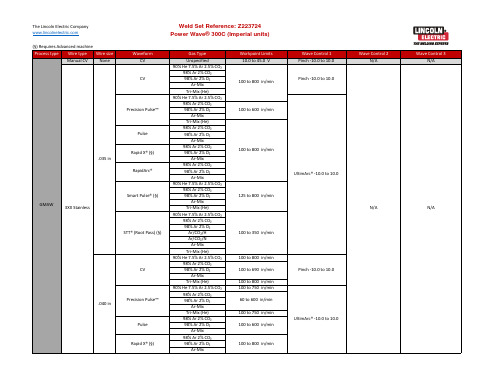
Ar-Mix Tri-Mix (He) 90% He 7.5% Ar 2.5% CO₂ 98% Ar 2% CO₂ 98% Ar 2% O₂
100 to 625 in/min
75 to 500 in/min
75 to 495 in/min
75 to 780 in/min
75 to 760 in/min
100 to 510 in/min
90 to 225 in/min
Wave Control 1 Pinch -10.0 to 10.0 UltimArc® -10.0 to 10.0 Pinch -10.0 to 10.0 UltimArc® -10.0 to 10.0 UltimArc® -10.0 to 10.0 Pinch -10.0 to 10.0 UltimArc® -10.0 to 10.0 Pinch -10.0 to 10.0 UltimArc® -10.0 to 10.0 Pinch -10.0 to 10.0 UltimArc® -10.0 to 10.0 UltimArc® -10.0 to 10.0
100 to 600 in/min
100 to 645 in/min 100 to 625 in/min 100 to 645 in/min 90 to 250 in/min 125 to 700 in/min 150 to 750 in/min 125 to 800 in/min
Wave Control 1 UltimArc® -10.0 to 10.0