EIGRP分解实验一
EIGRP实验配置过程详解
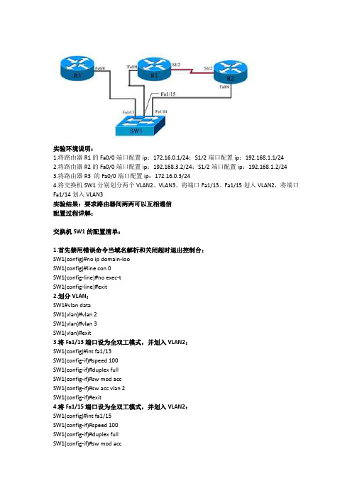
实验环境说明:1.将路由器R1的Fa0/0端口配置ip:172.16.0.1/24;S1/2端口配置ip:192.168.1.1/242.将路由器R2的Fa0/0端口配置ip:192.168.3.2/24;S1/2端口配置ip:192.168.1.2/243.将路由器R3 的Fa0/0端口配置ip:172.16.0.3/244.将交换机SW1分别划分两个VLAN2、VLAN3,将端口Fa1/13、Fa1/15划入VLAN2,将端口Fa1/14划入VLAN3实验结果:要求路由器间两两可以互相通信配置过程详解:交换机SW1的配置清单:1.首先禁用错误命令当域名解析和关闭超时退出控制台:SW1(config)#no ip domain-looSW1(config)#line con 0SW1(config-line)#no exec-tSW1(config-line)#exit2.划分VLAN:SW1#vlan dataSW1(vlan)#vlan 2SW1(vlan)#vlan 3SW1(vlan)#exit3.将Fa1/13端口设为全双工模式,并划入VLAN2:SW1(config)#int fa1/13SW1(config-if)#speed 100SW1(config-if)#duplex fullSW1(config-if)#sw mod accSW1(config-if)#sw acc vlan 2SW1(config-if)#exit4.将Fa1/15端口设为全双工模式,并划入VLAN2:SW1(config)#int fa1/15SW1(config-if)#speed 100SW1(config-if)#duplex fullSW1(config-if)#sw mod accSW1(config-if)#sw acc vlan 2SW1(config-if)#exit5.将Fa1/14端口设为全双工模式,并划入VLAN3:SW1(config)#int fa1/14SW1(config-if)#speed 100SW1(config-if)#duplex fullSW1(config-if)#sw mod accSW1(config-if)#sw acc vlan 3SW1(config-if)#exit路由器R1的配置清单:1.首先禁用错误命令当域名解析和禁用超时退出控制台:R1(config)#no ip domain-looR1(config)#line con 0R1(config-line)#no exec-tR1(config-line)#exit2.将Fa0/0端口设为全双工模式并配置ip:R1(config)#int fa0/0R1(config-if)#speed 100R1(config-if)#duplex fullR1(config-if)#ip add 172.16.0.1 255.255.255.0R1(config-if)#no shutR1(config-if)#exit3.为S1/2端口配置ip:R1(config)#int s1/2R1(config-if)#ip add 192.168.1.1 255.255.255.0R1(config-if)#no shutR1(config-if)#exit4.在路由器R1上配置EIGRP:R1(config)#router eigrp 100R1(config-router)#no auto-summaryR1(config-router)#network 172.16.0.1 0.0.0.0R1(config-router)#network 192.168.1.1 0.0.0.255R1(config-router)#exitR1(config)#exit路由器R2的配置清单:1.首先禁用错误命令当域名解析和禁用超时退出控制台:R2(config)#no ip domain-looR2(config)#line con 0R2(config-line)#no exec-tR2(config-line)#exit2.将Fa0/0端口设为全双工模式并配置ip:R2(config)#int fa0/0R2(config-if)#speed 100R2(config-if)#duplex fullR2(config-if)#ip add 192.168.3.2 255.255.255.0R2(config-if)#no shutR2(config-if)#exit3.为S1/2端口配置ip:R2(config)#int s1/2R2(config-if)#ip add 192.168.1.2 255.255.255.0R2(config-if)#no shutR2(config-if)#exit4.在路由器R2上配置EIGRP:R2(config)#router eigrp 100R2(config-router)#network 192.168.3.0 0.0.0.255R2(config-router)#network 192.168.1.0 0.0.0.255R2(config-router)#exitR2(config)#exit路由器R3的配置清单:1.首先禁用错误命令当域名解析和禁用超时退出控制台:R3(config)#no ip domain-looR3(config)#line con 0R3(config-line)#no exec-tR3(config-line)#exit2.将Fa0/0端口设为全双工模式并配置ip:R3(config)#int fa0/0R3(config-if)#speed 100R3(config-if)#duplex fullR3(config-if)#ip add 172.16.0.3 255.255.255.0R3(config-if)#no shutR3(config-if)#exit3.在路由器R3上配置EIGRP:R3(config)#router eigrp 100R3(config-router)#no auto-summaryR3(config-router)#network 172.16.0.3 0.0.0.0R3(config-router)#exitR3(config)#exit验证EIGRP配置:查看每台路由器的邻居表:#show ip eigrp neiR1的邻居表:R1#show ip eigrp neiIP-EIGRP neighbors for process 100H Address Interface Hold Uptime SRTT RTO Q Seq(sec) (ms) Cnt Num1 172.16.0.3 Fa0/0 11 00:00:48 168 1008 0 40 192.168.1.2 Se1/2 14 00:25:23 244 1464 0 3R2的邻居表:R2#show ip eigrp neiIP-EIGRP neighbors for process 100H Address Interface Hold Uptime SRTT RTO Q Seq(sec) (ms) Cnt Num0 192.168.1.1 Se1/2 14 00:28:34 195 1755 0 5R3的邻居表:R3r#show ip eigrp neiIP-EIGRP neighbors for process 100H Address Interface Hold Uptime SRTT RTO Q Seq(sec) (ms) Cnt Num0 172.16.0.1 Fa0/0 12 00:02:07 134 804 0 8实验的最终结果是每台路由器之间都可以ping通其他的路由器,实验过程到此结束。
思科实验-实验6
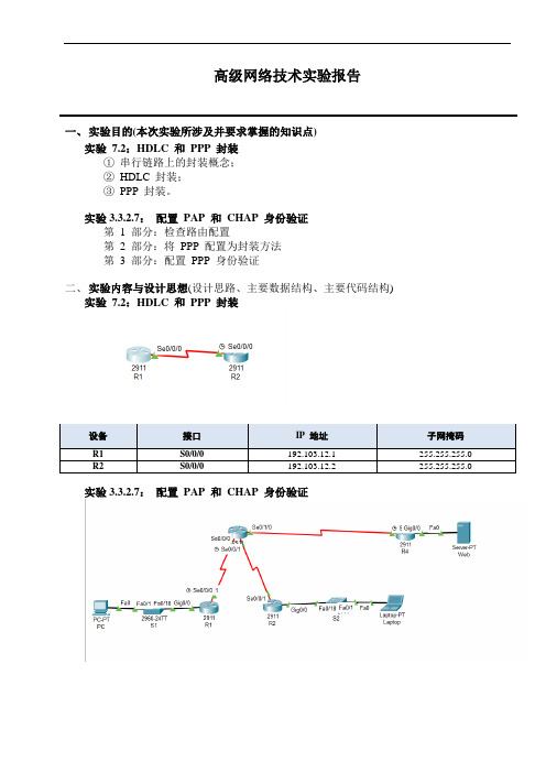
高级网络技术实验报告一、实验目的(本次实验所涉及并要求掌握的知识点)实验7.2:HDLC 和PPP 封装①串行链路上的封装概念;②HDLC 封装;③PPP 封装。
实验3.3.2.7:配置PAP 和CHAP 身份验证第 1 部分:检查路由配置第 2 部分:将PPP 配置为封装方法第 3 部分:配置PPP 身份验证二、实验内容与设计思想(设计思路、主要数据结构、主要代码结构)实验7.2:HDLC 和PPP 封装实验3.3.2.7:配置PAP 和CHAP 身份验证三、实验使用环境(本次实验所使用的平台和相关软件)WIN10Cisco Packet Tracer四、实验步骤和调试过程(实验步骤、测试数据设计、测试结果分析)实验7.2:HDLC 和PPP 封装1、配置R1Router>enRouter#conf tRouter(config)#hostname R1Router(config)#int s0/0/0Router(config-if)#ip address 192.103.12.1 255.255.255.0Router(config-if)#no shut2、配置R2Router>enRouter#conf tRouter(config)#hostname R2R2(config)#int s0/0/0R2(config-if)#clock rate 128000R2(config-if)#ip address 192.103.12.2 255.255.255.0 R2(config-if)#no shut3、检查链路连通性和默认封装R1#show interfaces s0/0/0该接口的默认封装为HDLC 封装4、改变串行链路两端的接口封装为PPP 封装并检查R1(config)#int s0/0/0R1(config-if)#encapsulation pppR2(config)#int s0/0/0R2(config-if)#encapsulation pppshow interface s0/0/0该接口的封装为PPP 封装网络层支持IP 和CDP 协议5、实验调试(1)测试R1 和R2 之间串行链路的连通性R1#ping 192.103.12.2可以看出链路两端封装相同,ping测试正常(2)链路两端封装不同协议R1(config)#int s0/0/0R1(config-if)#encapsulation pppR2(config)#int s0/0/0R2(config-if)#encapsulation hdlcR1#show int s0/0/0两端封装不匹配,导致链路故障实验3.3.2.7:配置PAP 和CHAP 身份验证按照实验拓扑连接好线路并配置好路由:Route(config)#hostname R3R3(config)#int s0/0/0R3(config-if)#ip add 10.103.1.2 255.255.255.252R3(config-if)#no shutR3(config-if)#int s0/0/1R3(config-if)#ip add 10.104.2.1 255.255.255.252R3(config-if)#clock rate 64000R3(config-if)#no shutdownR3(config)#int s0/1/0R3(config-if)#ip add 209.103.200.225 255.255.255.252R3(config-if)#no shutR3(config-if)#exR3(config)#router eigrp 1R3(config-router)#network 10.103.1.0 0.0.0.3R3(config-router)#network 10.104.2.0 0.0.0.3R3(config-router)#redistribute static //重分布R3(config-router)#exR3(config-if)#exR3(config)#ip route 209.103.200.0 255.255.255.252 209.103.200.226 //静态路由第 1 部分:检查路由配置第 1 步:查看所有路由器的运行配置。
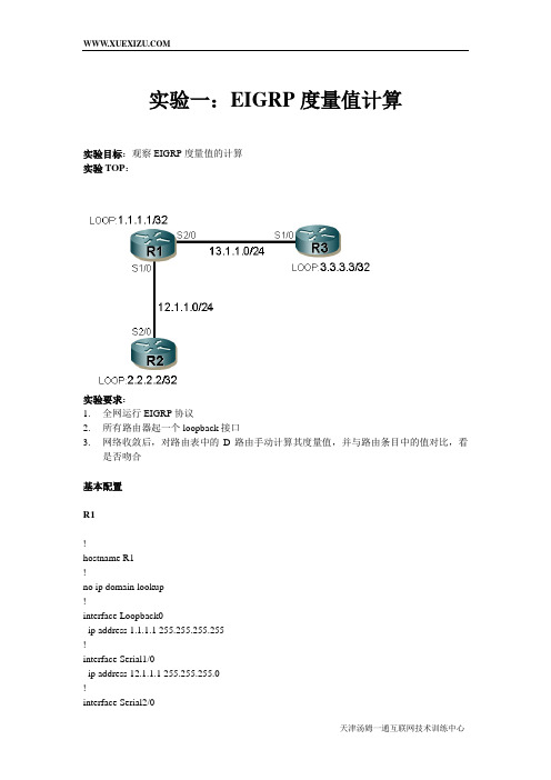
实验一:EIGRP度量值计算(参考配置)
Gateway of last resort is not set
1.0.0.0/32 is subnetted, 1 subnets
C1.1.1.1 is directly connected, Loopback0
2.0.0.0/32 is subnetted, 1 subnets
D2.2.2.2 [90/2297856] via 12.1.1.2, 00:07:38, Serial1/0
Last clearing of "show interface" counters 01:08:06
Input queue: 0/75/0/0 (size/max/drops/flushes); Total output drops: 0
EIGRP的介绍

EIGRP的介绍EIGRP是一种增强的距离矢量路由协议,同时含有距离矢量路由协议(如rip)和链路状态路由协议(如ospf)的特点。
适用于中、大型网络。
是一种cisco私有路由协议,不支持其他厂商设备。
EIGRP的特征有:增量更新;快速汇聚;支持多种网络层协议(IPV4、IPV6、IPX、AppleTalk);使用单播和多播(多播地址为:224.0.0.10);支持VLSM;支持自动汇总,以及支持在网络中任意位置进行手工汇总;支持等价负载均衡、非等价负载均衡;支持多种路由:内部路由、外部路由和汇总路由;精密的度量值:带宽、延迟、可靠性、负载、MTU(缺省时:带宽、负载); 100%无环的无类路由协议(依据DUAL算法中FC(即AD<最优路由的FD)),。
EIGEP邻居建立的条件:两路由器直连,且直连接口IP处于同一网段;两路由器AS号一致;接口若有认证,认证密钥要一致;metric值一致(K值一致);EIGRP工作原理:即:i、运行EIGRP的路由器通过交互hello包建立邻居关系ii、邻居之间通过交互update交换路由信息保存到拓扑数据库iii、从拓扑表中选择最优的路由提交给IP路由表当链路发生变化时,如去往一个目的IP的路由挂掉,则路由器将从拓扑表中查询是否有FS(可行继任者),若有,则提交给IP路由表变成S(继任者);若没有,则依据DUAL算法会向所有邻居路由器查询。
注:i.不符合FC可行性条件的路由为不可用路由,不写入拓扑表中ii.缺省时,拓扑表中去往同一个网络的FS最多只有4条,通过配置最多可有16条iii.将去往某个目标网络的度量值设置为-1时,表示不可达iiii.不同metric值的多条明细路由汇总后,汇总路由的metric值等于明细路由中最小的metric值ERGRP的实验:实验一:(EIGRP邻居建立过程)1)使用debug eigrp packet命令观察EIGRP邻居建立过程2)使用show ip eigrp neighbors [detail]查看EIGRP邻居实验结果:debug eigrp packetshow ip eigrp neighbors [detail]其中,Address:邻居路由器与本路由器直连接口ip;Interface:邻居路由器与本路由器直连接口Hold:保持间隔Uptime:运行时间SRTT:平均往返时间(可靠分组发送到接收ack确认之间的时间)STO:超时时间,重传队列中的分组重传给邻居之前所等待的时间,RTO=6*SRTT.不足200ms按200msQ cnt:等待重传的个数,正常=0Seq num:序列号实验二:(EIGRP自动汇总及手工汇总)实验结果:i.当自动汇总没关闭时,R1、R2的路由表信息为:R1:R2:注意:画红线处是一条指向null 0 的20.0.0.0网段的汇总路由,它是由于对端接口ip进行汇总,所以学习到这条汇总路由。
帧中继下的EIGRP水平分割解决方案实验

帧中继下的EIGRP水平分割解决方案实验来源: 作者:小飞侠发布时间:2008-10-14 阅读次数亚威岁末大优惠——所有Cisco培训课程7折实验步骤:1:在R1上的配置;Router>Router#enRouter#conf tEnter configuration commands, one per line. End with CNTL/Z. Router(config)#no ip domain-loRouter(config)#lin co 0Router(config-line)#logg sRouter(config-line)#no exec-tRouter(config-line)#ho R1R1(config)#int s3/0R1(config-if)#en frR1(config-if)#no frame-relay inverse-arpR1(config-if)#no shuR1(config-if)exitR1(config)#int s3/0.1 multipointR1(config-subif)#no frame-relay inverse-arpR1(config-subif)#ip add 192.168.123.1 255.255.255.0R1(config-subif)#no shuR1(config-subif)#frame-relay map ip 192.168.123.2 102 bR1(config-subif)#frame-relay map ip 192.168.123.3 103 bR1(config-subif)#exitR1(config)#int lo 0R1(config-if)#ip add 1.1.1.1 255.255.255.0R1(config-if)#no shuR1(config-if)#end2:在R2上的配置;Router>enRouter#conf tEnter configuration commands, one per line. End with CNTL/Z. Router(config)#no ip doRouter(config)#no ip domain-loRouter(config)#lin co 0Router(config-line)#logg sRouter(config-line)#no exec-tRouter(config-line)#ho R2R2(config)#int s3/0R2(config-if)no shuR2(config-if)#en frameR2(config-if)#no frame-relay invR2(config-if)#ip add 192.168.123.2 255.255.255.0R2(config-if)#frame map ip 192.168.123.1 201 bR2(config-if)#exitR2(config)#int lo 0R2(config-if)#ip add 2.2.2.2 255.255.255.0R2(config-if)#exitR2(config)#router eigrp 1R2(config-router)#net 192.168.123.0R2(config-router)#net 2.2.2.2R2(config-router)#no auto-summaryR2(config-router)#end3:在R3上的配置;Router>enRouter#conf tEnter configuration commands, one per line. End with CNTL/Z. Router(config)#no ip doRouter(config)#no ip domain-loRouter(config)#lin co 0Router(config-line)#logg sRouter(config-line)#no exec-tRouter(config-line)#ho R3R3(config)#int s3/0R3(config-if)#en frameR3(config-if)#no frame invR3(config-if)#ip add 192.168.123.3 255.255.255.0R3(config-if)#fram map ip 192.168.123.1 301 bR3(config-if)#no shuR3(config-if)#exitR3(config)#int lo 0R3(config-if)#ip add 3.3.3.3 255.255.255.0R3(config-if)#no shuR3(config-if)#exitR3(config)#router eigrp 1R3(config-router)#net 192.168.123.0R3(config-router)#net 3.3.3.3R3(config-router)#no auto-summaryR3(config-router)#end4:在R1上查看路由信息;R1#sho ip routeCodes: C - connected, S - static, I - IGRP, R - RIP, M - mobile, B - BGPD - EIGRP, EX - EIGRP external, O - OSPF, IA - OSPF inter areaN1 - OSPF NSSA external type 1, N2 - OSPF NSSA external type 2 E1 - OSPF external type 1, E2 - OSPF external type 2, E - EGPi - IS-IS, L1 - IS-IS level-1, L2 - IS-IS level-2, ia - IS-IS inter area* - candidate default, U - per-user static route, o - ODRP - periodic downloaded static routeGateway of last resort is not setC 192.168.123.0/24 is directly connected, Serial3/0.11.0.0.0/8 is variably subnetted, 2 subnets, 2 masksD 1.0.0.0/8 is a summary, 00:01:33, Null0C 1.1.1.0/24 is directly connected, Loopback02.0.0.0/24 is subnetted, 1 subnetsD 2.2.2.0 [90/2297856] via 192.168.123.2, 00:01:28, Serial3/0.13.0.0.0/24 is subnetted, 1 subnetsD 3.3.3.0 [90/2297856] via 192.168.123.3, 00:00:59, Serial3/0.1 5:在R2上查看路由信息;R2#sho ip routeCodes: C - connected, S - static, I - IGRP, R - RIP, M - mobile, B - BGPD - EIGRP, EX - EIGRP external, O - OSPF, IA - OSPF inter areaN1 - OSPF NSSA external type 1, N2 - OSPF NSSA external type 2 E1 - OSPF external type 1, E2 - OSPF external type 2, E - EGPi - IS-IS, L1 - IS-IS level-1, L2 - IS-IS level-2, ia - IS-IS inter area* - candidate default, U - per-user static route, o - ODRP - periodic downloaded static routeGateway of last resort is not set6:在R3上查看路由信息;R3#sho ip routeCodes: C - connected, S - static, I - IGRP, R - RIP, M - mobile, B - BGPD - EIGRP, EX - EIGRP external, O - OSPF, IA - OSPF inter areaN1 - OSPF NSSA external type 1, N2 - OSPF NSSA external type 2 E1 - OSPF external type 1, E2 - OSPF external type 2, E - EGPi - IS-IS, L1 - IS-IS level-1, L2 - IS-IS level-2, ia - IS-IS inter area* - candidate default, U - per-user static route, o - ODRP - periodic downloaded static routeGateway of last resort is not set出现的问题:由于水平分割的存在,使得R2和R3之间不可以相互学习路由。
EIGRP实验

D10.0.0ቤተ መጻሕፍቲ ባይዱ0/8 [90/2297856] via 172.16.1.1, 00:10:10, Serial1/0
D 192.168.0.0/24 [90/2297856] via 172.16.1.6, 00:08:14, Serial1/1
R1(config-router)#exit
R1(config)#
随后在R2上观察路由表的变化,如下显示:
R2#show ip route eigrp
172.16.0.0/16 is variably subnetted, 3 subnets, 2 masks
D 172.16.0.0/16 is a summary, 00:07:26, Null0
Sending 5, 100-byte ICMP Echos to 192.168.1.1, timeout is 2 seconds:
.!!!!
Success rate is 80 percent (4/5), round-trip min/avg/max = 4/43/92 ms
R2#
6、路由器R2作为企业的出口路由器,由于其配置了静态路由,因此其可以直接访问外部,但是内部的R1和R5路由器由于缺少路由,因此无法访问外网。下面显示了R1路由器的路由表和其向外部发起ping的访问结果:
R2#
7、我们注意到在R2路由器上有一条指向s1/0口的10.0.0.0/8的汇总路由,这是EIGRP路由协议自动汇总的特性体现。可以使用no auto-summary命令关闭。如下:
R1(config)
EIGRP实验
EIGRP基本配置实验1.实验拓扑:2.实验需求:按照上述拓扑图配置,全网运行EIGRP路由协议,要求R4环回口4.4.4.4/24能够ping通R1 环回口1.1.1.1/24。
3.实验步骤:(1)R4、R2、R1上配置基本IP地址,能够满足直连链路互通。
R4(config)#interface loopback 0R4(config-if)#ip address 4.4.4.4 255.255.255.0R4(config-if)#no shutdownR4(config)#interface serial 1R4(config-if)#ip address 24.0.0.4 255.255.255.0R4(config-if)#no shutdownR2(config)#interface serial 1R2(config-if)#ip address 24.0.0.2 255.255.255.0R2(config-if)#no shutdownR2(config-if)#clock rate 64000R2(config)#interface serial 0R2(config-if)#ip address 12.0.0.2 255.255.255.0R2(config-if)#no shutdownR2(config-if)#clock rate 64000R1(config)#int loopback 0R1(config-if)#ip address 1.1.1.1 255.255.255.0R1(config)#int serial 0R1(config-if)#ip address 12.0.0.1 255.255.255.0R1(config-if)#no shutdown(2)在R4 、R2、R1上运行EIGRP路由协议,并且发布直连网段。
R4(config)#router eigrp 100 //启用EIGRP路由协议,AS号为100对于EIGRP AS号的解释:AS称为自治系统,对于EIGRP,在EIGRP上启用是必须跟AS号,如果AS号不同,路由器会认为两台路由器运行在不同的AS上,所以不能形成邻居关系。
CCNA 实验题 EIGRP排错 对照翻译
1. EIGRPQuestion:After adding BLD-102 router, no routing updates are being exchanged between BLD-102 and the new location. All other inter connectivity and Internet access for the existing locations of the company are working properly.The task is to identify the fault(s) and correct the router configuration to provide full connectivity between the routers.Access to the router CLI can be gained by clicking on the appropriate host. All passwords on all routers are cisco.IP addresses are listed in the chart below.注意:考试时,点路由连接的console(虚线)进入配置进入路由BLD-102BLD-102>enable(密码cisco)BLD-102#show run…………(查看错误,是AS号错或者网段宣告错误)AS号错:BLD-102#configure terminal(conf t)进入全局BLD-102(config)#no router eigrp 22 删掉eigrpBLD-102(config)#router eigrp 212 重新添加eigrpBLD-102(config-router)#network 192.168.22.0 重新宣告网段BLD-102(config-router)#network 192.168.60.0BLD-102(config-router)#no auto-summary 不要忘记关闭自动汇总BLD-102(config-router)#endBLD-102#copy running-config startup-config 不要忘记保存(配置完成后,可以再通过show run 查看一下是否配置成功)宣告错误:BLD-102#configure terminal(conf t)进入全局BLD-102(config)#router eigrp 212 进入eigrp212BLD-102(config-router)#no network 192.168.22.0 删除多余的网段BLD-102(config-router)#network 192.168.60.0 添加网段BLD-102(config-router)#endBLD-102#copy running-config startup-config 不要忘记保存(配置完成后,可以再通过show run 查看一下是否配置成功)。
EIGRP
1.如图所示,将所有直连接口和环回口宣告进EIGRP,观察各路由器学习到的路由情况2.验证EIGRP邻居关系建立的几个必要条件a.K-valueb.AS Numberc.Secondary address(注意观察单边邻居关系,以及EIGRP的重传机制,理解SRTT和Multicast-flow timer/RTO的关系)d.单播和组播发送方式3.通过手工计算R3环回口在R1上显示的Metric,验证EIGRP Metric计算公式4.如图所示,将所有串口和环回口宣告进EIGRP(以太口暂时不宣告),关闭自动汇总,使用4种方法在R3上发布默认路由a.静态默认关联直连接口+network 0.0.0.0b.静态路由关联下一跳+重分布c.汇总发布默认d.Default-network 宣告主类路由发布默认e.最后实验default-information 在EIGRP中的作用5.在R1上添加环回口lo1~lo4 172.16.4.1/24~172.16.7.1/24,在接口下精确汇总发布一条汇总路由a.思考R1自身形成的一条指向null0路由的用处b.R1,R2,R3上开启自动汇总,观察自动汇总和手工汇总的优先级c.R1、R3上关闭自动汇总,在R1上观察R3和R2的环回口路由的区别,思考产生的原因6.将R1/R3的以太口宣告进EIGRP,观察1.1.12./24网段,计算通过Successor和Feasible Successor分别的METRIC,体会差异产生的原因a.通过调整delay,使得R3上看到1.1.12.0/24负载均衡b.还原delay,通过offset-list 列表使得这条路由负载均衡7.还原,通过调整参数,使得1.1.12.0/24路由可以实现不等价负载均衡。
使用ping + repeat ,观察R3通过2条路径发包的现象,思考不等价负载均衡实施负载的方式。
再通过一条命令,使得EIGRP在不等价负载均衡的情况下,始终通过Metric值比较小的一条路径发包,通过ping包验证这一点(注意关闭ipcef)EIGRP分解实验三8.实验EIGRP 跨路由器建立邻居关系:a.R2上no EIGRP进程b.静态路由先让R1 R3之间互相ping通,R1 R3单播互指邻居,注意出现的提示信息,分析产生的原因c.将R1 R3接口地址修改为/16,观察收到路由情况,并分析ping相互收到的路由能否Ping通9.如图所示,将所有串口和环回口宣告进EIGRP,在R1 R2 R3上开启debug eigrp packets query reply ack然后Shut down R1 LO0口,观察各路由器的query包,reply包的发送和确认情况,理解DUAL的扩散查询行为10.通过在R2上S1/1口设置ACL,阻止R3过来的所有EIGRP包,通过设置hold-down time到最长,使它们之间邻居关系保持不DOWN,然后shut down R1 LO0 口,观察EIGRP的拓扑表,学习EIGRP的SIA状态,以及cisco设计SIA-QUERY/SIA-REPLY两种报文的意义11.实验解决SIA的方法一,设定ACTIVE-TIME时间;方法二,汇总路由12.实验EIGRP的STUB路由器,理解STUB的几个选项的意义a.将R3设置成STUB receive-only, R1上观察R3的环回口路由b.在R3上增加一条静态路由33.3.3.0 指向null0, 通过重分布发布进EIGRP,观察stub redistributed/static的行为c.还原,将R2设置成stub,使用ACL/route-map 匹配1.1.1.0/24,观察stub leek-map选项的行为13.在R1 R2之间开启EIGRP 的认证14.在R1上使用distance 255的方法过滤33.3.3.0/24,观察实验现象,理解没有生效的原因15.在R3上使用distribute-list 过滤这条33.3.3.0/24,使之在R1上不可见,但是不能使用基于接口的过滤。
bgp综合实验总结
——————————————袁月BGP综合实验1拓扑图拓扑说明:如图,有R1-R5五台路由器R1,R3,R4的S0/0、S0/1、S0/2口通过FR连接,R1为hub,帧中继链路ip为10.10.134.0/24R1,R2的F1/0口通过以太网连接,链路ip为10.10.12.0/24R4,R5的s0/1口直连,网段10.10.45.0/24每台路由器的环回0口ip为x.x.x.x/32R1上有lo1-lo5,ip地址为192.168.1.1/24---192.168.5.1/24R5上有lo1-lo5,ip地址为172.16.1.1/24---172.16.5.1/24实验要求:1.配置底层:配置每台设备的接口ip,配置完成后确保直连可达每个路由器的环回口是X.X.X.X/322.配置IGP全网运行OSPF area0,仅宣告lo0口和链路ip进入ospf,NBMA区域任意处理3.建立BGP邻居BGP AS区域划分如图,按照如下规则建立对等关系.使用回环口建立邻居.R1 peer R2R2 peer R1,R3R3 peer R2,R4R4 peer R5R5 peer R44.BGP 路由宣告邻居建立完成后,将R1和R5的lo0口宣告进入BGP,使用network命令要求R1,R5使用适当的方式宣告各自的lo1-lo5宣告完成后要求每台设备的bgp转发表可见这些路由5.BGP路由控制要求做出适当控制,达成下列条件,具体方法不限1、使下列条目出现在R1的bgp表中*> 172.16.1.0/24 2.2.2.2 100 0 255 2 3 i*> 172.16.2.0/24 2.2.2.2 255 10 20 2 3 ? *> 172.16.3.0/24 2.2.2.2 0 2 3 i*> 172.16.4.0/24 2.2.2.2 255 2 3 i*> 172.16.5.0/24 2.2.2.2 100 0 255 2 3 i2、使下列条目出现在R5的bgp表中*> 192.168.0.0/21 0.0.0.0 100 32768 2 1 i *> 192.168.1.0 4.4.4.4 0 2 1 i *> 192.168.2.0 4.4.4.4 0 2 1 is> 192.168.3.0 4.4.4.4 0 2 1 is> 192.168.4.0 4.4.4.4 0 2 1 i *> 192.168.5.0 4.4.4.4 0 2 1 i3、完成后,R1,R5互相可PING通对方宣告的这些bgp路由实验效果:R1上查看BGP表R5上查看BGP表BGP综合实验2拓扑图实验要求如下:1 R1与R2为EBGP R2与R3、R4为EBGP R3与R4为IBGP R3与R4、R5为EBGP每台路由器都有X.X.X.XX/32作为router-id 全网底层跑EIGRP 1002 R3、R4学到R1上的bgp路由下一跳必须为AS100的,R5上学到的R1和R3的路由,优走R33 在R1和R5上的回环口分别是20.20.20.0/24和30.30.30.0/24,都重分布到BGP中,使其相互学到并互相连通!实验效果:R3和R4上查看BGP表R5上查看路由表R1和R5上的lo0互相ping通BGP综合实验3拓扑图实验要求如下:1 R4上有192.168.1.0/24、192.168.2.0/24、192.168.3.0/24、192.168.4.0/24和100.100.100.0/24网段,R5上有172.16.1.0/24、172.16.2.0/24、172.16.3.0/24、172.16.4.0/24和50.50.50.1/32网段2 R1为DR,R2和R3不参与DR选举每台路由器都有x.x.x.x/24做为router-id3 Ospf学到的是192.168汇总和172.16的汇总以及100.100的明细路由4 EIGRP不能学到192.168的路由,能学到100.100的路由5 R4为AS100R2为AS200R5为AS300R4只与R2建立EBGP,R5只与R2建立EBGP,R4能学到50.50.50.1/32的路由,且可达!。