二硫化钼电沉积suppt
《二硫化钼复合材料的合成及其光催化和储锂性能研究》

《二硫化钼复合材料的合成及其光催化和储锂性能研究》一、引言随着科技的发展,新型复合材料在光催化与能源存储领域的应用越来越广泛。
二硫化钼(MoS2)作为一种典型的二维过渡金属硫化物,因其独特的物理和化学性质,被广泛应用于光催化与储锂等研究中。
然而,其实际应用中的性能往往受限于单一的MoS2结构,因此通过与其他材料复合以提高其性能成为了研究的新方向。
本文以二硫化钼复合材料的合成为基础,探讨了其光催化和储锂性能的研究。
二、二硫化钼复合材料的合成二硫化钼复合材料的合成方法主要分为物理法和化学法。
物理法包括机械研磨、层间插层等;化学法包括化学气相沉积、溶胶凝胶法等。
本文采用溶胶凝胶法进行合成。
溶胶凝胶法是通过在溶液中加入前驱体,经过一系列化学反应生成溶胶,再经过凝胶化、干燥、热处理等步骤得到复合材料。
在合成二硫化钼复合材料时,我们选择与石墨烯等材料进行复合,以提高其光催化与储锂性能。
三、光催化性能研究二硫化钼复合材料因其特殊的层状结构和电子能带结构,具有良好的光催化性能。
我们通过实验研究了不同比例的二硫化钼与其他材料的复合对光催化性能的影响。
实验结果表明,当二硫化钼与其他材料以一定比例复合时,其光催化性能得到显著提高。
这主要归因于复合材料中各组分之间的协同效应,使得光生电子和空穴的分离效率提高,从而提高了光催化效率。
此外,我们还研究了不同光源、不同pH值等条件对光催化性能的影响,为实际应用提供了理论依据。
四、储锂性能研究二硫化钼复合材料因其高比表面积和良好的导电性,被认为是一种具有潜力的锂离子电池负极材料。
我们通过实验研究了二硫化钼复合材料的储锂性能。
实验结果表明,二硫化钼复合材料具有较高的可逆容量和较好的循环稳定性。
在充放电过程中,其具有良好的嵌锂/脱锂能力,表现出较高的库伦效率和良好的容量保持率。
此外,我们还研究了不同合成方法、不同复合比例等因素对储锂性能的影响,为进一步优化材料提供了方向。
五、结论本文以二硫化钼复合材料的合成为基础,通过实验研究了其光催化和储锂性能。
电沉积法制备钼涂层的探讨

电沉积法制备钼涂层的探讨电沉积法制备钼涂层的探讨电沉积法是一种将金属离子通过电化学反应沉积在基体表面的方法。
下面将逐步讨论使用电沉积法制备钼涂层的步骤。
第一步是准备工作。
首先,需要准备好电沉积设备,包括电解槽、电源和电极。
其次,需要准备好钼离子溶液,这可以通过将钼粉溶解在适当的溶剂中制备而成。
最后,准备基体,确保其表面清洁并且没有杂质,以便钼涂层能够均匀附着。
第二步是电解槽的装配。
将电解槽填满钼离子溶液,并将基体放置在电解槽中,确保基体与电极之间有适当的间距。
第三步是设定电流密度和电沉积时间。
根据所需的钼涂层厚度和质量,设定适当的电流密度和电沉积时间。
电流密度是指单位面积上通过的电流量,可以通过调整电源的电流设置。
电沉积时间是指将电流施加于基体上的时间,可以通过控制电源的时间设定。
第四步是进行电沉积过程。
将电源连接到电解槽中的电极上,并打开电源。
通过电化学反应,钼离子会被还原成钼金属,并沉积在基体表面上,形成钼涂层。
第五步是涂层的处理和表征。
在完成电沉积过程后,取出基体并对钼涂层进行处理,例如清洗和干燥。
可以使用扫描电子显微镜(SEM)等工具来表征涂层的微观形貌和厚度。
最后,进行涂层性能的评估。
可以使用各种表征技术,如硬度测试、耐腐蚀性能测试等,对钼涂层的性能进行评估。
综上所述,根据电沉积法制备钼涂层的步骤包括准备工作、电解槽的装配、设定电流密度和电沉积时间、进行电沉积过程、涂层的处理和表征以及涂层性能的评估。
通过这些步骤,可以制备出具有特定厚度和质量的钼涂层,用于不同的应用领域。
二硫化钼-石墨烯复合材料制备及其电化学性能研究

二硫化钼-石墨烯复合材料制备及其电化学性能探究二硫化钼/石墨烯复合材料制备及其电化学性能探究摘要:二硫化钼/石墨烯复合材料因其奇特的结构和优异的性能,在电化学领域引起了广泛的探究爱好。
本文以石墨烯为载体,通过化学气相沉积法制备了二硫化钼/石墨烯复合材料,并对其电化学性能进行了探究。
结果表明,二硫化钼/石墨烯复合材料具有优异的电化学性能,可作为超级电容器、锂离子电池等能量储存和转化器件的抱负材料。
引言:随着能源危机和环境污染问题的日益加剧,新型的高性能电化学能源储存器件得到了广泛的探究。
二硫化钼( MoS2 ) 作为一种典型的层状过渡金属硫化物,具有优异的物理和化学性能,被广泛应用于电化学储能领域。
然而,MoS2 的电导率较低,对电化学性能的提升有一定的限制。
为了克服这一问题,石墨烯被引入到MoS2 中,形成二硫化钼/石墨烯复合材料,以提高其电导率和电化学性能。
试验部分:1. 试验材料与仪器本试验所使用的材料包括二硫化钼纳米粉末、石墨烯氧化物纳米片以及乙醇等,试验仪器包括扫描电子显微镜(SEM)、透射电子显微镜(TEM)、电化学工作站等。
2. 二硫化钼/石墨烯复合材料的制备起首制备石墨烯氧化物纳米片,将石墨烯氧化物纳米片与二硫化钼纳米粉末混合,并在惰性气氛下进行高温还原,最后得到二硫化钼/石墨烯复合材料。
结果与谈论:通过SEM和TEM观察,可以看到制备得到的二硫化钼/石墨烯复合材料呈现出层状结构,并且石墨烯片层与二硫化钼纳米粉末之间有良好的结合。
这种结构为复合材料的电化学性能提供了良好的导电通道,并增加了电极与电解质之间的接触面积。
进一步的电化学性能测试表明,二硫化钼/石墨烯复合材料在循环伏安曲线和恒流充放电测试中呈现出优异的性能。
其具有较高的比电容和循环稳定性,表明其具有较好的能量储存和转化性能。
同时,该复合材料还具有快速充放电反应速度和良好的电化学活性,能够在短时间内实现高效能量输出。
结论:本文成功制备了二硫化钼/石墨烯复合材料,并对其电化学性能进行了探究。
电沉积法制备钼涂层的解析

电沉积法制备钼涂层的解析电沉积法制备钼涂层的解析电沉积法是一种制备金属涂层的常用方法,其中制备钼涂层的步骤如下:1. 准备实验设备和材料:首先,准备一个电沉积设备,包括电源、电解槽、电极等。
同时,需要购买钼盐溶液作为电沉积液,以及钼板作为电极材料。
2. 准备钼盐溶液:将一定量的钼盐加入适量的溶剂中,例如水或有机溶剂,制备成钼盐溶液。
可以根据需要调整溶液的浓度,以控制钼涂层的质量和厚度。
3. 准备电解槽和电极:将电解槽中填充好钼盐溶液,并将钼板作为阳极或阴极放置在电解槽中。
根据要求选择不同的电解槽和电极组合方式,以确保电沉积过程的稳定性和效果。
4. 调整电流和时间:通过调整电源的电流和电解槽中的电解时间,控制钼涂层的生长速率和厚度。
通常,较高的电流和较长的电解时间会导致更厚的涂层,而较低的电流和较短的电解时间则会产生较薄的涂层。
5. 开始电沉积:打开电源,使电流通过电解槽和电极,开始电沉积过程。
在电解槽中,钼离子会在电极表面还原为钼金属,并沉积在电极上形成钼涂层。
电沉积过程中需要注意控制温度、搅拌速度等参数,以保证涂层的均匀性和质量。
6. 结束电沉积:根据需要,调整电沉积的时间,使得钼涂层达到所需的厚度。
然后,关闭电源,结束电沉积过程。
7. 清洗和处理涂层:将电极从电解槽中取出,用水或其他溶剂清洗涂层,去除可能存在的杂质和溶剂残留。
如果需要,可以对涂层进行后续处理,如热处理、电化学处理等,以改善涂层的性能和质量。
通过以上步骤,我们可以使用电沉积法制备出所需的钼涂层。
这种方法简单易行,操作方便,可以用于制备各种金属涂层,具有广泛的应用潜力。
二硫化钼及其复合材料的制备与应用

二硫化钼及其复合材料的制备与应用二硫化钼(MoS2)是一种常见的二维材料,具有广泛的应用前景。
制备和应用技术的研究对于开发其潜在的应用具有重要意义。
本文将讨论关于二硫化钼及其复合材料制备和应用的相关内容。
谈到了二硫化钼的制备方法。
传统的制备方法主要包括化学气相沉积(CVD)、气体相硫化法、机械合成法、水热法等。
CVD是一种常用的方法,通过在高温下将金属硫化物分子在基底上分解沉积,形成二硫化钼薄膜。
机械合成法则是将金属硫化物与硫反应,通过机械装置将其研磨并制成纳米颗粒。
水热法则是利用水热反应条件,在高温高压下将硫与金属离子(如钼离子)反应生成纳米级的二硫化钼颗粒。
介绍了二硫化钼复合材料的制备方法。
二硫化钼复合材料的制备通常涉及将二硫化钼与其他材料进行复合。
常见的复合材料包括二硫化钼/石墨烯复合材料、二硫化钼/多壁碳纳米管复合材料等。
这些复合材料的制备方法一般包括物理混合法、化学沉积法、电化学沉积法等。
制备二硫化钼/石墨烯复合材料时,可以通过机械混合法将二硫化钼颗粒与石墨烯颗粒混合,然后用化学还原法将其还原成复合材料。
然后,探讨了二硫化钼及其复合材料的应用。
由于其独特的物理和化学性质,二硫化钼及其复合材料在电子器件、光电器件、催化剂、传感器、润滑剂等领域具有广泛的应用。
二硫化钼薄膜可以作为电子器件中的场效应晶体管(FET)的通道材料,用于制备高性能的电子器件。
二硫化钼/石墨烯复合材料可以用于制备高性能的电池电极材料,提高电池的能量存储性能。
二硫化钼复合材料还可以用作催化剂,在化学反应中起到催化作用。
层状二硫化钼纳米复合材料在超级电容器中的应用
层状二硫化钼纳米复合材料在超级电容器中的应用超级电容器(supercapacitor)是一种高性能储能装置,具有高能量密度和高功率密度的特点,被广泛应用于电子设备、交通工具和可再生能源储存等领域。
然而,传统的超级电容器在电能存储密度和循环寿命方面仍存在挑战。
因此,寻找一种具有较高储能密度和较长循环寿命的电极材料对于超级电容器的发展至关重要。
近年来,层状二硫化钼纳米复合材料受到了研究人员的广泛关注。
层状二硫化钼(MoS2)是一种二维结构的材料,具有优异的化学稳定性和电化学活性。
通过将MoS2与其他导电材料(如碳纳米管、石墨烯等)复合,可以实现对电容器性能的进一步优化。
层状二硫化钼纳米复合材料具有许多优越的特性,使其成为超级电容器的有力候选材料。
首先,由于层状结构和大表面积,MoS2可以提供更大的电荷存储空间,从而提高电容量和储能密度。
其次,MoS2具有优异的电导率和快速离子迁移速度,使得层状二硫化钼纳米复合材料具有较高的功率密度。
此外,MoS2表面的大量反应活性位点可以促进电极材料与电解质之间的电荷传递和离子传输,从而提高超级电容器的循环稳定性和寿命。
在超级电容器的应用中,层状二硫化钼纳米复合材料的制备方法和结构调控对于性能的改善至关重要。
研究表明,采用多步法制备的层状二硫化钼纳米复合材料具有更好的电容性能。
一种常见的方法是通过溶液浸渍、电沉积或晶体生长等方法将MoS2与导电支撑物相结合。
同时,可以通过调控MoS2层状结构的层数、粒径和形貌等参数来优化电容器的性能。
例如,较小的层状结构和较大的比表面积可以提高电荷传递速率和储能密度。
层状二硫化钼纳米复合材料在实际应用中已经取得了一些良好的成果。
研究人员发现,在超级电容器中使用MoS2纳米片和碳纳米管纳米复合电极材料,可以实现高达400 F/g的超高电容量,并且在10000次循环充放电后仍保持90%以上的容量保持率。
此外,层状二硫化钼纳米复合材料还可以与其他材料(如金属氧化物、金属硫化物等)复合,进一步提高超级电容器的性能。
镀液中二硫化钼添加量对镍-二硫化钼复合电镀层耐磨性的影响
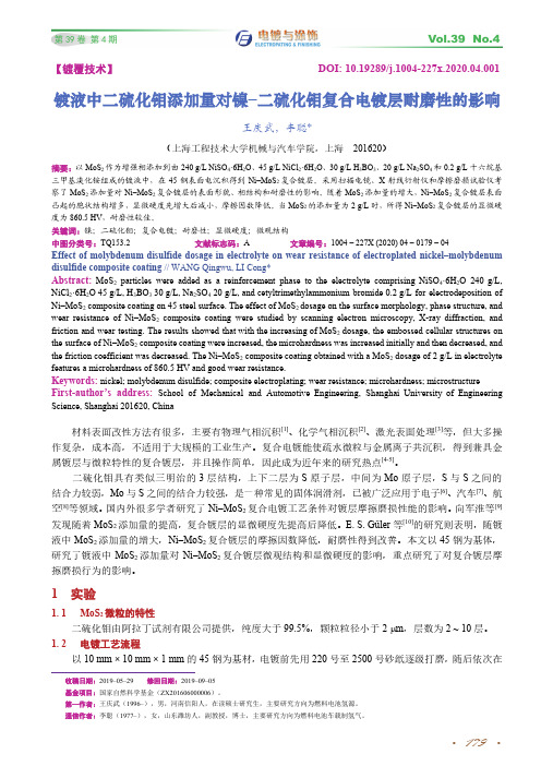
三甲基溴化铵组成的镀液中,在 45 钢表面电沉积得到 Ni–MoS2 复合镀层。采用扫描电镜、X 射线衍射仪和摩擦磨损试验仪考
察了 MoS2 添加量对 Ni–MoS2 复合镀层的表面形貌、相结构和耐磨性的影响。随着 MoS2 添加量的增大,Ni–MoS2 复合镀层表面
凸起的胞状结构增多,显微硬度先增大后减小,摩擦因数降低。当 MoS2 的添加量为 2 g/L 时,所得 Ni–MoS2 复合镀层的显微硬
Science, Shanghai 201620, China
材料表面改性方法有很多,主要有物理气相沉积[1]、化学气相沉积[2]、激光表面处理[3]等,但大多操
作复杂,成本高,不适用于大规模的工业生产。复合电镀能使疏水微粒与金属离子共沉积,得到兼具金 属镀层与微粒特性的复合镀层,并且操作简单,因此成为近年来的研究热点[4-5]。
二硫化钼具有类似三明治的 3 层结构,上下二层为 S 原子层,中间为 Mo 原子层,S 与 S 之间的 结合力较弱,Mo 与 S 之间的结合力较强,是一种常见的固体润滑剂,已被广泛应用于电子[6]、汽车[7]、航 空[8]等领域。国内外很多学者研究了 Ni–MoS2 复合电镀工艺条件对镀层摩擦磨损性能的影响。向军淮等[9] 发现随着 MoS2 添加量的提高,复合镀层的显微硬度先提高后降低。E. S. Güler 等[10]的研究则表明,随镀 液中 MoS2 添加量的增大,Ni–MoS2 复合镀层的摩擦因数降低,耐磨性得到改善。本文以 45 钢为基体, 研究了镀液中 MoS2 添加量对 Ni–MoS2 复合镀层微观结构和显微硬度的影响,重点研究了对复合镀层摩 擦磨损行为的影响。
1 实验
1. 1 MoS2 微粒的特性 二硫化钼由阿拉丁试剂有限公司提供,纯度大于 99.5%,颗粒粒径小于 2 m,层数为 2 ~ 10 层。
化学气相沉积法制备二硫化钼薄膜及电学性能表征

化学气相沉积法制备二硫化钼薄膜及电学性能表征作为一类重要的二维平面半导体材料,二硫化钼(MoS2)薄膜以其独特的物理性能受到广泛关注和深入研究。
因其拥有与石墨烯类似的微观结构、具备较为理想的载流子迁移率以及对段沟道效应近乎免疫等特点,MoS2在多种微电子器件上,如储氢器件、场效应晶体管(MOSFET)以及光电传感器等,都有着很大的应用前景。
本文采用化学气相沉积法(CVD)制备了多种形貌的MoS2薄膜,并对薄膜形貌、结构以及电学特性进行了表征;在此基础上,制备了不同层数、带有背栅或顶栅结构的MOSFET,并对MOSFET的电学性能进行了表征;最后,本文还制备了MoS2基光敏传感器,并对器件性能进行了测试。
具体研究内容如下:(1)对CVD法制备MoS2薄膜的工艺进行了探索。
通过光学显微镜、原子力显微镜、拉曼散射图谱、XRD衍射图谱等手段对MoS2薄膜的微观形貌、结晶质量等进行了表征,研究了不同参数对MoS2薄膜制备的影响,确定了最优工艺条件。
并通过对工艺流程进行改进的方法减少了MoS2中3R亚稳结构的出现,有效的提高了薄膜的结晶质量。
(2)分别选取了CVD法制得的单层或多层MoS2薄膜为沟道材料,制备了具有背栅结构的场效应晶体管(MOSFET),并对MOSFET进行了电学性能测试。
测试结果表明单层MoS2沟道载流子迁移率大小约为0.03±0.01 cm2V-1s-1,而3层MoS2沟道的载流子迁移率大小约为0.6 cmV-1s-1,大于单层MoS2沟道的电子迁移率。
单层或多层MoS2沟道均为N型。
制备了带有顶栅结构的MoS2场MOSFET,并对其电学性能进行了测试。
测试结果表明,引入高K值介电层能有效提高载流子迁移率至4.3 cm2V-1s-1.(3)使用预置图形的方法在带有二氧化硅的硅衬底上制备了条形MoS2薄膜,并将其转移至透明衬底,制备了透明MoS2基光敏传感器,并对传感器的性能进行了测试。
- 1、下载文档前请自行甄别文档内容的完整性,平台不提供额外的编辑、内容补充、找答案等附加服务。
- 2、"仅部分预览"的文档,不可在线预览部分如存在完整性等问题,可反馈申请退款(可完整预览的文档不适用该条件!)。
- 3、如文档侵犯您的权益,请联系客服反馈,我们会尽快为您处理(人工客服工作时间:9:00-18:30)。
Electronic Supplementary InformationAmorphous Molybdenum Sulfide Films as Catalysts for Electrochemical HydrogenProduction in WaterDaniel Merki, Stéphane Fierro, Heron Vrubel, Xile Hu*Laboratory of Inorganic Synthesis and Catalysis, Institute of Chemical Sciences and Engineering, Ecole Polytechnique Fédérale de Lausanne (EPFL), SB-ISIC-LSCI, BCH 3305, Lausanne, CH 1015, Switzerland* To whom correspondence should be addressed. E-mail: xile.hu@epfl.chS1Chemicals and ReagentsAll manipulations were carried out under an inert N2(g) atmosphere using glovebox techniques unless otherwise mentioned. Unless noted, all other reagents were purchased from commercial sources and used without further purification.Physical methodsGC measurement was conducted on a Perkin-Elmer Clarus 400 GC with a FID detector a TCD detector and a 5Å molecular sieves packed column with Ar as a carrier gas. UV-Vis measurements were carried out using a Varian Cary 50 Bio Spectrophotometer controlled by Cary WinUV software. SEM secondary electron (SE) images were taken on a Philips (FEI)XLF-30 FEG scanning electron microscope. XRD measurements were carried out on a PANalytical X'Pert PRO diffractometer using Cu Kα1 radiation (0.1540 nm). Electrochemical measurements were recorded by an IviumStat electrochemical analyzer or an EG&G Princeton Applied Research Potentiostat/Galvanostat model 273. A three-electrode configuration was used. For polarization and electrolysis measurements, a platinum wire was used as the auxiliary electrode and an Ag/AgCl (KCl saturated) electrode was used as the reference electrode. The reference electrode was placed in a position very close to the working electrode with the aid of a Luggin tube. For rotating disk measurements, an Autolab Rotating Disk Electrode assembly was used. Potentials were referenced to reversible hydrogen electrode (RHE) by adding a value of (0.197 + 0.059 pH) V. The polarization curves measured under one atmosphere of H2 are nearly identical to those collected in the absence of external H2, indicating that the potentials measured in the latter experiments are close to the thermodynamically-calibrated values. Ohmic drop correction was done prior to Tafel analysis. Film thickness was measured using an Alpha StepS2500 (KLA-Tencor) stylus-based surface profiler. Pressure measurements during electrolysis were performed using a SensorTechnics BSDX0500D4R differential pressure transducer. Both current and pressure data were recorded simultaneously using an A/D Labjack U12 interface with a sampling interval of one point per second. X-ray photoelectron spectroscopy (XPS) data were collected by Axis Ultra (Kratos analytical, Manchester, UK) under ultra-high vacuum condition (<10-8 Torr), using a monochromatic Al Kα X-ray source (1486.6 eV), in the Surface Analysis Laboratory of CIME at EPFL. The source power was maintained at 150 W (10 mA, 15kV). Gold (Au 4f7/2) and copper (Cu 2p3/2) lines at 84.0 and 932.6 eV, respectively, were used for calibration, and the adventitious carbon 1s peak at 285 eV as an internal standard to compensate for any charging effects. For quantification, relative sensitivity factors from the supplier were used. The XPS samples were placed inside an antechamber which was then evacuated by an independent turbomolecular pump. The inner door of the antechamber was then opened and the samples were introduced to the main chamber of XPS analysis.Deposition of filmsI. On glassy carbon electrodesA 3 mm diameter glassy carbon rotating disk working electrode from Autolab (6.1204.300 GC) and a 3 mm diameter glassy carbon working electrode from CH Instruments (CHI 104) were used.S3The electrodes were polished with two different Alpha alumina powder (1.0 and 0.3 micron fromCH Instruments) suspended in distilled water on a Nylon polishing pad (CH Instruments) and with Gamma alumina powder (0.05 micron from CH Instruments) suspended in distilled water on a Microcloth polishing pad (CH Instruments). Before going to the next smaller powder size and at the end of polishing, the electrodes were thoroughly rinsed with distilled water. Deposition of MoS3-CV: The modification was carried out in a glove box under nitrogen. The freshly polished electrode was immersed into a 2 mM solution of (NH4)2[MoS4] in 0.1 M NaClO4 in water (8 mL). Both chemicals were used as received (Aldrich). Thirty consecutive cyclic voltammograms were carried out on an Ivium Stat potentiostat (Ivium Technologies) with a saturated silver/silver chloride reference electrode (separated by a porous vycor tip) and a titanium wire counter electrode. The cyclic voltammograms were performed between +0.1 and -1.0 V vs. Ag/AgCl (sat.) and a scan rate of 0.05 V/s was employed. Finally, the modified electrode was rinsed with distilled water.II. On FTO-coated glass platesOn FTO-coated glass plates: FTO-coated glass was cut down to rectangular plates of 9 x 25 mm. The plates were cleaned in a bath of 1 M KOH in ethanol and washed with ethanol, water and acetone. An adhesive tape with a hole of 5 mm diameter was attached on each plate in such a way that a circle of 5 mm diameter in the bottom part and a small strip at the top of the plate remained uncovered. The plate will be modified in the area of the circle only and the uncovered strip serves as electrical contact.Depositions of MoS3-CV: The modification was carried out in a glove box under nitrogen. Thefreshly prepared FTO electrode was immersed into a 2 mM solution of (NH4)2[MoS4] in 0.1 MS4NaClO4 in water (6 mL). Both chemicals were used as received (Aldrich). Fifteen, twenty-five or thirty-five consecutive cyclic voltammograms were carried out on an Ivium Stat potentiostat (Ivium Technologies) with a saturated silver/silver chloride reference electrode (separated by a porous vycor tip) and a platinum wire counter electrode. The cyclic voltammograms were performed between +0.1 and -1.0 V vs. Ag/AgCl (sat.) and a scan rate of 0.05 V/s was employed. Finally, the modified electrode was rinsed with distilled water.Note: to ensure that the catalytic properties of the MoS3-CV films are not due to Pt particles that can be accidently deposited during film formation, we also deposited MoS3-CV films using Ti as the counter electrode. The polarization curves of these films were measured using Ti as the counter electrode as well. At overpotentials below 300 mV, the polarization curves are nearly identical to those measured using Pt as the counter electrode. Some discrepancy was found at higher overpotentials, probably because the Ti counter electrode is not able to supply enough current at those potentials. These results rule out the possibility of Pt contamination. Deposition of MoS2-CV film: Same procedure as described for MoS3-CV film, but the cyclic voltammograms were performed between -1.0 and +0.1 V vs. Ag/AgCl (sat.), i.e. they started and ended at -1.0 V vs. Ag/AgCl (sat.).Deposition of MoS3-AE: Same conditions as described above, but instead of consecutive cyclic voltammograms, a constant potential of +0.3 V vs. Ag/AgCl (sat.) was applied for 70 s. Deposition of MoS2-CE film: Same conditions as described above, but instead of consecutive cyclic voltammograms, a constant potential of -1.3 V vs. Ag/AgCl (sat.) was applied for 160 s.S5Ohmic drop correction:The ohmic drop correction of polarization curves has been performed according to the method given in the literature [1-3]. The overpotential η (V) observed during an experiment is given by equation (1):η=a+bln j+jR (1)where a (V) is the Tafel constant, b (V dec-1) is the Tafel slope, j (A cm-2) is the current density and R (Ω cm-2) is the total area-specific uncompensated resistance of the system, which is assumed to be constant. The derivative of Eq. (1) with respect to current density gives Eq. (2) from which b and R can be easily obtained by plotting dη/dj as a function of 1/j.dηdj =bj+R (2)The estimation of R allows correcting the experimental overpotential by subtracting the ohmic drop jR according to equation (3):ηcorr=η−jR (3)During the calculations, the derivative dη/dj was replaced by their finite elements Δη/Δj estimated from each pair of consecutive experimental points.Bulk ElectrolysisElectrolysis experiments were performed in an H shape cell (Fig. S1). The platinum counter electrode was separated from the solution through a porous glass frit (porosity 3) and this whole assembly inserted into one side of the H cell. The modified working electrode was inserted in theS6other side of the cell, together with a magnetic stirring bar and a Luggin capillary. Two small inlets were present in the cell allowing the connection to the pressure monitoring device and the other kept closed by a septum for sampling of the gas phase. The whole cell apparatus isgas-tight and the pressure increase is proportional to the gases generated (H2 + O2). It is assumed that for 2 moles of H2 generated in the working electrode, 1 mole of O2 is generated in the counter electrode. Prior to each experiment, the assembled cell was calibrated by injecting known amounts of air into the closed system and recording the pressure change, after the calibration the cell was purged with nitrogen for 20 minutes and the measurements were performed.Control experiments were performed using platinum as a working electrode and a quantitative Faraday yield was obtained by measuring the pressure (97-102 %) and confirmed by GC analysis of the gas in the headspace (92-96 %) at the end of the electrolysis. For the electrochemical modified electrodes the films were deposited on glassy carbon electrodes and electrolysis carried out during 60 minutes. At the end the current efficiency was determined by the pressure change in the system and confirmed by GC analysis.Calculation of active sitesThe MoS3-CV film was deposited as described above during a certain number of consecutive cyclic voltammograms in a solution of (NH4)2MoS4 in pH = 7 phosphate buffer (modification cycles). After 6, 9, 12, 15 and 18 modification cycles, cyclic voltammetry measurements were carried out in pH = 7 phosphate buffer only (blank measurements). The potential window and scan rate applied for these blank measurements were the same as those applied for the modification cycles.S7S8Later, the absolute components of the voltammetric charges (cathodic and anodic) reportedduring one single blank measurement were added. Assuming a one electron redox process, this absolute charge was divided by two. The value was then divided by the Faraday constant to get the number of active sites of the film.Following this procedure, the number of active sites (in mol) after 6, 9, 12, 15 and 18modification cycles was determined.Determination of the turnover frequency (TOF)When the number of active sites is known, the turnover frequencies (in s -1) were calculated with the following equation: 21F TOF n I =I : Current (in A) during the linear sweep measurement after 6, 9, 12, 15 or 18 modification cycles, respectively.F: Faraday constant (in C/mol).n : Number of active sites (in mol) after 6, 9, 12, 15 or 18 modification cycles, respectively.The factor ½ arrives by taking into account that two electrons are required to form one hydrogen molecule from two protons.Reference[1] D.M. Schub, M.F. Reznik, Elektrokhimiya, 21 (1985) 937[2] N. Krstajic, S. Trasatti, Journal of Applied Electrochemistry. 28 (1998) 1291[3] L.A. De Faria, J.F.C. Boodts, S. Trasatti, Journal of Applied Electrochemistry, 26 (1996) 1195A B CDEFig. S1 Cell used for electrolysis experiments. (A) Insert on the Luggin capillary for the reference electrode, (B) 6 mm diameter glassy carbon working electrode, (C) Platinum wire counter electrode, (D) Septum closed inlet, (E) PVC tubing connecting the cell to the pressure meter.S9S1010000200003000040000C PS Binding Energy (eV)238236234232230228226224222Binding Energy (eV)Mo 3d 5/2228.55Mo 3d 3/2231.65BS11174172170168166164162160158156Binding energy (eV)162.3163.5S 2p1/2S 2p3/2CFig. S2 (A) XPS survey spectrum of the MoS 3-CV film. (B) XPS Mo spectrum of commercial MoS 2 particles. The spectrum shows a peak at lower binding energies, which is the S 2s peak. (C) XPS S spectrum of commercial MoS 2 particles. The S/Mo ratio is 2.1 for MoS 2 particle.S12239.8237.6235.4233.2231.0228.8226.6224.4222.2220.0DataMo 3d 5/2 Mo 3d 3/2 EnvelopeBinding Energy (eV)A168166164162160158156Binding Energy (eV)Data S 2- 2p 3/2 S 2- 2p 1/2 S 22- 2p 3/2 S 22-2p 1/2 EnvelopeBS13240238236234232230228226224222220DataMo 3d 5/2 Mo 3d 3/2 EnvelopeBinding Energy (eV)C167.7166.4165.1163.8162.5161.2159.9158.6157.3156.0Data S 2- 3p 3/2 S 2- 3p 1/2 EnvelopeBinding Energy (eV)DFig. S3 (A) XPS Mo spectrum of the MoS 3-AE film. (B) XPS S spectrum of the MoS 3-AE film. (C) XPS Mo spectrum of the MoS 2-CE film. (D) XPS S spectrum of the MoS 2-CE film.S143004005006007008000.00.10.20.30.40.50.60.70.8A b sWavelength (nm)MoS 3-CV film MoS 2-CV film MoS 3-AE film MoS 2-CE filmFig. S4 UV-vis absorption spectra of the freshly prepared MoS x films: MoS 3-CV, MoS 2-CV, MoS 3-AE, and MoS 2-CE.S15-600-500-400-300-200-100-10-8-6-4-22C u r r e n t d e n s i t y (m A /c m 2)mV (vs RHE)pH 7 pH 9 pH 11 pH 13A-300-250-200-150-100-500-4.0-3.5-3.0-2.5-2.0-1.5-1.0-0.50.0C u r r e n t d e n s i t y (m A /c m 2)mV (vs RHE)MoS 3-CV on FTOBS16-500-400-300-200-100-300-250-200-150-100-50C u r r e n t d e n s i t y (m A /c m 2)Potential (mV vs. RHE)C2468-1.0-0.50.00.51.01.52.0l o g JpHFig. S5 (A) Polarization curves of MoS 3-CV film on a rotating glassy carbon electrode recorded at pH = 7, 9, 11, and 13. Scan rate: 2 mV/s; rotating rate: 4500 rpm. (B) Polarization curves of MoS 3-CV film on FTO recorded at pH = 2. Scan rate: 2 mV/s (C) Polarization curve of MoS 3-CV film on a rotating glassy carbon electrode recorded at pH = 0 showing response at a current higher than 100 mA/cm 2. Scan rate: 2 mV/s; rotating rate: 4500 rpm. (D) Dependence of logj over the pH values for MoS 3-CV film at 200 and 300 mV overpotential.S17-0.4-0.3-0.2-0.10.00.10.2-45-40-35-30-25-20-15-10-50C u r r e n t d e n s i t y (m A /c m 2)Potential (V vs. RHE)MoS 3-AE filmscan 2 scan 3 scan 4 scan 5A-0.4-0.3-0.2-0.10.00.10.2-35-30-25-20-15-10-50C u r r e n t d e n s i t y (m A /c m 2)Potential ( V vs. RHE)MoS 3-CV filmscan 2 scan 3 scan 4 scan 5BS18-0.4-0.3-0.2-0.10.00.10.2-50-45-40-35-30-25-20-15-10-50C u r r e n t d e n s i t y (m A /c m 2)Potential (V vs. RHE)MoS 2-CV filmscan 2 scan 3 scan 4 scan 5C-0.4-0.3-0.2-0.10.00.10.2-25-20-15-10-5C u r r e n t d e n s i t y (m A /c m 2)Potential (V vs. RHE)MoS 2-CE filmScan 2 Scan 3 Scan 4 Scan 5DFig. S6 Consecutive polarization curves of MoS x films on FTO at pH = 0: MoS 3-AE (A), MoS 3-CV (B), MoS 2-CV (C), and MoS 2-CE (D).S19240238236234232230228226224222220DataMo 3d 5/2 Mo 3d 3/2 EnvelopeBinding Energy (eV)A168166164162160158156Data S 2- 3p 3/2 S 2- 3p 1/2 EnvelopeBinding Energy (eV)BFig. S7 (A) XPS Mo spectrum of the MoS 3-CV film after 10 polarization measurement at pH = 0. (B) XPS S spectrum of the MoS 3-CV film after 10 polarization measurement at pH = 0.S203004005006007008000.00.20.40.60.8A b sWavelength (nm)MoS 3-CV film MoS 2-CV film MoS 3-AE filmMoS 2-CE filmFig. S8 UV-vis absorption spectra of the MoS x films after 5 polarization cycles: MoS 3-CV, MoS 2-CV, MoS 3-AE, and MoS 2-CE.S21-2.7-2.6-2.5-2.4-2.3-2.2-2.1-2.0-1.9165170175180185190195200205deposition: 25 cycles j 0=1.33 10-7 A/cm240.5 mV per decadeη (m V )log j (log (A/cm 2))Fig. S9 Tafel analysis of the polarization curve at η = 170 to 200 mV for MoS 3-CV film onglassy carbon at pH = 0. The film was made with 25 scanning cycles. Scan rate for polarization: 1 mV/s.S2201020304050600.000.881.762.643.524.40V o l u m e o f H 2 (m L )Time (min)DetectedTheoreticalFig. S10 Current efficiency for H 2 production catalyzed by a MoS 3-CV film on glassy carbon at pH = 0 and 300 mV overpotential. The theoretical line was calculated according to the cumulative charge, assuming a 100% Faraday's yield for H 2 production.Fig. S11 Calculated TOFs for MoS3-CV as a function of potential at pH = 7. The polarization curves were recorded on films deposited on a rotating glassy carbon electrode. Scan rate: 2mV/s; rotating rate: 6000 rpm.S23。