旋流泵设计说明书
螺旋离心泵毕业设计
螺旋离心泵毕业设计【篇一:螺旋离心泵的设计】第一章绪论1.1螺旋离心泵概述泵是把原动机的机械能转换为抽送液体能量的机器。
一般,原动机通过泵轴带动叶轮旋转,对液体做功使其能量增加,从而使要求数量的液体从吸入口通过泵的过流部分,输送到要求的高度或要求有压力的地方。
泵是世界上最早发明的机器之一。
现今世界上泵产品产量仅次于电机,所消耗的电量大约为总发电量的四分之一。
泵的种类甚多,应用极为广泛。
除农田灌溉、城市和工业给排水、热电厂、石油炼厂、石油矿厂、输油管线、化工厂、钢铁厂、采矿、造船等部门外,目前泵在原子能发电、舰艇的喷水推进、火箭的燃料供给等方面亦得到重要应用。
另外,还可以用泵来对固体如煤、鱼等进行长距离水力输送。
泵抽送的介质除水外,有油、酸、碱浆料??一直到超低温的液态气体和高温熔融金属。
可以说,凡是要让液体流动的地方,就有泵在工作。
泵在国民经济中起着十分重要的作用。
根据科学技术的发展,泵输送固态物质的应用领域日益扩大,如污水污物、泥浆、纸浆、灰渣矿石、粮食淀粉、甜菜水果、鱼虾贝壳等不胜枚举。
据文献介绍,如今已成功地从5000米深的海底用泵向陆地输送猛矿石。
对输送这类物质的泵,有两个主要要求:一是无堵塞,二是耐磨损。
耐磨损主要与材料有关,无堵塞主要取决于叶轮的结构形式。
目前作为无堵塞泵叶轮的结构形式有:1.开式或半开式叶轮;2.旋流式叶轮;3.单(双)流道式叶轮;4.螺旋离心叶轮。
螺旋离心泵是典型的无堵塞离心泵。
世界上第一台螺旋离心泵是用来输送鱼类,随后用来输送固液两相流体,可以用来排雨水和输送高黏度液体。
为防止故态物质堵塞,使之顺利的流出,开式叶轮中有一片或两片扭曲的螺旋形叶片,在锥形的轮毂体上由吸入口沿轴延长,叶片的半径逐渐增大,形成螺旋形流道。
壳体由吸入盖和涡壳两部分组成。
吸入盖部分的叶轮,产生螺旋推进作用,涡壳部分的叶轮像一般的离心泵产生离心作用,叶片进口的锐角部分将杂物导向轴心附近,再利用螺旋作用使之沿轴线推进。
螺旋输送机设计说明书(含图纸)

1.1
中国古代的高转筒车和提水的翻车,是现代斗式提升机和刮板输送机的雏形;17世纪中,开始应用架空索道输送散状物料;19世纪中叶,各种现代结构的输送机相继出现。
螺旋输送机的发展,分为有轴螺旋输送机和无轴螺旋输送机两种型式的发展过程。有轴螺旋输送机由螺杆,U型料槽,盖板,进,出料口和驱动装置组成,一般还有水平式,倾斜式和垂直式三种:而无轴旋输送机则采用螺杆改为无轴螺旋,并在U型槽内装置有可换衬体,结构简单,物料由进料口输入经螺旋推动后由出料口输出,整个传输过程可在一个密封的槽中进行。一般来讲,我们平常所指的螺旋输送机都指有轴型式的螺旋输送机。而对许多输送比较困难的物料,人们一直在寻求一种可靠的输送方法,而无轴螺旋输送机则是一种较好的解决方法。
⑷新型、高可靠性关键元部件技术。如包含CST等在内的各种先进的大功率驱动装置与调速装置、高寿命高速托辊、自清式滚筒装置、高效贮带装置、快速自移机尾等。如英国FSW生产的FSW1200/(2~3)×400(600)工作面顺槽螺旋输送机就采用了液粘差速或变频调速装置,运输能力达3000 t/h以上,它的机尾与新型转载机(如美国久益公司生产的S500E)配套,可随工作面推移而自动快速自移、人工作业少、生产效率高。
YS型圆筒螺旋输送机,可设计成水平式、倾斜式、垂直式三种类型。FX系列螺旋输送机广泛用于盐、化工等行业粉状物料的输送及提升,而且可以垂直输送替代斗式提升机。
随着运输机械的发展,还出现一些新型的特殊用途的螺旋输送机,如可弯曲螺旋输送机,螺旋管输送机,大倾角螺旋输送机,成件物品螺旋输送机,热交换式螺旋输送机,微粉螺旋输送机,新型冷却螺旋输送机等。
我这次设计所选的题目是螺旋输送机设计,主要设计螺旋片,输送机进出料口,驱动装置,减速器等主要零部件的设计计算及相关零件的校核。综合运用了机械工程材料,机械制造工艺,极限配合,机械制图等方面的知识,所以能从各个方面检查所学知识。
泵设计说明书(学生)

第一部分水力设计一、概述1.设计依据.流量:Q=6.3m3/h扬程:H=25m转速:n=2950r/min级数:i=3综合考虑汽蚀性能和效率2.设计内容根据提供的流量,扬程,转速,级数来设计一台多级式水泵,需要能满足以上所有要求。
3.设计思路采用节段式多级离心泵(卧式)可以满足以上的要求,根据离心泵的设计步骤,运用流体力学知识计算水力设计部分,再参考节段式卧式多级离心泵的参考资料进行结构设计。
4.设计意义本次毕业设计可以让我们对大学四年所学的知识进行一次综合的归纳和总结,让我们把各科知识结合起来,用于具体的工程中去,是把我们学的理论知识用于实践的第一次尝试,也是我们从学校走向社会的过渡。
二、确定泵的总体结构形式和进出口直径(一)进口直径D s由Q=6.3m 3/h ,查《现代泵技术手册》(下 称《手册》)P180表7-1得吸入口流速 V s =1.375m/s ,吸入口直径为40mm, Ds=sv Q π4=3600*375.1*3.6*4π=0.040265m=40.265mm,圆整D s =40mm, ②泵的出口直径对于低扬程泵,一般取进口直径等于出口直径: 取 D d = D s = 40mm 。
三、泵速的确定电动机的同步转速 n 0=3000r/min 极数为 2; 四、计算比转速n s ,确定泵的水力方案n s =(3.65nQ 1/2)/H 3/4=(3.65*2950/253/4)*(6.3/3600)1/2=40.3 级数为3级,选择卧式。
五、估算泵的效率 (1)总效率初步估计泵的效率为η=60%, (2)水力效率ηhηh =1+0.0835lg(Q/n)1/3=1+0.0835lg(6.3/3600/2950)1/3 =82.7%(3)容积效率ηvηv = 1/(1+0.68n s -2/3)=94.5% (4)机械效率ηm圆盘效率:ηm =1-0.07/(n s /100)7/6=1-0.07/(40/100)7/6=79.6%查《手册》P184图7-3得:P m3/P=20%,考虑轴承和填料损失,则P m1+P m2=(0.01~0.03)P,由于功率较小,取P m1+P m2=0.02 P。
阿尔法拉维尔SX旋转漩涡泵介绍说明书

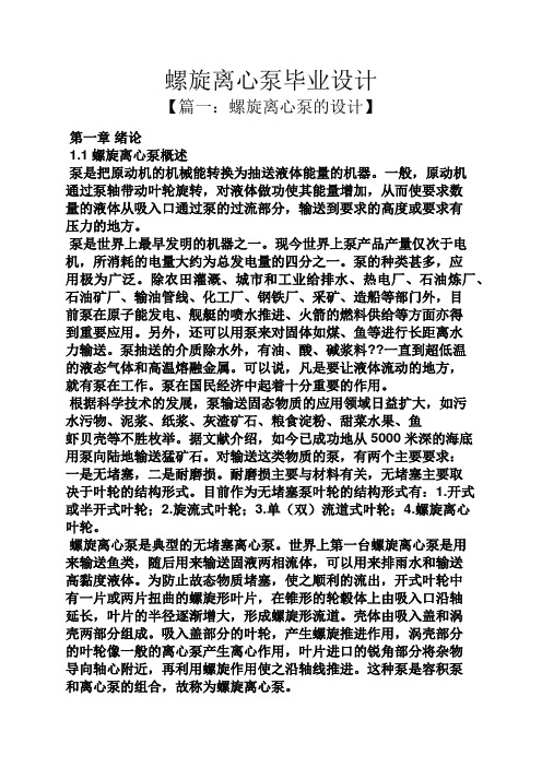
pressures up to 15 bar.Benefits•Low pulsation and very gentle pumping, making the pump ideal for sensitive products.•Minimized shearing for protecting end-product quality.•Low maintenance, increased process uptime.•Maximized performance and minimized risk ofcontamination.Standard designAll media contacting steel components, like the rotor case, front cover, rotors and rotor nuts, are in W. 1.4404 (AISI 316L). The robust stainless steel gearbox provides maximum shaft rigidity and easy oil seal replacement. The gearbox design is universal which enables the flexibility of mounting pumps with the inlet and outlet ports in either a vertical or horizontal plane by changing the foot and its position.The standard Alfa Laval SX has four-lobe rotors rated to 150°C, facilitating use with CIP and SIP processes.Fully front-loading and fully interchangeable single, single flushed, and double mechanical shaft seals are available. All media contacting elastomers are controlled compression joints, the latest technology where static and dynamic elastomer seals are used to prevent leakage of pumped media to the atmosphere.The Alfa Laval SX can be supplied either as a bare shaft pump or mounted on a base plate complete with coupling, guard, gear motor and shroud for easy, plug-and-play installation. Working principleA gear train in the pump gearbox drives the rotors and provides accurate synchronization of the multi-lobe rotors. The movement of the counter-rotating rotors creates a partial vacuum that allows atmospheric pressure or other external pressures to force fluid into the pump chamber. As the rotors revolve, an expanding cavity forms, filling with fluid. As the blades disengage, each dwell forms a cavity. As the rotor blades engage, the cavity diminishes, and fluid is displaced into the outlet port.TECHNICAL DATAInside surface finish:Mech Ra ≤ 0.8Gearbox:Stianless steel Base plate:Stainless steel Coupling guard:Stainless steel Rotor:Four-lobe Product wetted elastomers:EPDM Other elastomers:FPMShaft seal:Single mechanical (R00)Rotary seal face:CarbonStationary seal face:Stainless steelMax flush pressure, single flush:0.5 bar Max flush pressure, double mechanical: 1 bar over product pressure Water consumption, flushed or double mechanical:0.5 l/min Flush connections:BSPT or NPTMedia contacting elastomersAll media contacting elastomers are controlled compression joints, the latest technology where static and dynamic elastomerseals are used to prevent pumped media leaking to atmosphere.1.Front cover compression joint2.Spline sealing cup seal3.Cup seal4.Squad ringFlows/Pressures/ConnectionsSX1/0070.07 1.54 1.8540 1.571001200SX2/0130.128 2.82 3.3840 1.5152151000SX2/0180.181 3.98 4.7850271001000SX3/0270.266 5.857.03502152151000SX3/0350.357.709.25652.571001000SX4/0630.6313.8616.6565 2.5101451000SX5/0820.8218.0421.6765 2.515215600SX5/115 1.1525.3030.3880310145600SX6/140 1.4030.8036.9980315215500SX6/190 1.9041.8050.20100410145500SX7/250 2.5055.0066.05100415215500SX7/380 3.8083.60100.40150610145500Note 1. These pressure ratings may vary for pumps with certain threaded connections.SX210SX313SX416SX519SX625SX728WeightSX1/0071617SX2/0133233SX2/0183334SX3/0275759SX3/0355961SX4/046107110SX4/063113116SX5/082155155SX5/115165165SX6/140278278SX6/190290290SX7/250336344SX7/380358366Shaft Seal Options•Single or single flush/quench (steam barrier for aseptic application) R00 type mechanical seals.•Double R00 type mechanical seal for flush.All sealing options are fully front loading and fully interchangeable without the need for additional housings or pump component changes. Specialised seal setting of the mechanical seal is not required as the seal is dimensionally set on assembly. This feature further enhances fast and efficient on-site seal interchangeability.Materials for Mechanical SealsCarbon/Stainless Steel, Silicon Carbide/Silicon Carbide or variations of these materials to suit fluid being pumped and/or application requirements. The seal seat and face material combinations are all EHEDG compliant.Standard Specification Options•Screwed male inlet and outlet ports to DIN11851, DIN11864, SMS, ISS/IDF, RJT or Tri-clamp.•Heating/Cooling Jacket for Rotorcase Cover.•ATEX compliance.•Complete pump unit comprising: Pump + Baseplate (mild or stainless steel) + coupling with guard + Geared electric motor suitable for (or supplied with) frequency speed control or manual variable speed drive (advise motor enclosure and electrical supply).Pump SizingIn order to correctly size a rotary lobe pump some essential information is required. Provision of this information listed below enables our Technical Support personnel to obtain the optimum pump selection.Product/Fluid Data •Fluid to be pumped •Viscosity •SG/Density•Pumping temperature, minimum, normal and maximum•Cleaning in Place temperature(s), minimum, normal and maximum Performance Data•Flow rate, minimum, normal and maximum•Discharge head/pressure (closest to pump outlet)•Suction conditionBareshaft Pump DimensionsFigure 1. Vertically ported All dimensions in mmSX1/0074095113208151640305296601008022114104801017423.5SX2/0134010514725216225032632758.5111100121241241001221332.5SX2/0185010514725216225032634365.5111100121241241001221332.5SX3/0275012517530022286040843472.5142155151851551251424637.5SX3/0356512517530022286040845078142155151851551251424637.5SX4/04650150213363253880631051775174200172341841501430149.5SX4/06365150213363253880631053681.5174200172341841501430149.5SX5/082651752574322745110701460261264200202402201801435160SX5/115801752574322745110701463080.5264200202402201801435160SX6/140801902954852748110701469178267260203002502101440070SX6/1901001902954852748110701471990267260203002502101440070SX7/2501002053655702660110901876794288280253302902401847581.5SX7/38015020536557026601109018821121288280253302902401847581.5TOP SHAFTDRIVEFigure 2. Horizontally portedAll dimensions in mmSX1/007409590.5189101640671143052963612480101001008010SX2/0134010511523316225082.5147.532632738.51311001913212410012SX2/0185010511523316225082.5147.532634345.51311001913212410012SX3/027********.527218286010017540843469.51751253018115412514SX3/0356*******.5272182860100175408450751751253018115412514SX4/04650150163325203880113.5212.56310517752241503520218415014SX4/06365150163325203880113.5212.5631053681.52241503520218415014SX5/0826517519538222451101352557014602662791803524021018014SX5/115801751953822245110135255701463085.52791803524021018014SX6/1408019022543622481101552957014691782672602030022019014SX6/19010019022543622481101552957014719902672602030022019014SX7/250100205276.552427601101953589018767992732902534029024018SX7/380150205276.5524276011019535890188211262732902534029024018 This document and its contents are subject to copyrights and other intellectual property rights owned by Alfa Laval Corporate AB. No part of this document may be copied, re-produced ortransmitted in any form or by any means, or for any purpose, without Alfa Laval Corporate AB’s prior express written permission. Information and services provided in this document are made as a benefit and service to the user, and no representations or warranties are made about the accuracy or suitability of this information and these services for any purpose. All rights arereserved.200006104-2-EN-GB© Alfa Laval Corporate AB How to contact Alfa LavalUp-to-date Alfa Laval contact details for all countries are always availableon our website at 。
螺旋输送机的设计说明书

晋中学院本科毕业论文(设计)题目螺旋输送机变速系统的设计院系机械学院专业机械设计及其自动化姓名___ 曹伟佳_________________学号______1214312101_____________学习年限年月至年月指导教师田富根职称讲师申请学位学士学位年月日螺旋输送机变速系统的设计学生姓名:曹伟佳指导老师:田富根摘要:螺旋输送机是一种不具有挠性牵引构件的旋转类型的物料输送机械,是现代生产和物流运输不可缺少的重要机械设备之一。
它的广泛应用对于提高劳动生产率,实现物料输送过程的机械化和自动化,都具有重要的现实意义。
输送机可进行水平、倾斜和垂直输送,也可组成空间输送线路,输送线路一般是固定的,是现代化生产和物流运输不可或缺的重要机械设备。
它有输送能力强,运输距离长等优点。
本设计中详细介绍了机械式六挡三轴式螺旋输送机变速器的具体过程。
阐述了螺旋输送机变速器的功用、要求,介绍了变速器各种结构方案,说明了变速器主要参数的确定方法,齿轮的几何计算、强度计算等计算方法。
本设计主导思想即在于设计以提高汽车的动力性和经济性指标,具备较高的传动效率,操纵轻便,工作可靠,噪声小为目的的机械式变速器。
关键词:螺旋轴,变速系统,螺旋输送机。
The design of screw conveyorAuthor’s Name: Cao Weijia Tutor: Tian fugenABSTRACT: Screw conveyor is a component does not have traction flexible rotation type material conveying machinery, is one of the important equipment of modern production and logistics transportation indispensable. Its wide application will improve labor productivity, to achieve material conveying process of mechanization and automation, have important practical significance.Conveyor can undertake level, the tilt and vertical conveyor, also can make the space transport routes, transmission lines is usually fixed, is a modern production and logistics transport indispensable important mechanical equipment. It has transmission capacity is strong, long distance transportation etc.This paper introduces in detail the mechanical block six, three axis spiral conveyor transmission process. The transmission function of the screw conveyor ,requirements, the transmission of various structure scheme, illustrates theme tools to determine the main parameters of transmission, the gear geometry calculation, strength calculation, calculation method.This design idea is designed to improve the dynamic performance and fuel economy index, with high transmission efficiency, convenient operation, reliable work, low noise for mechanical transmission purposes.Keywords: sc rew axis, Transmission system. screw conveyor目录摘要 (1)ABSTRACT (2)1 前言 (1)1.1 课题背景 (1)1.2 设计的内容和要求 (2)1.3 螺旋输送机的简介 (2)1.4 螺旋输送机的设备组成 (4)1.5 螺旋输送机的发展概述 (4)1.6 螺旋输送机的研究现状 (5)2 螺旋输送机的总体设计 (6)2.1 电动机的选择 (6)2.2 工作部件的设计 (7)2.3主传动方案拟定 (7)3 变速系统的设计 (9)3.1 工作原理 (9)3.2 变速装置的设计.....................................3.3 轴的设计及其校核 (11)3.4轴承的设计及其校核3.5 齿轮的设计及其校核 (20)3.6 键的选择及其校核 (28)1前言1.1 课题背景随着现代工业的迅速发展和生产规模的扩大,生产成本中物料的输送费用所占的比例越来越大,因此选用合理地输送装置,选型设计的正确性是必要的。
Cascade 旋转泵手册说明书

ModelCatalog NumberParts Manualc For Technical Assistance call: 800-227-2233, Fax: 888-329-8207To Order Parts call: 888-227-2233, Fax: 888-329-0234Rotator 55G-RRB-24B R 5cascadecorporationSafety DecalsG RotatorREF QTY PART NO.DESCRIPTION 11679150No Step DecalPublicationsG Rotator6073002Installation Instructions672714Operator Guide6073955Service Manual679929Tool Catalog673964Literature Index Order FormRotator Group55GREF QTY PART NO.DESCRIPTION6052600Rotator Group (R6)116059682Baseplate216050782Faceplate31213761Bearing Assembly417401Grease Fitting596057357Capscrew, M12 x 45613213633Capscrew, M12 x 55717683822Lockwasher, M1281368073Drive Group u94763021Capscrew, M12 x 30 1024769572Capscrew, M12 x 35 1116080266Seal1216605Plug1316077615Cover Plate143767961Capscrew, M8 x 161517406Grease Fittingu See Drive Group page for parts breakdown. Reference: Common Parts 6059824-R6, Fastener Kit 6057411.REF QTY PART NO.DESCRIPTION368073Drive Group with 2.2 c.i. Motor 16769570Capscrew, M12 x 2521676855Cover31604510Fitting, 64l670574Shim – .010” (brown)5l671757Shim – .015” (pink)6l671758Shim – .020” (yellow)72670579Bearing81670582Key91670506Pinion101775551Housing111686465Gasket121675608Worm1322705O-Ring141670549Check Valve u1546444Lockwasher, 5/16 164607059Capscrew, 5/16 NC x 1.75 1716063316Check Valve u 1816097946Drive Motor – 2.2 c.i. n 191206406Drive Motor – 2.2 c.i. nl Quantity as required.u See Valve page for parts breakdown.REF QTY PART NO.DESCRIPTION 2013014870Seal2116033892Bearing H221675609Worm Gear231670581Bearing2417214Snap Ring251643423O-Ring261775552Cover271783609Seal281783608Capscrew, M10 x 16294200882Capscrew, M8 x 20301644010Relief Fitting3144468Capscrew, 3/8 NC x .75 321775553Adapter331670575Gasket344768798Capscrew, M8 x 40354787384Lockwasher, M8364221494Washer, M8371656300Gear Box Lube – 48 oz. 381668184Sealant670578Shim Service Kit (items 4-6,11,25,38) n See Drive Motor page for parts breakdown.H For service replacement use Bearing 670580.Check ValveREF QTY PART NO.DESCRIPTION670549Check Valve Assembly H 12609453Fitting, 1022670552Spring32670551Guide427020Ball52602580Fitting, 862673989Spring71670550Body H81670553SpoolH No longer available, replaced by 6063316 Valve Assembly.REF QTY PART NO.DESCRIPTION6063316Check Valve Assembly 116063282Valve Body226038929Check Valve – PO32667516Service KitDrive Motorn S ee Nameplate under valve for correct part number of Gerotor Set and Flange.l Compatible with water glycol based hydraulic fluids.Cascade provides service replacement parts for the listed parts only. Due to cost, if other parts need replacement, the complete drive motor should be replaced.l Compatible with water glycol based hydraulic fluids.Cascade provides service replacement parts for the listed parts only. Due to cost, if other parts need replacement, the complete drive motor should be replaced.Fitting GroupFork Bar Group55GREF QTY PART NO.DESCRIPTION6065868Fork Bar Group 116062893Upper Bar 216065862Lower Bar318769574Capscrew, M16 x 35418678992Lockwasher, M1652775443Capscrew, M16 x 25Fork Group55GREF QTY PART NO.DESCRIPTION6052636Fork Assembly 116052631Fork217000209Knob u 317000194Pin u417000210Coiled Spring Pin uuIncluded in Pin Kit 7000031.Bolt-On Mounting GroupClass III, 0°REF QTY PART NO.DESCRIPTION6051625Mounting Group 11670527Upper Hook – LH 21670528Upper Hook – RH 38684295Capscrew, M16 x 3548684586Lockwasher, M1652675969Lower Hook64768572Capscrew, M16 x 130********Washer, M1684781534Nut, M1694689997Capscrew, M16 x 60101682067Center Spacer112767810Capscrew, M12 x 251226051804Spacer131669344Stop Block KitP A R T S O R D E R I N G L O G P U R C H A S E S E R I A L R E FC A S C ADE C U S T O M E R D A T E O R D E R N U M B E RP A G E N O .Q T Y P A R T N O .P A R T N O .D E S C R I P T I O N P R I C EDo you have questions you need answered right now? Call your nearest Cascade Parts Department.Visit us online at AMERICASCascade CorporationParts Sales2501 Sheridan Ave. Springfield, OH 45505Tel: 888-CASCADE (227-2233) Fax: 888-329-0234Cascade Canada Inc.5570 Timberlea Blvd.Mississauga, OntarioCanada L4W-4M6Tel: 905-629-7777Fax: 905-629-7785Cascade do BrasilRua João Guerra, 134Macuco, Santos - SPBrasil 11015-130Tel: 55-13-2105-8800Fax: 55-13-2105-8899EUROPE-AFRICACascade Italia S.R.L. European Headquarters Via Dell’Artigianato 137050 Vago di Lavagno (VR) ItalyTel: 39-045-8989111Fax: 39-045-8989160Cascade (Africa) Pty. Ltd. PO Box 625, Isando 1600 60A Steel Road Sparton, Kempton Park South AfricaTel: 27-11-975-9240 Fax: 27-11-394-1147ASIA-PACIFICCascade Japan Ltd. 2-23, 2-Chome, Kukuchi Nishimachi Amagasaki, Hyogo Japan, 661-0978 Tel: 81-6-6420-9771 Fax: 81-6-6420-9777Cascade Korea121B 9L Namdong Ind.Complex, 691-8 Gojan-DongNamdong-KuInchon, KoreaTel: +82-32-821-2051Fax: +82-32-821-2055Cascade-XiamenNo. 668 Yangguang Rd.Xinyang Industrial ZoneHaicang, Xiamen CityFujian ProvinceP.R. China 361026Tel: 86-592-651-2500Fax: 86-592-651-2571Cascade India MaterialHandling Private LimitedNo 34, Global Trade Centre1/1 Rambaugh ColonyLal Bahadur Shastri Road,Navi Peth, Pune 411 030(Maharashtra) IndiaPhone: +91 020 2432 5490Fax: +91 020 2433 0881Cascade Australia Pty. Ltd. 1445 Ipswich Road Rocklea, QLD 4107 AustraliaTel: 1-800-227-223Fax: +61 7 3373-7333Cascade New Zealand15 Ra Ora DriveEast Tamaki, AucklandNew ZealandTel: +64-9-273-9136Fax: +64-9-273-9137Sunstream IndustriesPte. Ltd.18 Tuas South Street 5Singapore 637796Tel: +65-6795-7555Fax: +65-6863-1368cCascade Corporation 2011 2-2011。
阿尔法拉瓦尔SX旋转泵系列产品介绍说明书
design.This gives the flexibility of mounting pumps with the inlet andoutlet ports in either a vertical or horizontal plane,by changing the foot and its position.The SX range in series5&6has dedicated gearbox castings,which also allows the inlet and outlet ports to be in either the vertical or horizontal plane.The SX series7has a dedicated gearbox casting allowing inlet and outlet ports in a vertical plane only.Pump head ConstructionThe SX pump has sanitary design full bore inlet and outlet ports to International Standards,maximising inlet and outlet port efficiency and NPSH characteristics.Vertical porting and unique rotorcase internal profile enhances self-draining and self venting while maintaining optimum volumetric efficiency.The SX pump has four lobe rotors,designed using CFD(Computational Fluid Dynamics)to develop the optimum rotor geometry-possibly the first rotary lobe pump to be developed using this technology.All rotors are rated to302°F facilitating use with CIP/SIP processes.Maximum Solid Size CapabilityPump sizes Max.size of spherical solids(in.) SX10.28SX20.39SX30.51SX40.63SX50.75SX60.98SX7 1.10Materials of ConstructionPump gearbox-stainless steel304(series1-4)-cast iron painted grey(series5-7)Pumphead-product wetted components in316L.Product wetted elastomers of EPDM,MVQ,FPM all FDA conforming. All media contacting elastomers are controlled compression joints,the latest technology where static and dynamic elastomer seals are used to prevent pumped media leaking to atmosphere.All product wetted rubberparts are in compliance with FDA section21 CFR177.2600§ion21CFR177.1550(PTFE).EPDM Elastomers are furthermore in compliance with USP Class VI section88biological reactivity test,inVivo.1.Front cover compression joint2.Spline sealing cup seal3.Cup seal4.Squad ringWeightBare Shaft Pump(lbs.)Model Horizontalporting Vertical portingSX1NLD3739 SX1WLD3941 SX2NLD7577 SX2WLD7779 SX3NLD130134 SX3WLD134138 SX4NLD247254 SX4WLD260267 SX5NLD342342 SX5WLD364364 SX6NLD613613 SX6WLD639639 SX7NLD-750 SX7WLD-798Shaft Seal Options-Single or single flush/quench(steam barrier for aseptic application)R00type mechanical seals.-Double R00type mechanical seal for flush.All sealing options are fully front loading and fully interchangeable without the need for additional housings or pump component changes. Specialised seal setting of the mechanical seal is not required as the seal is dimensionally set on assembly.This feature further enhances fast and efficient on-site seal interchangeability.Materials for Mechanical SealsCarbon/Stainless Steel,Silicon Carbide/Silicon Carbide or variations of these materials to suit fluid being pumped and/or application requirements.The seal seat and face material combinations are all EHEDG compliant.Pump SizingIn order to correctly size a rotary lobe pump some essential information is required.Provision of this information listed below enables our Technical Support personnel to obtain the optimum pump selection. Product/Fluid Data-Fluid to be pumped-Viscosity-SG/Density-Pumping temperature,minimum,normal and maximum-Cleaning in Place temperature(s),minimum,normal and maximum Performance Data-Flow rate,minimum,normal and maximum-Discharge head/pressure(closest to pump outlet)-Suction conditionStandard Specification Options-Tri-clamp inlet and outlet ports standard-Screwed male inlet and outlet ports to DIN11851,SMS,ISS/IDF, RJT or Tri-clamp.-Heating/Cooling Jacket for Rotorcase Cover.-Electropolished product wetted components.-Full material traceability on request to EN10204.3.1.-ATEX compliance.-Complete pump unit comprising:Pump+Baseplate(mild or stainless steel)+coupling with guard+Geared electric motorsuitable for(or supplied with)frequency speed control or manual variable speed drive(advise motor enclosure and electrical supply).Working PrincipleThe positive displacement of the SX pump is provided by non-contacting,contra rotating four lobe rotors within a fully swept pump chamber.Flows/Pressures/ConnectionsDisplacement Inlet and OutletConnection SizeDifferential Pressure(see note1)MaximumSpeedSX Series SX ModelLitre/rev Imp gall/100rev US gall/100rev mm in bar psi rev/min SX1NLD0.05 1.11 1.32251121751200 1SX1WLD0.07 1.54 1.8540 1.571001200SX2NLD0.128 2.82 3.3840 1.5152151000 2SX2WLD0.181 3.98 4.7850271001000SX3NLD0.266 5.857.03502152151000 3SX3WLD0.357.709.2565 2.571001000SX4NLD0.4610.1212.15502152151000 4SX4WLD0.6313.8616.6565 2.5101451000SX5NLD0.8218.0421.6765 2.515215600 5SX5WLD 1.1525.3030.3880310145600SX6NLD 1.4030.8036.9980315215500 6SX6WLD 1.9041.8050.20100410145500SX7NLD 2.5055.0066.05100415215500 7SX7WLD 3.8083.60100.40150610145500 Note1.These pressure ratings may vary for pumps with certain threaded connections.Bareshaft Pump DimensionsVertically portedAll dimensions in inches,except where notedPUMP A B C D E F G J K L M N P Q R S T U V X SX1NLD 1.00 3.74 4.458.190.630.63 1.57 1.180.2010.87 2.13 3.94 3.150.87 4.49 4.09 3.150.397.050.93 SX1WLD 1.50 3.74 4.458.190.630.63 1.57 1.180.2011.38 2.36 3.94 3.150.87 4.49 4.09 3.150.397.050.93 SX2NLD 1.50 4.13 5.799.920.630.87 1.97 1.260.2412.76 2.32 4.37 3.940.47 4.88 4.88 3.940.478.62 1.28 SX2WLD 2.00 4.13 5.799.920.630.87 1.97 1.260.2413.39 2.60 4.37 3.940.47 4.88 4.88 3.940.478.62 1.28 SX3NLD 2.00 4.92 6.8911.810.87 1.10 2.36 1.570.3116.97 2.83 5.59 6.100.597.28 6.10 4.920.559.96 1.48 SX3WLD 2.50 4.92 6.8911.810.87 1.10 2.36 1.570.3117.60 3.03 5.59 6.100.597.28 6.10 4.920.559.96 1.48 SX4NLD 2.00 5.918.3914.290.98 1.50 3.15 2.480.3920.24 2.95 6.857.870.679.217.24 5.910.5512.09 1.95 SX4WLD 2.50 5.918.3914.290.98 1.50 3.15 2.480.3920.98 3.19 6.857.870.679.217.24 5.910.5512.09 1.95 SX5NLD 2.50 6.8910.1217.01 1.18 1.77 4.33 2.760.5523.58 2.4010.397.870.799.458.667.090.5513.58 2.36 SX5WLD 3.00 6.8610.1217.01 1.18 1.77 4.33 2.760.5524.65 3.1910.397.870.799.458.667.090.5513.58 2.36 SX6NLD 3.007.4811.6119.09 1.18 1.89 4.33 2.760.5527.05 3.0310.5110.240.7911.819.848.270.5515.75 2.76 SX6WLD 4.007.4811.6119.09 1.18 1.89 4.33 2.760.5528.15 3.5010.5110.240.7911.819.848.270.5515.75 2.76 SX7NLD 4.008.0714.3722.44 1.18 2.36 4.33 3.540.7130.04 3.7011.3411.020.9812.9911.429.450.7118.70 3.21 SX7WLD 6.008.0714.3722.44 1.18 2.36 4.33 3.540.7132.17 4.7611.3411.020.9812.9911.429.450.7118.70 3.21 Horizontally portedAll dimensions in inches,except where notedPUMP A B C D E F G HB HT J K L M N P Q R S T U SX1NLD 1.00 3.74 3.547.400.390.63 1.57 2.62 4.47 1.180.2010.87 1.46 4.61 3.150.98 4.53 3.94 3.150.39 SX1WLD 1.50 3.74 3.547.400.390.63 1.57 2.62 4.47 1.180.2011.38 1.69 4.61 3.150.98 4.53 3.94 3.150.39 SX2NLD 1.50 4.13 4.539.170.630.87 1.97 3.25 5.81 1.260.2412.76 1.54 5.16 3.940.75 5.20 4.88 3.940.47 SX2WLD 2.00 4.13 4.539.170.630.87 1.97 3.25 5.81 1.260.2413.39 1.81 5.16 3.940.75 5.20 4.88 3.940.47 SX3NLD 2.00 4.92 5.4310.750.71 1.1 2.36 3.96 6.91 1.570.3116.97 2.72 6.89 4.92 1.187.13 6.06 4.920.55 SX3WLD 2.50 4.92 5.4310.750.71 1.1 2.36 3.96 6.91 1.570.3117.60 2.91 6.89 4.92 1.187.13 6.06 4.920.55 SX4NLD 2.00 5.91 6.4212.800.79 1.5 3.15 4.478.37 2.480.3920.24 2.958.86 5.91 1.387.957.24 5.910.55 SX4WLD 2.50 5.91 6.4212.800.79 1.5 3.15 4.478.37 2.480.3920.98 3.198.86 5.91 1.387.957.24 5.910.55 SX5NLD 2.50 6.897.6814.800.79 1.77 4.33 5.3110.04 2.760.5523.58 1.8110.987.09 1.3810.838.277.090.55 SX5WLD 3.00 6.897.6814.800.79 1.77 4.33 5.3110.04 2.760.5524.65 2.6010.987.09 1.3810.838.277.090.55 SX6NLD 3.007.488.8616.890.79 1.89 4.33 6.1011.61 2.760.5527.05 3.0710.4710.2 1.5714.578.667.480.55 SX6WLD 4.007.488.8616.890.79 1.89 4.33 6.1011.61 2.760.5528.15 3.5410.4710.2 1.5714.578.667.480.55ESE00275ENUS1609Alfa Laval reserves the right to change specifications without priornotification.ALFA LAVAL is a trademark registered and owned by Alfa LavalCorporate AB.©Alfa LavalHow to contact Alfa LavalContact details for all countriesare continually updated on our website. Please visit toaccess the information direct.。
旋流泵简介

旋流泵简介● XLB型旋流泵应用范围和特点讫今为止,所有已知的泵的工作方式都有一个共同之处,就是泵体通过压力来输送物料介质,介质只有通过与输送机械元件(如齿轮、柱塞、隔膜、转子、叶片等)的接触才能被输送,机械部件对泵体和物料都产生严重冲击。
这种冲击对于输送高粘度介质、磨蚀性介质、含有固体颗粒介质、含有气体泡沫的介质或者液体、固体、气体混合的介质以及对剪切力比较敏感的介质而言是非常危险的,它会产生脉动,对泵有磨损,对管道有破坏。
我公司自主研发的XLB型旋流泵由于没有冲击性的部件来破坏所输送的物料介质,边界层可以保护泵,最大程度从根本上消除阻塞、气蚀、过度磨损、介质被破坏等所有影响泵性能的现象。
泵在这种条件很苛刻的场合更可靠、更有效率,也更经济,产品使用寿命大大延长。
●旋流泵适于输送各种流体介质1、磨蚀性的颗粒不会研磨和磨损旋转盘片表面,泵的性能和效率不会降低,所以泵的使用寿命会更长久。
2、由于无冲击性的破坏作用,介质不会受到剪切、搅拌、撞击等形式的破坏。
在旋盘泵腔内没有来自于叶轮的撞击或者其他有撞击性的部件,只有在非涡流性的流道里对流体的接触性输送,很多情况下对所输送产品的破坏完全能够消除。
3、当处理粘度大的流体介质时,还没有任何一种泵能够像旋流泵一样胜任。
实际上粘度越大,越能够增加效率,当粘度大于350cps时,旋流泵需要的功率比离心泵要低得多。
●旋流泵的工作原理旋流泵集中了离心泵结构简单和容积泵输送能力强的特点,靠介质内部的摩擦力和转盘旋转时产生的离心力来实现对介质的输送。
介质的流速直接取决于介质粘度和管壁粗糙度,管壁对流动的介质具有一种粘合力,这种粘合力会被传递到其他各层,直至管道的中心。
其结果是管道中间的介质流速为最大,管壁上的介质流速则为零。
旋流泵就是利用了这个原理,使两个或多个并排分布的圆盘产生旋转,在转盘壁上形成的边界层保持着一种固定的状态。
从转盘的表面上看,相对流速为零,而介质越往转盘中间的中心位置,其流速则越高。
- 1、下载文档前请自行甄别文档内容的完整性,平台不提供额外的编辑、内容补充、找答案等附加服务。
- 2、"仅部分预览"的文档,不可在线预览部分如存在完整性等问题,可反馈申请退款(可完整预览的文档不适用该条件!)。
- 3、如文档侵犯您的权益,请联系客服反馈,我们会尽快为您处理(人工客服工作时间:9:00-18:30)。
JIANGSU UNIVERSITY本科毕业设计毕业设计说明书学院名称:能源与动力工程学院专业班级:J动力流体0901学生姓名:杨锡平学号:3091104028指导老师:杨敏官高波李忠2013年6月毕业设计题目旋流泵设计(ns=63)目录第一章摘要----—————————————4 第二章叶轮水利设计———————————6 第一节概述—————————————6第二节参数计算———————————7 第三章压出室水利设计—————————— 26 第四章标准件的选用——————————— 31 第五章强度计算————————————— 32 附毕业小结——————————————39 参考文献——————————————40第一章摘要内容摘要泵可能是世界上除了发动机外运用最广泛的机械了,凡是有水流动的地方就会有泵在工作。
它被广泛应用于工业,农业,军事业等,已经成为人们生活所不可缺少的一部分。
矚慫润厲钐瘗睞枥庑赖。
旋流泵是离心泵的一种,因其内部流体存在旋转的漩涡运动而得名。
旋流泵多用于抽送复杂介质或含杂质流体,如含垃圾,短纤维物质或含便类的两相流体。
旋流泵亦称无堵塞泵,自由流泵或WEMCO泵。
聞創沟燴鐺險爱氇谴净。
本次设计的内容是旋流泵。
旋流泵设计的结构特点是叶片为开式或半开式叶片为直叶片并呈放射状布置。
叶轮与前泵壳之间有较宽的轴向空间,或者说叶轮后缩至泵壳后腔,这便为固体介质通过泵体提供了良好的条件。
残骛楼諍锩瀨濟溆塹籟。
AbstractPump may be the most universal machine in the world except for electric motor. where there is flowing water,there is a pump.It’s applied in many fields,such as industragriculture, military etc.Pump is essencial in people’s daily life.酽锕极額閉镇桧猪訣锥。
The vortex pump is a kind of centrifugal pump, named for its internal fluid rotation in vortex motion. The vortex pump used for pumping complex media the impurities fluid, such as with trash, short fibers material or faeces of two-phase fluid. V ortex pump, also known as non-clog pump, free-flow pump or WEMCO pump.The design of the contents of the vortex pump. The structural characteristics of the vortex pump impeller, said impeller for open or semi-open, straight blade and radial arrangement of leaves, wide axial space between the impeller and the pump casing or shrink to the pump housing cavity this solid mediathrough the pump a good condition.彈贸摄尔霁毙攬砖卤庑。
第二章水利设计第一节概述1.设计依据流量Q=45 (m3/h)扬程H=20 (m)转速n=1450 (r/min)效率η≥50%输送介质:常温清水结构形式:卧式2.设计内容叶轮的水力计算部分、叶轮水力图形的绘制等;然后是吸水室的设计、压出室的设计,以及水泵的整体结构图;最后是水泵标准件的选择与部分零件的强度计算。
謀荞抟箧飆鐸怼类蒋薔。
3.设计思路遵循泵的设计原理,泵的设计参数以及工作条件和性能要求等,并考虑了它的特点和应用上的介质特殊性,综合了各种因素的结果,具体步骤参照泵的设计手册和参考装配图纸而完成。
厦礴恳蹒骈時盡继價骚。
4设计意义更好的掌握泵的结构原理,对泵的结构有一个更加深入的了解。
第二节 参数计算一.确定泵的整体结构形式和进口直径1.结构形式:卧式2.进口直径:Ds考虑制造的经济性,取Vs=3m/s ,又Ds=VsQ π4代入数据得:Ds=0.0729m 取Ds=80mm3.出口直径Dd对于低压小流量泵,取出口直径Dd=Ds=80mm 4.比转速 ns=4365.3HQ n =4320360045145065.3⨯⨯=62.5655.估算泵的效率 h m v ηηηη=水力效率 h η=1+0.0835log 31450360045⨯=0.859圆盘损失效率m η=67)100(107.01s n ⨯-=67)10063(107.01⨯-=0.88 取轴承,填料损失为2%,则m η=0.863 容积效率v η=3268.011-+sn =326368.011-⨯+=0.959所以:711.0859.0863.0959.0=⨯⨯==h m v ηηηη6确定泵的轴功率Pd泵轴功率kw gQH P 446.3711.01000200125.08.91000/=⨯⨯⨯⨯==ηρ原动机为电动机,取k=1.25,传动为直联0.1=t η 配套功率:Pg=kw p kt30.4446.3125.1=⨯=⨯η 则选配套功率为4.5kw 电动机型号?满载转速1450r /min 同步转速1450r/min 茕桢广鳓鯡选块网羈泪。
其中:p 是有效功率二、 泵的轴径和叶轮轮毂直径的初步计算1、计算转子力矩Mm N n P M g .367.281450308.495509550=⨯=⨯= 2、轴的最小直径材料选用45号钢,调质处理HB=260~302,取[τ]=(58.9~88.3)MP 0133.010602.0367.282.0363min =⨯⨯==τM d m 取d=20mm 悬臂式单级泵h d =0mm 3、工艺要求:1)、在满足使用要求的前提下,轴的结构形式应尽量简化; 2)、为了便于装配零件,应去掉毛刺,轴端要倒角;3)、需磨削加工的轴段,应留有砂轮越程槽;4)、需切削螺纹的轴段,应留有退刀槽。
三、 叶轮主要尺寸的确定1.由s n 选取Z , b 2β , s n =63 , 旋流泵叶片通常选取6~12枚叶片,故取叶片数Z=6,出口安放角︒=302b β 见课本P125 ,表5~1选择b 2β应考虑的因素:⑴、 低比转速泵,选择大的b 2β角以增大扬程,减小2D ,从而减小圆盘摩擦损失,提高泵是效率;⑵、 增加b 2β角,在相同流量小叶轮出口速度2v 增加,压水室水力损失增加,并在小流量小冲角损失增加,易使特性曲线出现驼峰,因此b 2β不宜太大;鹅娅尽損鹌惨歷茏鴛賴。
⑶、 b 2β大,叶片间相对流动扩散严重;⑷、 为获得平坦的功率曲线,使泵在全扬程范围内运行, b 2β可小于10 度。
2、叶轮进口当量直径:m n Q K D 082.0~072.01450360045)0.4~5.3(3300=⨯⨯== mm D 800=3、叶轮出口直径:m nQ n n Q K D s 248.0~242.0)100)(6.9~35.9(321322===- 取m D 245.02=4. 叶轮进口直径:mm d D D h j 800802220=+=+= 5叶片出口宽度:m n k s b 476.0~435.0)100)(7.0~64.0(65==m n Q k k b b b 0122.0~011.01450360045)476.0~435.0(25.13322=⨯⨯== 取mm b 122=5. 精算叶轮外径第一次1)理论扬程m HH h t 3.23859.020===η 2)修正系数93.0)60301(62.0)601(2=+⨯=+=︒︒βαϕ 3)静距0067.0)04.01225.0(21)(2122212221=-=-==∆=⎰∑R R rdr R S s R R i i 4)有限叶片数修正系数260.00067.081225.093.0222=⨯⨯==ZS R p ϕ 5)无穷叶片数理论扬程36.293.23)260.01()1(=⨯+=+=∞t t H p H6)叶片出口排挤系数取2222)130cot (11︒+⨯-=D z πσφ取mm 42=σ 代入数据有:92.02=φ7)出口轴面速度s m D b Q V v m /94.1959.092.0245.00095.00125.02222=⨯⨯⨯⨯==πηϕπ 8)出口圆周速度代入数据得:∞++=t m m gH V V U 222222)tan 2(tan 2ββ 代入数据得 s m U /73.182=9)出口直径mm m n U D 249249.0145014.373.18606022==⨯⨯==π与245mm 不符合 取mm D 2492=7,精算叶轮外径第二次1)叶片出口排挤系数取mm D z 4)130cot (1122222=︒+⨯-=σπσφ取 代入数据有:917.02=φ2) 出口轴面速度s m D b Q V v m /91.1959.0917.0249.00095.014.30125.02222=⨯⨯⨯⨯==ηϕπ3) 出口圆周速度∞++=t m m gH V V U 222222)tan 2(tan 2ββ 代入数据得:s m U /7.182=4)叶轮出口直径 mm m n U D 4.2462464.0145014.37.18606022==⨯⨯==π与mm D 2492=相似 故取mm D 2492=5)叶轮出口速度1)出口轴面速度s m D b Q V v m /91.1959.0917.0249.00095.014.30125.02222=⨯⨯⨯⨯==ηϕπ 2)出口圆周速度∞++=t m m gH V V U 222222)tan 2(tan 2ββ 代入数据得:s m U /7.182=3)出口圆周速度s m u gH V t u /21.127.183.238.922=⨯==四.轴面投影图的绘制1、找相近比转数叶轮的轴面投影图作为参考,根据前面计算所得到的叶轮基本尺寸,初步作叶轮的轴面投影图。
检查轴面投影图过流断面面积变化,在流道内作内切圆,并将圆心连接起来,得到一条曲线,此为流道中线,求出每个圆的轴面液流过流断面及其面积F,而后作出沿轴面投影图中线的过流断面面积变化曲线,我们希望F~l曲线基本上为一条直线,即要求从叶轮进口到出口沿中线l面积F的变化是均匀的,如果该曲线不理想,则应修改轴面投影图,直到检查F~l 曲线满意为止。