Spec CV2820B2-0FBZ0规格书
MAX2820EVKIT中文资料
General DescriptionThe MAX2820/MAX2820A and MAX2821/MAX2821A single-chip zero-IF transceivers are designed for the 802.11b (11Mbps) applications operating in the 2.4G Hz to 2.5G Hz ISM band. The transceivers are nearly identical, except the MAX2821 and MAX2821A also provide a low-power shutdown mode and an ana-log voltage reference output. The MAX2820A/MAX2821A are cost-reduced versions, virtually identi-cal in pinout and performance to the MAX2820/MAX2821. The transceivers include all the circuitry required to implement an 802.11b RF-to-baseband transceiver solution, providing a fully integrated receive path, transmit path, VCO, frequency synthesis,and baseband/control interface. Only a PA, RF switch,RF BPF, and a small number of passive components are needed to form the complete radio front-end solution.The ICs eliminate the need for external IF and base-band filters by utilizing a direct-conversion radio archi-tecture and monolithic baseband filters for both receiver and transmitter. They are specifically opti-mized for 802.11b (11Mbps CCK) applications. The baseband filtering and Rx and Tx signal paths support the CCK modulation scheme for BER = 10-5 at the required sensitivity levels.The devices are suitable for the full range of 802.11b data rates (1Mbps, 2Mbps, 5.5Mbps, and 11Mbps) and also the higher-rate 22Mbps PBCC TM standard. The MAX2820 and MAX2821 are available in a 7mm ×7mm 48-lead QFN package. The MAX2820, MAX2821,MAX2820A, and MAX2821A are available in a 48-lead thin QFN package.Applications802.11b 11Mbps WLAN802.11b +22Mbps PBCC High-Data-Rate WLAN 802.11a + b Dual-Band WLAN 2.4GHz ISM Band RadiosFeatureso 2.4GHz to 2.5GHz ISM Band Operationo 802.11b (11Mbps CCK and 22Mbps PBCC) PHY Compatible o Complete RF-to-Baseband TransceiverDirect-Conversion Upconverters and DownconvertersMonolithic Low-Phase-Noise VCO Integrated Baseband Lowpass FiltersIntegrated PLL with 3-Wire Serial Interface Digital Bias Control for External PATransmit Power Control (Range > 25dB)Receive Baseband AGC (Range > 65dB)Complete Baseband Interface Digital Tx/Rx Mode ControlAnalog Receive Level Detection o -97dBm Rx Sensitivity at 1Mbps o -87dBm Rx Sensitivity at 11Mbps o +2dBm Transmit Power (11Mbps CCK)o Single +2.7V to +3.6V Supplyo Low-Current Shutdown Mode (MAX2821 only)o Very Small 48-Pin QFN Package(s)MAX2820/MAX2820A/MAX2821/MAX2821A2.4GHz 802.11b Zero-IF Transceivers________________________________________________________________Maxim Integrated Products 1Ordering Information19-2493; Rev 5; 5/05For pricing, delivery, and ordering information,please contact Maxim/Dallas Direct!at 1-888-629-4642, or visit Maxim’s website at .Pin Configuration/Functional Diagram and Typical Application Circuit appear at end of data sheet.PBCC is a trademark of Texas Instruments, Inc.M A X 2820/M A X 2820A /M A X 2821/M A X 2821A2.4GHz 802.11b Zero-IF TransceiversABSOLUTE MAXIMUM RATINGSDC ELECTRICAL CHARACTERISTICS(MAX2820/MAX2821 EV kit: V CC = +2.7V to +3.6V, RF_GAIN = V IH , 0V ≤V TX_GC ≤+2.0V, 0V ≤V RX_AGC ≤+2.0V, RBIAS = 12k Ω, no input signals at RF and baseband inputs, all RF inputs and outputs terminated into 50Ω, receiver baseband outputs are open, trans-mitter baseband inputs biased at +1.2V, registers set to default power-up settings, T A = -40°C to +85°C, unless otherwise noted.Typical values are at V CC = +2.7V, T A = +25°C, unless otherwise noted.) (Note 1)Stresses beyond those listed under “Absolute Maximum Ratings” may cause permanent damage to the device. These are stress ratings only, and functional operation of the device at these or any other conditions beyond those indicated in the operational sections of the specifications is not implied. Exposure to V CC Pins to GND...................................................-0.3V to +4.2V RF Inputs: RX_RFP, RX_RFN to GND.........-0.3V to (V CC + 0.3V)RF Outputs: TX_RFP, TX_RFN to GND..................-0.3V to +4.2V Baseband Inputs: TX_BBIP, TX_BBIN, TX_BBQP,TX_BBQN to GND ...................................-0.3V to (V CC + 0.3V)Baseband Outputs: RX_BBIP, RX_BBIN, RX_BBQP,RX_BBQN to GND...................................-0.3V to (V CC + 0.3V)Analog Inputs: RX_AGC, TX_GC, TUNE, ROSCN,ROSCP to GND.......................................-0.3V to (V CC + 0.3V)Analog Outputs: PA_BIAS, CP_OUT, VREFto GND.....................................................-0.3V to (V CC + 0.3V)Digital Inputs: RX_ON, TX_ON, SHDNB, CSB, SCLK,DIN, RF_GAIN, RX_1K to GND................-0.3V to (V CC + 0.3V)Bias Voltages: RBIAS, BYP..................................+0.9V to +1.5V Short-Circuit Duration Digital Outputs: DOUT, RX_DET.........10s RF Input Power: RX_RFN, RX_RFP.................................+10dBm Continuous Power Dissipation (T A = +70°C)48-Lead QFN (derate 27.0mW/°C above +70°C)...........2162mW 48-Lead Thin QFN (derate 38.5mW/°Cabove +70°C)...................................................................3077mW Operating Temperature Range ...........................-40°C to +85°C Junction Temperature......................................................+150°C Storage Temperature Range.............................-65°C to +160°C Lead Temperature (soldering, 10s).................................+300°CMAX2820/MAX2820A/MAX2821/MAX2821A2.4GHz 802.11b Zero-IF TransceiversDC ELECTRICAL CHARACTERISTICS (continued)(MAX2820/MAX2821 EV kit: V CC = +2.7V to +3.6V, RF_GAIN = V IH , 0V ≤V TX_GC ≤+2.0V, 0V ≤V RX_AGC ≤+2.0V, RBIAS = 12k Ω, no input signals at RF and baseband inputs, all RF inputs and outputs terminated into 50Ω, receiver baseband outputs are open, trans-mitter baseband inputs biased at +1.2V, registers set to default power-up settings, T A = -40°C to +85°C, unless otherwise noted.AC ELECTRICAL CHARACTERISTICS—RECEIVE MODE(MAX2820/MAX2821 EV kit: V CC = +2.7V to +3.6V, f RF and f LO = 2400MHz to 2499MHz, f OSC = 22MHz or 44MHz, receive baseband outputs = 500mV P-P , SHDNB = RX_ON = V IH , TX_ON = V IL , CSB = V IH , SCLK = DIN = V IL , RF_GAIN = V IH , 0V ≤V RX_AGC ≤+2.0V,RBIAS = 12k Ω, I CP = +2mA, BW PLL = 45kHz, differential RF input matched to 50Ω, registers set to default power-up settings, T A =+25°C, unless otherwise noted. Typical values are at V CC = +2.7V, f LO = 2437MHz, f OSC = 22MHz, unless otherwise noted.) (Note 1)M A X 2820/M A X 2820A /M A X 2821/M A X 2821A2.4GHz 802.11b Zero-IF Transceivers 4_______________________________________________________________________________________AC ELECTRICAL CHARACTERISTICS —RECEIVE MODE (continued)(MAX2820/MAX2821 EV kit: V CC = +2.7V to +3.6V, f RF and f LO = 2400MHz to 2499MHz, f OSC = 22MHz or 44MHz, receive baseband outputs = 500mV P-P , SHDNB = RX_ON = V IH , TX_ON = V IL , CSB = V IH , SCLK = DIN = V IL , RF_GAIN = V IH , 0V ≤V RX_AGC ≤+2.0V,RBIAS = 12k Ω, I CP = +2mA, BW PLL = 45kHz, differential RF input matched to 50Ω, registers set to default power-up settings, T A =AC ELECTRICAL CHARACTERISTICS—TRANSMIT MODEMAX2820/MAX2820A/MAX2821/MAX2821A2.4GHz 802.11b Zero-IF Transceivers (MAX2820/MAX2821EV kit: V CC= +2.7V to +3.6V, f RF and f LO= 2400MHz to 2499MHz, f OSC= 22MHz or 44MHz, transmit baseband inputs = 400mV P-P, SHDNB = TX_ON = V IH, RX_ON = V IL, CSB = V IH, 0V ≤V TX_GC≤+2.0V, RBIAS = 12kΩ, I CP= +2mA, BW PLL= 45kHz, differential RF output matched to 50Ωthrough a balun, baseband input biased at +1.2V, registers set to default power-up set-tings, T A= +25°C, unless otherwise noted. Typical values are at V CC= +2.7V, f LO= 2437MHz, f OSC= 22MHz, unless otherwise noted.)M A X 2820/M A X 2820A /M A X 2821/M A X 2821A2.4GHz 802.11b Zero-IF Transceivers 6_______________________________________________________________________________________AC ELECTRICAL CHARACTERISTICS —SYNTHESIZER(MAX2820/MAX2821 EV kit: V CC = +2.7V to +3.6V, f RF and f LO = 2400MHz to 2499MHz, f OSC = 22MHz or 44MHz, SHDNB = V IH ,CSB = V IH , RBIAS = 12k Ω, I CP = +2mA, BW PLL = 45kHz, registers set to default power-up settings, T A = +25°C, unless otherwise noted. Typical values are at V CC = +2.7V, f LO = 2437MHz, f OSC = 22MHz, unless otherwise noted.) (Note 11)AC ELECTRICAL CHARACTERISTICS —PA BIAS(MAX2820/MAX2821 EV kit: V CC = +2.7V to +3.6V, SHDNB = V IH , TX_ON = V IH , CSB = V IH , PA_BIAS enabled, RBIAS = 12k Ω, regis-ters set to default power-up settings, T = +25°C, unless otherwise noted. Typical values are at V = +2.7V, unless otherwise noted.)AC ELECTRICAL CHARACTERISTICS—SYSTEM TIMINGMAX2820/MAX2820A/MAX2821/MAX2821A2.4GHz 802.11b Zero-IF Transceivers (MAX2820/MAX2821 EV kit: V CC= +2.7V to +3.6V, f RF and f LO= 2400MHz to 2499MHz, f OSC= 22MHz or 44MHz, SHDNB = V IH, CSB = V IH, RBIAS = 12kΩ, I CP= +2mA, BW LOOP= 45kHz, registers set to default power-up settings, T A= +25°C, unless otherwisenoted. Typical values are at V CC= +2.7V, f LO= 2437MHz, f OSC= 22MHz, unless otherwise noted.) (Note 11)(MAX2820/MAX2821 EV kit: V CC= +2.7V to +3.6V, registers set to default power-up settings, T A= +25°C, unless otherwise noted.) (Note 11)Note 3:Noise-figure specification excludes the loss of the external balun. The external balun loss is typically ~0.5dB.Note 4:CCK interferer at 25MHz offset. Desired signal equals -73dBm. Interferer amplitude increases until baseband output from interferer is 10dB below desired signal. Adjacent channel rejection = P interferer- P desired.Note 5:Measured at balun input. Two CW tones at -43dBm with 15MHz and 25MHz spacing from the MAX2820/MAX2821 channel frequency. IP3 is computed from 5MHz IMD3 product measured at the RX I/Q output.Note 6:Two CW interferers at -38dBm with 24.5MHz and 25.5MHz spacing from the MAX2820/MAX2821 channel frequency. IP2 is computed from the 1MHz IMD2 product measured at the RX I/Q output.Note 7:Output power measured after the matching and balun. TX gain is set to maximum.Note 8:Adjacent and alternate channel power relative to the desired signal. TX gain is adjusted until the output power is -1dBm.Power measured with 100kHz video BW and 100kHz resolution BW.Note 9:Time required to reprogram the PLL, change the operating channel, and wait for the operating channel center frequency to settle within ±10kHz of the nominal (final) channel frequency.Note 10:Relative amplitude of reference spurious products appearing in the TX RF output spectrum relative to a CW tone at0.5MHz offset from the LO.Note 11:Min/max limits are guaranteed by design and characterization._______________________________________________________________________________________7M A X 2820/M A X 2820A /M A X 2821/M A X 2821A2.4GHz 802.11b Zero-IF Transceivers 8_______________________________________________________________________________________Typical Operating Characteristics(MAX2820/MAX2821 EV kit, V CC = +2.7V, f BB = 1MHz, f LO = 2450MHz, receive baseband outputs = 500mV P-P , transmit base-band inputs = 400mV P-P , I CP = +2mA, BW PLL = 45kHz, differential RF input/output matched to 50Ωthrough a balun, baseband input biased at +1.2V, registers set to default power-up settings, T A = +25°C, unless otherwise noted.)SUPPLY CURRENT vs. TEMPERATURETEMPERATURE (°C)I C C (m A )603510-151020304050607080901000-4085SUPPLY CURRENT vs. SUPPLY VOLTAGEV CC (V)I C C (m A )3.33.010203040506070809010002.73.6V RX_AGC (V)R X V O L T A G E G A I N (d B )1.51.00.5204060801001202.0RECEIVER VOLTAGE GAIN vs. GAIN-CONTROL VOLTAGERF FREQUENCY (MHz)R X V O L T A G E G A I N (d B )2480246024202440510152025303540024002500RECEIVER VOLTAGE GAIN vs. RF FREQUENCYRX GAIN (dB)N O I S E F I G U R E (d B )8060402051015202530354045500100RECEIVER NOISE FIGURE vs. GAINP IN (dBm)L O G I C L E V E L-40-45-50-55-60-65-35RECEIVER DETECTOR HYSTERESISvs. INPUT POWERFREQUENCY (kHz)N O R M A L I Z E D R E S P O N S E (d B )10010-80-70-60-50-40-30-20-10010-9011000RECEIVER FILTER RESPONSE(1kHz TO 1MHz)FREQUENCY (MHz)N O R M A L I Z E D R E S P O N S E (d B )10-80-70-60-50-40-30-20-10010-901100RECEIVER FILTER RESPONSE(1MHz TO 100MHz)RECEIVER LEAKAGE SPECTRUMFREQUENCY (GHz)R E C E I V E R L E A K A G E P O W E R (d B m )7.26.44.8 5.61.6 2.4 3.2 4.00.8-100-90-80-70-60-50-40-30-20-10-12008.0V RF_GAIN = V IH f LO = 2400MHzMAX2820/MAX2820A/MAX2821/MAX2821A2.4GHz 802.11b Zero-IF Transceivers_______________________________________________________________________________________9RECEIVER BASEBAND OUTPUT SPECTRUMFREQUENCY (MHz)B A S E B A N D O U T P U T P O W E R (d B m )45405101525302035-70-60-50-40-30-20-100-8050V RF_GAIN = V IH RX GAIN = 50dB f BB = 5MHz f LO = 2450MHzFREQUENCY (MHz)T X O U T P U T P O W E R (d B m )24802460242024400.51.01.52.02.53.03.54.0024002500TRANSMITTER OUTPUT POWERvs. FREQUENCYV CC (V)T X O U T P U T P O W E R (d B m )3.33.00.51.01.52.02.53.03.54.002.73.6TRANSMITTER OUTPUT POWERvs. SUPPLY VOLTAGE-90-80-70-60-50-40-30-20-10-33-11-22112233TRANSMITTER OUTPUT SPECTRUMFREQUENCY OFFSET FROM CARRIER (MHz)T X O U T P U T P O W E R (d B m )-80-60-70-40-50-30-200-101000.8 1.6 2.4 3.2 4.0 4.8 5.6 6.47.28.0TRANSMITTER OUTPUT SPECTRUMFREQUENCY (GHz)T X O U T P U T P O W E R (d B m )CW SIGNAL f BB = 3.3MHz f LO = 2450MHzV TX_GC (V)N O R M A L I Z E D G A I N (d B )1.51.00.5-30-25-20-15-10-505-352.0TRANSMITTER GAIN vs. GAIN-CONTROL VOLTAGETypical Operating Characteristics (continued)(MAX2820/MAX2821 EV kit, V CC = +2.7V, f BB = 1MHz, f LO = 2450MHz, receive baseband outputs = 500mV P-P , transmit base-band inputs = 400mV P-P , I CP = +2mA, BW PLL = 45kHz, differential RF input/output matched to 50Ωthrough a balun, baseband input biased at +1.2V, registers set to default power-up settings, T A = +25°C, unless otherwise noted.)M A X 2820/M A X 2820A /M A X 2821/M A X 2821A2.4GHz 802.11b Zero-IF Transceivers 10______________________________________________________________________________________-50-60-70-80-90-100-110-120-13010010k100k1k1MCLOSED-LOOP PHASE NOISE vs. OFFSET FREQUENCYOFFSET FREQUENCY (Hz)P H A S E N O I S E (d B c /H z )f LO = 2450MHz BW LOOP = 45kHz I CP = 2mA φINT = 2.1°RMSMAX2820/MAX2821("A" VERSION)MAX2820/MAX2821VCO/PLL SETTING TIMETIME (µs)F R E Q U E N C Y E R R O R (k H z )-40-30-20-1001020304050-5036032024028080120160200400400BW LOOP = 45kHzf LO = 2499MHz TO 2400MHzTypical Operating Characteristics (continued)(MAX2820/MAX2821 EV kit, V CC = +2.7V, f BB = 1MHz, f LO = 2450MHz, receive baseband outputs = 500mV P-P , transmit baseband inputs = 400mV P-P , I CP = +2mA, BW PLL = 45kHz, differential RF input/output matched to 50Ωthrough a balun, baseband input biased at +1.2V, registers set to default power-up settings, T A = +25°C, unless otherwise noted.)TRANSMITTER BASEBAND FILTER RESPONSEFREQUENCY (MHz)N O R M A L I Z E D R E S P O N S E (d B )908070605040302010-50-40-30-20-10010-60100f LO = 2450MHzLO FREQUENCY vs. TUNING VOLTAGEV TUNE (V)L O F R E Q U E N C Y (G H z )2.01.51.00.52.252.302.352.402.452.502.552.602.652.202.5-50-1401100010010OPEN-LOOP PHASE NOISE vs. OFFSET FREQUENCY-110-130-70-90-40-100-120-60-80OFFSET FREQUENCY (kHz)P H A S E N O I S E (d B c /H z )MAX2820/MAX2820A/MAX2821/MAX2821A Pin Configuration/Functional DiagramM A X 2820/M A X 2820A /M A X 2821/M A X 2821ASPI and QSPI are trademarks of Motorola, Inc. MICROWIRE is a trademark of National Semiconductor Corp.MAX2820/MAX2820A/MAX2821/MAX2821AM A X 2820/M A X 2820A /M A X 2821/M A X 2821APin Description (continued)Changes in “A” VersionThe MAX2820A/MAX2821A are cost-reduced versions of the original MAX2820/MAX2821, intended as a drop-in replacement —no changes to PC board layout, BOM,or control software are required. Functionally, the “A ”version removes unused functions and programmability while maintaining virtually identical performance char-acteristics. The changes are detailed below.SynthesizerThe original device has the ability to program the charge-pump source/sink current (±1mA or ±2mA); the “A ” version sets the charge-pump current at ±2mA, and bit SYNTH:D6 (ICP) should now always be pro-grammed to be 1.Receive FilterThe original device has the ability to control the base-band LPF corner; the “A ” version sets the LPF corner at 8.0MHz. Register bits RECEIVE:D2–D0 are now “don ’t cares.”Receive-Level Detector (RSSI)The original device has a receive-level detect output (pin 43, “RX_DET ”); the “A ” version removes this functionality.Pin 43 is a no-connect (N.C.) on the “A ” version.MAX2820/MAX2820A/MAX2821/MAX2821AOperating ModesThe MAX2820/MAX2821 have four primary modes of operation: shutdown, standby, receive active, and transmit active. The modes are controlled by the digital inputs SHDNB, TX_ON, and RX_ON. Table 1 shows the operating mode vs. the digital mode control input.Shutdown ModeShutdown mode is achieved by driving SHDNB low. In shutdown mode, all circuit blocks are powered down,except for the serial interface circuitry. While the device is in shutdown, the serial interface registers can still be loaded by applying V CC to the digital supply voltage (VCC_DIG). All previously programmed register values are preserved during the shutdown mode, as long as VCC_DIG is applied.Standby ModeStandby mode is achieved by driving SHDNB high and RX_ON and TX_ON low. In standby mode, the PLL,VCO, LO generator, LO buffer, LO quadrature, and fil-ter autotuner are powered on by default. The standby mode is intended to provide time for the slower-settling circuitry (PLL and autotuner) to turn on and settle to the correct frequency before making RX or TX active. The 3-wire serial interface is active and can load registervalues at any time. Refer to the serial-interface specifi-cation for details.Receive ModeReceive mode is enabled by driving the digital inputs SHDNB high, RX_ON high, and TX_ON low. In receive mode, all receive circuit blocks are powered on and all VCO, PLL, and autotuner circuits are powered on. None of the transmit path blocks are active in this mode. Although the receiver blocks turn on quickly, the DC offset nulling requires ~10µs to settle. The receiver signal path is ready ~10µs after a low-to-high transition on RX_ON.Transmit ModeTransmit mode is achieved by driving the digital inputs SHDNB high, RX_ON low, and TX_ON high. In transmit mode, all transmit circuit blocks are powered on and all VCO, PLL, and autotuner circuits are powered on.None of the receive path blocks is active in this mode.Although the transmitter blocks turn on quickly, the baseband DC offset calibration requires ~2.2µs to complete. In addition, the TX driver amplifier is ramped from the low-gain state (minimum RF output) to high-gain state (peak RF output) over the next 1µs to 2µs.The transmit signal path is ready ~4µs after a low-to-high transition on TX_ON.Figure 1. MAX2820/MAX2821 Serial-Interface Timing DiagramM A X 2820/M A X 2820A /M A X 2821/M A X 2821AProgrammable RegistersThe MAX2820/MAX2820A and MAX2821/MAX2821A (the MAX2820 family) contain programmable registers to control various modes of operation for the major cir-cuit blocks. The registers can be programmed through the 3-wire SPI/QSPI/MICROWIRE-compatible serial port. The MAX2820 family includes five programmable registers:1)Test register (always program as in Table 2).2)Block-enable register 3)Synthesizer register 4)Channel frequency register 5)Receiver settings register 6)Transmitter settings registerEach register consists of 16 bits. The four most signifi-cant bits (MSBs) are the register ’s address. The twelve least significant bits (LSBs) are used for register data.Table 2 summarizes the register configuration. A detailed description of each register is provided in Tables 3–6.Data is shifted in the MSB first. The data sent to the transceiver, in 16-bit words, is framed by CSB. When CSB is low, the clock is active and data is shifted with the rising edge of the clock. When CSB transitions to high, the shift register is latched into the register select-ed by the contents of the address bits. Only the last 16bits shifted into the device are retained in the shift reg-ister. No check is made on the number of clock pulses.Figure 1 documents the serial interface timing for the MAX2820 family.Power-Up Default StatesThe devices provide power-up loading of default states for each of the registers. The states are loaded on a VCC_DIG supply voltage transition from 0V to V CC . The default values are retained until reprogrammed through the serial interface or the power supply voltage is taken to 0V. The default state of each register is described in Table 3. Note:Putting the IC in shutdown mode does not change the contents of the programming registers.Block-Enable RegisterThe block-enable register permits individual control of the enable state for each major circuit block in the transceiver.The actual enable condition of the circuit block is a logical function of the block-enable bit setting and other control input states. Table 4 documents the logical definition of state for each major circuit block.Synthesizer RegisterThe synthesizer register (SYNTH) controls the reference frequency divider and charge-pump current of the PLL.See Table 5 for a description of the bit settings.Channel Frequency RegisterThe channel frequency register (CHANNEL) sets the RF carrier frequency for the radio. The channel is pro-grammed as a number from 0 to 99. The actual frequency is 2400 + channel in MHz. The default setting is 37 for 2437MHz. See Table 6 for a description of the bit settings.Receiver Settings Register (MAX2820/MAX2821 Only)The receive settings register (RECEIVE) controls the receive filter -3dB corner frequency, RX level detector midpoint, and VG A DC offset nulling parameters. The defaults are intended to provide proper operation.Table 2. Programming Register Definition Summary (Address and Data)MAX2820/MAX2820A/MAX2821/MAX2821ATable 4. Block-Enable Register (ENABLE)M A X 2820/M A X 2820A /M A X 2821/M A X 2821ATable 7a. Receive Settings Register (RECEIVE), (MAX2820/MAX2821 Only)Table 5. Synthesizer Register (SYNTH)Table 6. Channel Frequency Block Register (CHANNEL)fied if desired. Do not reprogram VGA DC offset nulling parameters. These settings were optimized during devel-opment. See Table 7 for a description of the bit settings.Transmitter Settings Register The transmitter settings register (TRANSMIT) controls the 4-bit PA bias DAC. The 4 bits correspond to a PA bias current between 0 and full scale (~300µA). See Table 8 for the bit settings.Applications InformationReceive PathLNA The RX_RF inputs are high-impedance RF differential inputs AC-coupled on-chip to the LNA. The LNA inputs require external impedance matching and differential to single-ended conversion. The balanced to single-ended conversion and interface to 50Ωis achieved through the use of an off-chip 2:1 balun transformer, such as the small surface-mount baluns offered by Murata and TOKO. In the case of the 2:1 balun, the RX RF input must be impedance-matched to a differen-tial/balanced impedance of 100Ω. A simple LC network is sufficient to impedance-match the LNA to the balun. The Typical Application Circuit shows the balun, induc-tors, and capacitors that constitute the matching net-work. Refer to the MAX2820/MAX2821 EV kit schematic for component values of the matching network.The line lengths and parasitics have a noticeable impact on the matching element values in the board-level circuit. Some empirical adjustment of LC component values is likely. Balanced line layout on the differential input traces is essential to maintaining good IP2 performance and RF common-mode noise rejection.controlled by the logic signal applied to RF_G AIN. RF_G AIN high enables the high-gain mode, and RF_GAIN low enables the low-gain mode. The LNA gain step is nominally 30dB. In most applications, RF_GAIN is connected directly to a CMOS output of the baseband IC, and the baseband IC controls the state of the LNA gain based on the detected signal amplitude.Receiver Baseband Lowpass Filtering The on-chip receive lowpass filters provide the steep filtering necessary to attenuate the out-of-band (>11MHz) interfering signals to sufficiently low levels to preserve receiver sensitivity. The filter frequency response is precisely controlled on-chip and does not require user adjustment. In the MAX2820/MAX2821, a provision is made to permit the -3dB corner frequency and entire response to be slightly shifted up or down in frequency. This is intended to offer some flexibility in trading off adjacent channel rejection vs. passband distortion. The filter -3dB frequency is programmed through the serial interface. The specific bit setting vs. -3dB frequency is shown in Table 7. The typical receive baseband filter gain vs. frequency profile is shown in the Typical Operating Characteristics.Receive Gain Control and DC Offset Nulling The receive path gain is varied through an external volt-age applied to the pin RX_AG C. Maximum gain is at V RX_AGC= 0V and minimum gain is at V RX_AGC= 2V. The RX_AG C input is a high-impedance analog input designed for direct connection to the RX_AG C DAC output of the baseband IC. The gain-control range, which is continuously variable, is typically 70dB. The gain-control characteristic is shown in the TypicalTable 8. Transmit Settings Register (TRANSMIT)MAX2820/MAX2820A/MAX2821/MAX2821AM A X 2820/M A X 2820A /M A X 2821/M A X 2821AOperating Characteristics section graph Receiver Voltage Gain vs. Gain-Control Voltage.Some local noise filtering through a simple RC network at the input is permissible. However, the time constant of this network should be kept sufficiently low in order not to limit the desired response time of the RX gain-control function.Receiver Baseband Amplifier OutputsThe receiver baseband outputs (RX_BBIP, RX_BBIN,RX_BBQP, and RX_BBQN) are differential low-imped-ance buffer outputs. The outputs are designed to be directly connected (DC-coupled) to the in-phase (I) and quadrature-phase (Q) ADC inputs of the baseband IC.The RX I/Q outputs are internally biased to +1.2V com-mon-mode voltage. The outputs are capable of driving loads up to 5k Ω|| 5pF with the full bandwidth baseband signals at a differential amplitude of 500mV P-P .Proper board layout is essential to maintain good bal-ance between I/Q traces. This provides good quadra-ture phase accuracy.Receiver Power Detector (MAX2820/MAX2821 Only)The receiver level detector is a digital output from an internal threshold detector that is used to determine when to change the LNA gain state. In most applications,it is connected directly to a comparator input of the base-band IC. The threshold level can be programmed through the MAX2820/MAX2821 control software.Transmit PathTransmitter Baseband InputsThe transmitter baseband inputs (TX_BBIP, TX_BBIN,TX_BBQP, and TX_BBQN) are high-impedance differ-ential analog inputs. The inputs are designed to be directly connected (DC-coupled) to the in-phase (I) and quadrature-phase (Q) DAC outputs of the baseband IC.The inputs must be externally biased to +1.2V common-mode voltage. Typically, the DAC outputs are current outputs with external resistor loads to ground. I and Q are nominally driven by a 400mV P-P differential base-band signal.Proper board layout is essential to maintain good bal-ance between I/Q traces. This provides good quadra-ture phase accuracy by maintaining equal parasitic capacitance on the lines. In addition, it is important not to expose the TX I/Q circuit board traces going from the digital baseband IC to the TX_BB inputs. The lines should be shielded on an inner layer to prevent cou-pling of RF to these TX I/Q inputs and possible enve-lope demodulation of the RF signal.Transmit Path Baseband Lowpass FilteringThe on-chip transmit lowpass filters provide the filtering necessary to attenuate the unwanted higher-frequency spurious signal content that arises from the DAC clock feedthrough and sampling images. In addition, the filter provides additional attenuation of the second sidelobe of signal spectrum. The filter frequency response is set on-chip. No user adjustment or programming is required. The Typical G ain vs. Frequency profile is shown in the Typical Operating Characteristics .Transmitter DC Offset CalibrationIn a zero-IF system, in order to achieve low LO leakage at the RF output, the DC offset of the TX baseband sig-nal path must be reduced to as near zero as possible.G iven that the amplifier stages, baseband filters, and TX DAC possesses some finite DC offset that is too large for the required LO leakage specification, it is necessary to “null ” the DC offset. The MAX2820 family accomplishes this through an on-chip calibration sequence. During this sequence, the net TX baseband signal path offsets are sampled and cancelled in the baseband amplifiers. This calibration occurs in the first ~2.2µs after TX_ON is taken high. During this time, it is essential that the TX DAC output is in the 0V differential state. The calibration corrects for any DAC offset.However, if the DAC is set to a value other than the 0V state, then an offset is erroneously sampled by the TX offset calibration. The TX DAC output must be put into the 0V differential state at or before the time TX_ON is taken high.Power-Amplifier Driver OutputThe TX_RF outputs are high-impedance RF differential outputs directly connected to the driver amplifier. The outputs are essentially open-collector outputs with an on-chip inductor choke connected to VCC_DRVR. The power-amplifier driver outputs require external imped-ance matching and differential to single-ended conver-sion. The balanced to single-ended conversion and interface to 50Ωis achieved through the use of an off-chip 4:1 balun transformer, such as one from Murata or TOKO. In this case, the TX RF output must be imped-ance-matched to a differential/balanced impedance of 200Ω. The Typical Application Circuit shows the balun,inductors, and capacitors that constitute the matching network of the power amplifier driver outputs. The out-put match should be adjusted until the return loss at the balun output is >10dB.。
HSMS-2820中文资料

∆VF - FORWARD VOLTAGE DIFFERENCE (mV) IF - FORWARD CURRENT (mA)
30
30
30
30
10
85°C
1
55°C
25°C
–5°C 0.1
–35°C
0.01 0.1 0.2 0.3 0.4 0.5 0.6 0.7 0.8 0.9
VF - FORWARD VOLTAGE (V)
HSMS-286X
7.0 0.18 0.69 10E-5 5.0 x 10E -8 1.08 5.0 0.65
2 0.5
4
IF - FORWARD CURRENT (mA)
∆VF - FORWARD VOLTAGE DIFFERENCE (mV)
IF - FORWARD CURRENT (mA)
Typical Parameters at TA = 25°C (unless otherwise noted), Single Diode
Note that HP’s manufacturing techniques assure that dice found in pairs and quads are taken from adjacent sites on the wafer, assuring the highest degree of match.
temperature.
Quad Capacitance
Capacitance of Schottky diode quads is measured using an HP4271 LCR meter. This instrument effectively isolates individual diode branches from the others, allowing accurate capacitance measurement of each branch or each diode. The conditions are: 20 mV R.M.S. voltage at 1 MHz. HP defines this measurement as “CM”, and it is equivalent to the capacitance of the diode by itself. The equivalent diagonal and adjacent capacitances can then be calculated by the formulas given below.
M34E02-FDW1TP;M34E02-FMB1TG;M34E02-FMC6TG;M34E02-FDW6TP;中文规格书,Datasheet资料
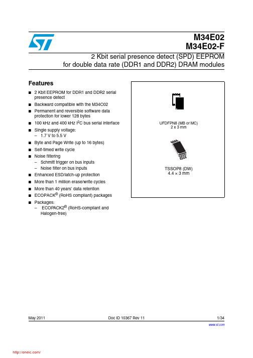
May 2011Doc ID 10367 Rev 111/34M34E02M34E02-F2 Kbit serial presence detect (SPD) EEPROMfor double data rate (DDR1 and DDR2) DRAM modulesFeatures■ 2 Kbit EEPROM for DDR1 and DDR2 serial presence detect■Backward compatible with the M34C02■Permanent and reversible software data protection for lower 128 bytes■100kHz and 400kHz I 2C bus serial interface ■Single supply voltage:– 1.7 V to 5.5 V■Byte and Page Write (up to 16 bytes)■Self-timed write cycle■Noise filtering–Schmitt trigger on bus inputs –Noise filter on bus inputs ■Enhanced ESD/latch-up protection ■More than 1 million erase/write cycles ■More than 40 years’ data retention ■ECOPACK ® (RoHS compliant) packages ■Packages:– ECOPACK2® (RoHS-compliant and Halogen-free)Contents M34E02, M34E02-FContents1Description . . . . . . . . . . . . . . . . . . . . . . . . . . . . . . . . . . . . . . . . . . . . . . . . . 62Signal description . . . . . . . . . . . . . . . . . . . . . . . . . . . . . . . . . . . . . . . . . . . 82.1Serial Clock (SCL) . . . . . . . . . . . . . . . . . . . . . . . . . . . . . . . . . . . . . . . . . . . 82.2Serial Data (SDA) . . . . . . . . . . . . . . . . . . . . . . . . . . . . . . . . . . . . . . . . . . . . 82.3Chip Enable (E0, E1, E2) . . . . . . . . . . . . . . . . . . . . . . . . . . . . . . . . . . . . . . 82.4Write Control (WC) . . . . . . . . . . . . . . . . . . . . . . . . . . . . . . . . . . . . . . . . . . . 82.5Supply voltage (V CC) . . . . . . . . . . . . . . . . . . . . . . . . . . . . . . . . . . . . . . . . . 92.5.1Operating supply voltage V CC . . . . . . . . . . . . . . . . . . . . . . . . . . . . . . . . . . . . . . . . . .92.5.2Power-up conditions . . . . . . . . . . . . . . . . . . . . . . . . . . . . . . . . . . . . . . . . 92.5.3Device reset . . . . . . . . . . . . . . . . . . . . . . . . . . . . . . . . . . . . . . . . . . . . . . . 92.5.4Power-down conditions . . . . . . . . . . . . . . . . . . . . . . . . . . . . . . . . . . . . . . 93Device operation . . . . . . . . . . . . . . . . . . . . . . . . . . . . . . . . . . . . . . . . . . . 113.1Start condition . . . . . . . . . . . . . . . . . . . . . . . . . . . . . . . . . . . . . . . . . . . . . 113.2Stop condition . . . . . . . . . . . . . . . . . . . . . . . . . . . . . . . . . . . . . . . . . . . . . 113.3Acknowledge bit (ACK) . . . . . . . . . . . . . . . . . . . . . . . . . . . . . . . . . . . . . . . 113.4Data input . . . . . . . . . . . . . . . . . . . . . . . . . . . . . . . . . . . . . . . . . . . . . . . . . 113.5Memory addressing . . . . . . . . . . . . . . . . . . . . . . . . . . . . . . . . . . . . . . . . . 123.6Setting the write-protection . . . . . . . . . . . . . . . . . . . . . . . . . . . . . . . . . . . 133.6.1SWP and CWP . . . . . . . . . . . . . . . . . . . . . . . . . . . . . . . . . . . . . . . . . . . 133.6.2PSWP . . . . . . . . . . . . . . . . . . . . . . . . . . . . . . . . . . . . . . . . . . . . . . . . . . 133.7Write operations . . . . . . . . . . . . . . . . . . . . . . . . . . . . . . . . . . . . . . . . . . . . 143.7.1Byte Write . . . . . . . . . . . . . . . . . . . . . . . . . . . . . . . . . . . . . . . . . . . . . . . 143.7.2Page Write . . . . . . . . . . . . . . . . . . . . . . . . . . . . . . . . . . . . . . . . . . . . . . . 143.7.3Minimizing system delays by polling on ACK . . . . . . . . . . . . . . . . . . . . . 163.8Read operations . . . . . . . . . . . . . . . . . . . . . . . . . . . . . . . . . . . . . . . . . . . . 163.8.1Random Address Read . . . . . . . . . . . . . . . . . . . . . . . . . . . . . . . . . . . . . 163.8.2Current Address Read . . . . . . . . . . . . . . . . . . . . . . . . . . . . . . . . . . . . . . 163.8.3Sequential Read . . . . . . . . . . . . . . . . . . . . . . . . . . . . . . . . . . . . . . . . . . 163.8.4Acknowledge in Read mode . . . . . . . . . . . . . . . . . . . . . . . . . . . . . . . . . 17 4Initial delivery state . . . . . . . . . . . . . . . . . . . . . . . . . . . . . . . . . . . . . . . . . 18 2/34Doc ID 10367 Rev 11M34E02, M34E02-F Contents5Use within a DDR1/DDR2 DRAM module . . . . . . . . . . . . . . . . . . . . . . . 185.1Programming the M34E02 and M34E02-F . . . . . . . . . . . . . . . . . . . . . . . . 185.1.1Isolated DRAM module . . . . . . . . . . . . . . . . . . . . . . . . . . . . . . . . . . . . . 185.1.2DRAM module inserted in the application motherboard . . . . . . . . . . . . 19 6Maximum rating . . . . . . . . . . . . . . . . . . . . . . . . . . . . . . . . . . . . . . . . . . . . 22 7DC and AC parameters . . . . . . . . . . . . . . . . . . . . . . . . . . . . . . . . . . . . . . 23 8Package mechanical data . . . . . . . . . . . . . . . . . . . . . . . . . . . . . . . . . . . . 28 9Part numbering . . . . . . . . . . . . . . . . . . . . . . . . . . . . . . . . . . . . . . . . . . . . 31 10Revision history . . . . . . . . . . . . . . . . . . . . . . . . . . . . . . . . . . . . . . . . . . . 32Doc ID 10367 Rev 113/34List of tables M34E02, M34E02-F List of tablesTable 1.Signal names . . . . . . . . . . . . . . . . . . . . . . . . . . . . . . . . . . . . . . . . . . . . . . . . . . . . . . . . . . . . 7 Table 2.Device select code . . . . . . . . . . . . . . . . . . . . . . . . . . . . . . . . . . . . . . . . . . . . . . . . . . . . . . . 10 Table 3.Operating modes . . . . . . . . . . . . . . . . . . . . . . . . . . . . . . . . . . . . . . . . . . . . . . . . . . . . . . . . 12 Table 4.DRAM DIMM connections . . . . . . . . . . . . . . . . . . . . . . . . . . . . . . . . . . . . . . . . . . . . . . . . . 18 Table 5.Acknowledge when writing data or defining the write-protection(instructions with R/W bit = 0). . . . . . . . . . . . . . . . . . . . . . . . . . . . . . . . . . . . . . . . . . . . . . . 19 Table 6.Acknowledge when reading the write protection (instructions with R/W bit = 1). . . . . . . . . 20 Table 7.Absolute maximum ratings. . . . . . . . . . . . . . . . . . . . . . . . . . . . . . . . . . . . . . . . . . . . . . . . . 22 Table 8.Operating conditions (for temperature range 1 devices) . . . . . . . . . . . . . . . . . . . . . . . . . . 23 Table 9.Operating conditions (for temperature range 6 devices) . . . . . . . . . . . . . . . . . . . . . . . . . . 23 Table 10.AC measurement conditions. . . . . . . . . . . . . . . . . . . . . . . . . . . . . . . . . . . . . . . . . . . . . . . . 23 Table 11.Input parameters. . . . . . . . . . . . . . . . . . . . . . . . . . . . . . . . . . . . . . . . . . . . . . . . . . . . . . . . . 24 Table 12.DC characteristics (for temperature range 1 devices) . . . . . . . . . . . . . . . . . . . . . . . . . . . . 24 Table 13.DC characteristics (for temperature range 6 devices) . . . . . . . . . . . . . . . . . . . . . . . . . . . . 25 Table 14.AC characteristics. . . . . . . . . . . . . . . . . . . . . . . . . . . . . . . . . . . . . . . . . . . . . . . . . . . . . . . . 26 Table 15.UFDFPN8 (MLP8) 8-lead ultra thin fine pitch dual flat package no lead2 x3 mm, data . . . . . . . . . . . . . . . . . . . . . . . . . . . . . . . . . . . . . . . . . . . . . . . . . . . . . . . . . . 29 Table 16.TSSOP8 – 8-lead thin shrink small outline, package mechanical data. . . . . . . . . . . . . . . . 30 Table 17.Ordering information scheme. . . . . . . . . . . . . . . . . . . . . . . . . . . . . . . . . . . . . . . . . . . . . . . 31 Table 18.Document revision history . . . . . . . . . . . . . . . . . . . . . . . . . . . . . . . . . . . . . . . . . . . . . . . . . 32 4/34Doc ID 10367 Rev 11M34E02, M34E02-F List of figures List of figuresFigure 1.Logic diagram. . . . . . . . . . . . . . . . . . . . . . . . . . . . . . . . . . . . . . . . . . . . . . . . . . . . . . . . . . . . 6 Figure 2.TSSOP and MLP connections (top view). . . . . . . . . . . . . . . . . . . . . . . . . . . . . . . . . . . . . . . 7 Figure 3.Device select code . . . . . . . . . . . . . . . . . . . . . . . . . . . . . . . . . . . . . . . . . . . . . . . . . . . . . . . . 8 Figure 4.Maximum R P value versus bus parasitic capacitance (C) for an I2C bus. . . . . . . . . . . . . . . 9 Figure 5.I2C bus protocol . . . . . . . . . . . . . . . . . . . . . . . . . . . . . . . . . . . . . . . . . . . . . . . . . . . . . . . . . 10 Figure 6.Result of setting the write protection. . . . . . . . . . . . . . . . . . . . . . . . . . . . . . . . . . . . . . . . . . 12 Figure 7.Setting the write protection (WC = 0) . . . . . . . . . . . . . . . . . . . . . . . . . . . . . . . . . . . . . . . . . 13 Figure 8.Write mode sequences in a non write-protected area . . . . . . . . . . . . . . . . . . . . . . . . . . . . 15 Figure 9.Write cycle polling flowchart using ACK. . . . . . . . . . . . . . . . . . . . . . . . . . . . . . . . . . . . . . . 15 Figure 10.Read mode sequences. . . . . . . . . . . . . . . . . . . . . . . . . . . . . . . . . . . . . . . . . . . . . . . . . . . . 17 Figure 11.Serial presence detect block diagram. . . . . . . . . . . . . . . . . . . . . . . . . . . . . . . . . . . . . . . . . 21 Figure 12.AC measurement I/O waveform. . . . . . . . . . . . . . . . . . . . . . . . . . . . . . . . . . . . . . . . . . . . . 23 Figure 13.AC waveforms . . . . . . . . . . . . . . . . . . . . . . . . . . . . . . . . . . . . . . . . . . . . . . . . . . . . . . . . . . 27 Figure 14.UFDFPN8 (MLP8) 8-lead ultra thin fine pitch dual flat package no lead2 x3 mm, outline . . . . . . . . . . . . . . . . . . . . . . . . . . . . . . . . . . . . . . . . . . . . . . . . . . . . . . . . 29 Figure 15.TSSOP8 – 8-lead thin shrink small outline, package outline . . . . . . . . . . . . . . . . . . . . . . . 30Doc ID 10367 Rev 115/34Description M34E02, M34E02-F 1 DescriptionThe M34E02 and M34E02-F are 2 Kbit serial EEPROM memories able to lock permanentlythe data in its first half (from location 00h to 7Fh). This facility has been designed specificallyfor use in DRAM DIMMs (dual interline memory modules) with serial presence detect (SPD).All the information concerning the DDR1 or DDR2 configuration of the DRAM module (suchas its access speed, size and organization) can be kept write-protected in the first half of thememory.The first half of the memory area can be write-protected using two different software writeprotection mechanisms. By sending the device a specific sequence, the first 128 bytes ofthe memory become write protected: permanently or resettable. In addition, the devicesallow the entire memory area to be write protected, using the WC input (for example bytieing this input to V CC).These I2C-compatible electrically erasable programmable memory (EEPROM) devices areorganized as 256 × 8 bits.I2C uses a two wire serial interface, comprising a bi-directional data line and a clock line.The devices carry a built-in 4-bit device type identifier code (1010) in accordance with theI2C bus definition to access the memory area and a second device type identifier code(0110) to define the protection. These codes are used together with the voltage level appliedon the three chip enable inputs (E2, E1, E0).The devices behave as a slave device in the I2C protocol, with all memory operationssynchronized by the serial clock. Read and Write operations are initiated by a Startcondition, generated by the bus master. The Start condition is followed by a device selectcode and RW bit (as described in the Device select code table), terminated by anacknowledge bit.When writing data to the memory, the memory inserts an acknowledge bit during the 9th bittime, following the bus master’s 8-bit transmission. When data is read by the bus master, thebus master acknowledges the receipt of the data byte in the same way. Data transfers areterminated by a Stop condition after an Ack for WRITE, and after a NoAck for READ.6/34Doc ID 10367 Rev 11M34E02, M34E02-F Description1.See the Package mechanical data section for package dimensions, and how to identify pin-1.Table 1.Signal namesSignal names DescriptionE0, E1, E2Chip EnableSDA Serial DataSCL Serial ClockWC Write ControlV CC Supply voltageV SS GroundDoc ID 10367 Rev 117/34Signal description M34E02, M34E02-F8/34Doc ID 10367 Rev 112 Signal description2.1Serial Clock (SCL)This input signal is used to strobe all data in and out of the device. In applications where thissignal is used by slave devices to synchronize the bus to a slower clock, the bus master must have an open drain output, and a pull-up resistor can be connected from Serial Clock (SCL) to V CC . (Figure 4 indicates how the value of the pull-up resistor can be calculated). In most applications, though, this method of synchronization is not employed, and so the pull-up resistor is not necessary, provided that the bus master has a push-pull (rather than open drain) output.2.2 Serial Data (SDA)This bidirectional signal is used to transfer data in or out of the device. It is an open drain output that may be wire-OR’ed with other open drain or open collector signals on the bus. A pull up resistor must be connected from Serial Data (SDA) to V CC . (Figure 4 indicates how the value of the pull-up resistor can be calculated).2.3 Chip Enable (E0, E1, E2)These input signals are used to set the value that is to be looked for on the three leastsignificant bits (b3, b2, b1) of the 7-bit device select code. In the end application, E0, E1 and E2 must be directly (not through a pull-up or pull-down resistor) connected to V CC or V SS to establish the device select code. When these inputs are not connected, an internal pull-down circuitry makes (E0,E1,E2) = (0,0,0).The E0 input is used to detect the V HV voltage, when decoding an SWP or CWP instruction.2.4 Write Control (WC)This input signal is provided for protecting the contents of the whole memory frominadvertent write operations. Write Control (WC) is used to enable (when driven low) or disable (when driven high) write instructions to the entire memory area or to the Protection Register.When Write Control (WC) is tied low or left unconnected, the write protection of the first half of the memory is determined by the status of the Protection Register.M34E02, M34E02-F Signal descriptionDoc ID 10367 Rev 119/342.5Supply voltage (V CC )2.5.1Operating supply voltage V CCPrior to selecting the memory and issuing instructions to it, a valid and stable V CC voltage within the specified [V CC (min), V CC (max)] range must be applied (see Table 8). In order to secure a stable DC supply voltage, it is recommended to decouple the V CC line with a suitable capacitor (usually of the order of 10nF to 100nF) close to the V CC /V SS package pins.This voltage must remain stable and valid until the end of the transmission of the instruction and, for a Write instruction, until the completion of the internal write cycle (t W ).2.5.2 Power-up conditionsThe V CC voltage has to rise continuously from 0V up to the minimum V CC operating voltagedefined in Table 8 and the rise time must not vary faster than 1V/µs.2.5.3 Device resetIn order to prevent inadvertent write operations during power-up, a power-on reset (POR)circuit is included. At power-up, the device does not respond to any instruction until V CC reaches the internal reset threshold voltage (this threshold is lower than the minimum V CC operating voltage defined in T able 8).When V CC passes over the POR threshold, the device is reset and enters the Standby Power mode. However, the device must not be accessed until V CC reaches a valid and stable V CC voltage within the specified [V CC (min), V CC (max)] range.In a similar way, during power-down (continuous decrease in V CC ), as soon as V CC drops below the power-on reset threshold voltage, the device stops responding to any instruction sent to it.2.5.4 Power-down conditionsDuring power-down (continuous decrease in V CC ), the device must be in Standby Powermode (mode reached after decoding a Stop condition, assuming that there is no internal write cycle in progress).2u l l -u k )Signal descriptionM34E02, M34E02-F10/34Doc ID 10367 Rev 112Table 2.Device select codeChip Enable signalsDevice type identifier Chip Enable bits RW b7(1)1.The most significant bit, b7, is sent first.b6b5b4b3b2b1b0Memory area select code (two arrays)(2)2.E0, E1 and E2 are compared against the respective external pins on the memory device.E2E1E011E2E1E0RW Set write protection (SWP)V SS V SS V HV (3)3.V HV is defined in Table 13.110010Clear write protection (CWP)V SS V CC V HV (3)0110Permanently set write protection (PSWP)(2)E2E1E0E2E1E00Read SWP V SS V SS V HV (3)0011Read CWP V SS V CC V HV (3)0111Read PSWP (2)E2E1E0E2E1E01分销商库存信息:STMM34E02-FDW1TP M34E02-FMB1TG M34E02-FMC6TG M34E02-FDW6TP。
SPECT╱CT技术规格

SPECT/CT技术参数与规格一、设备名称:单光子发射型计算机断层与螺旋CT复合诊断系统二、数量:1套三、规格:*全数字化、可变角双探头SPECT及16排CT系统四、技术要求和参数:1、探头性能1.1 全数字化探头1.2 矩形视野1.3 有效视野(NEMA UFOV): ≥530×380mm探头长轴大视野扫描*晶体厚度:3/8英寸*新型短型光电倍增管(PMT)≥59只/探头数/模转换:每个光电管有单独数字通道A/D转换固有能量范围:56-600KeV探头旋转采集角度≥540度*固有能量分辨率≤9.9%1.11 固有空间分辨率(UFOV)FWHM ≤3.9mm, (CFOV) FWHM≤3.8mm(UFOV)FWTM ≤7.7mm, (CFOV) FWTM≤7.5mm系统空间分辨率(低能高分辨型准直器@10cm FWHM)≤7.4mm固有均匀度(UFOV):微分≤2.3%,积分≤3.6%,(CFOV) :微分≤2.5%,积分≤3.0%固有空间线性(CFOV):微分≤0.2mm,积分≤UFOV) : 微分≤0.2mm,积分≤m单光子最大计数率≥310KCPS系统灵敏度:≥200 cpm/uci(低能通用准直器@10cm)两探头灵敏度差异≤5%PHA能窗个数≥16非能量依赖性:用同一种核素进行全能量均匀性校正提供全自动的实时能量、线性及均匀度自动校正系统提供全自动的实时旋转中心校正系统提供全自动的实时核素衰变校正系统,以减少人体内放射性核素衰变对图像质量的影响*探头具有全自动身体轮廓跟踪功能,双探头在180度状态进行平面和断层采集时具有此功能,以便获得高质量的图像。
为了确保高质量的心脏图像,探头在90度或76度状态时仍需具有全自动身体轮廓跟踪功能。
探头在行使全自动身体轮廓跟踪功能时,探头实时贴近人体体表的距离≤cm 探头全自动归位功能探头具有头尾角倾斜功能探头有心脏专用76度夹角2、机架及床配置2.1 SPECT为开放式机架、双探头、自由可变角度2.2 机架孔径≥70cm2.3 机架高度≤225cm2.4 机架重量≤4200kg2.5 双探头至少具有00,900,1800,反向1800这四种探头的采集角度,除了这四种角度以外,还可以做到对于特殊体位的病人没有采集角度的限制。
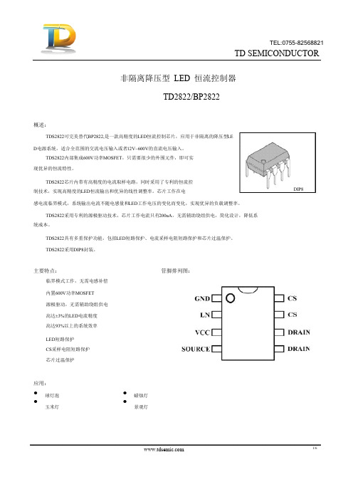
TD2822参数规格书
6/10
TD SEMICONDUCTOR
也会背离设计值。所以选择合适的电感值很重要。 保护功能:
TDS2822内置多种保护功能,包括输出LED短路保护,电流检测电阻短路保护和芯片过温保护。 芯片工作时自动检测负载状态,如果输出LED短路或电流检测电阻短路,芯片立刻进入短路保护状态, 功率MOSFET被关断。同时,芯片不断检测负载状态,直到故障解除,当外部短路故障解除后,芯片自动 恢复到正常工作。 内部过热保护电路检测芯片结温度,当结温度超过热保护阈值时,芯片进入过热保护状态,功率 MOSFET立刻被关断,直到结温度下降30℃以后,芯片才会退出过热保护状态,恢复到正常工作。 PCB设计: 在设计TDS2822 PCB时,需要遵循以下指南: 旁路电容:VCC的旁路电容需要紧靠芯片VCC和GND引脚。 地线:电流采样电阻的功率地线尽可能短,且要和芯片的地线及其它小信号的地线分头接到Bulk电容 的地端。 功率环路:功率环路的面积要尽量小,以减小EMI辐射。芯片远离续流二极管等发热元件。
现优异的恒流特性。
TDS2822芯片内带有高精度的电流取样电路,同时采用了专利的恒流控 制技术,实现高精度的LED恒流输出和优异的线性调整率。芯片工作在电 感电流临界模式,系统输出电流不随电感量和LED工作电压的变化而变化,实现优异的负载调整率。
TDS2822采用专利的源极驱动技术,芯片工作电流只有200uA,无需辅助绕组供电,简化设计,降低系 统成本。
从零开始上升,功率管的导通时间为: 其中,L是电感的感量;IPK 是流过电感的电流峰值;VIN是输入交流经整流后的直流电压;VLED是输
28202;中文规格书,Datasheet资料

599 Menlo Drive, Suite 100Rocklin, California 95765, USAOffice: (916) 624-8333Fax: (916) 624-8003General: info@Technical: support@Web Site: Educational: Gripper Kit for the Boe-Bot® Robot (#28202)The Gripper KitThis kit allows your Parallax Boe-Bot® Robot to pick up objects. TheBoe-Bot robot (#28132 serial or #28832 USB) is sold separately.Before getting started, take an inventory of the parts in your kit. UseFig #1 to identify each part to the parts list. Once you haveinventoried your kit, proceed to Step #1.11423456791011121315161783Recommended Tools•Small needle nosed pliers•Phillips #2 point screwdriver•Small flat-blade screwdriver• A sharp-tipped hobby knife,such as an X-Acto® knife-OR-A hand drill with 5/64″ bitWARNING!DO NOT use electricscrewdrivers with this kit. Pleaseassemble using hand tools onlyto avoid damaging your Gripper.Step #1: SpacersItem Qty Description 4 (2) Gripper link 5 (2) #4 x 1" spacer• Insert spacers into plastic Gripper links. • Use Fig #2 as a guide to install the spacers. Whendone, the pieces will appear as shown in Fig #3.Fig #2Fig #3Step #2: Gripper LinksItem Qty Description6 (1) Gripper plate7 (2) 4-40 x 1.25" pan head screw8 (2) 4-40 Hex Nut•Be sure the angled portions on top of the plastic links match the angles on top of the Gripper as shown in Fig #5.• Move links and spacers into the Gripper plate, thensecure with 4-40 screws and nuts as shown in Fig #4. • Tighten securely.• Before continuing, double check your work to ensurethat the pieces are angled as in Fig #5.Fig #4 Fig #5Step #3: Foam TapeItem Qty Description14 (4) foam tape• Cut four pieces of foam tape, each 2 inches long. •Apply foam tape to the Gripper plate as shown in Fig #7.This completes the left-side Gripper sub-assembly.Fig #6Fig #7Step #4: Second Gripper Sub-assemblyItem Qty Description4 (2) Gripper link5 (2) #4 x 1" spacer6 (1) Gripper plate7 (2) 4-40 x 1.25" pan head screw8 (2) 4-40 hex nut 14 (4) foam tape• Repeat Steps #1 through #3 to build the right-sideGripper sub-assembly in a similar fashion.• Be sure the angled portions of the links match with theGrippers face to face. Position the pieces exactly as they appear in Fig #8.• Double check your work, then proceed to Step #5.Fig #8•Assemble the Gripper sub-assemblies to the upperand lower linkage plates as shown in Fig #9. In turn, insert each plastic link, a spacer, and secure with 4-40 screws and nuts.• When all four plastic links are installed, tighten securely.•Double check your work against Fig #10. Note that the hinge tabs on the bottom plate face up, while hinge tabs on top plate face down.Step #5: Linkage PlatesItem Qty Description3 (2) linkage plate 5 (4)#4 x 1" spacer 7(4) 4-40 x 1.25" pan head screw 8 (4) 4-40 hex nutStep #6: Control ArmsItem Qty Description 10 (2) control arm 15 (4) 4-40 x ¼" pan head screw• Attach control arms with 4-40 x ¼" screws as shown in Fig #11.•Final assembly must match Fig #12. Double check your work, then proceed to Step #7.Fig #11Fig #12Step #7: E-Z ConnectorsItem Qty Description 13 (2) Brass 0.072 E-Z Connector• Follow the directions on the package to install the E/Z Connector into the control arms. Use the nylon washers, but set the screws aside for now.• Check your work; your final assembly should match Fig #13.Fig #13Step #8: Install Gripper Hinge PlateItem Qty Description1 (1) hinge mount 15 (3) 4-40 x ¼" pan head screw 8 (3) 4-40 hex nutNote: It is recommended that the servos and tires on the Boe-Bot be installed with the wheels biased toward the front of the unit as shown below. This will prevent the Boe-Bot from tipping when it picks up objects.• Attach hinge mount to the Boe-Bot with the 4-40 x ¼" screws and nuts as shown in Fig #14 and Fig #15. • Double check your work against Fig #16.Fig #14 Top ViewFig #15 Bottom ViewFig #16Assembled ViewStep #9: Position Gripper on Boe-BotItem Qty Description(1) Gripper assembly (1) Boe-Bot robot• Remove one wheel to allow for dowel pin installation in the next step, Step #10.• Position the Gripper assembly onto the hinge mount as shown in Fig #17 below.•Place the top hinge tabs over the tabs on the hinge mount so the top of the Gripper stays on the hinge mount.Fig #17Step #10: Insert Dowel Pin Item Qty Description2 (1) dowelpin• Insert dowel pin.•If dowel pin slips in very easily, use needle nose pliers to slightly crimp the center of the hinge plate.• Replace wheel.Fig #18Fig #19Fig #21Step #12: Servo BracketsItem Qty Description16 (2) servo brackets 17 (4) 4-40 x 3/8" pan head screw 8 (4) 4-40 hex nut 11 (1) Parallax Standard Serv o• Attach servo brackets to servo with 4-40 screws and nuts. Make sure the metal brackets are placed below the plastic servo tabs as shown in Fig #22.•The final assembly should match Fig #23. Double check your work, then proceed to Step #13.Note: Only one arm of the servo horn is shown for clarity.Fig #22Fig #23Step #13: Bend Actuator RodItem Qty Description 12 (1) actuator rod•Using the needle nose pliers, bend actuator rod at mid-point. Then bend as shown in Fig #24.Fig #24Step #14: Install Actuator Rod Item Qty Description12 (1) actuatorrod11 (1) Parallax Standard Servo•Thread bent rod through servo horn as shown in Fig #25.Fig #25分销商库存信息: PARALLAX 28202。
卫星接收器28207RF说明书
CH+/-CONNECTION FUNCTIONDISH IN Connect to satellite antenna cableLOOP OUT RF loop through output to another receiverRS-232Connects to PC for software updatesCOAXIAL Phono socket digital stereo output to TV or HiFi audio VCR SCART Connect to recording device (VCR/DVD) using SCART cable TV SCART Connect to TV using SCART cableAERIAL IN Signal input from local CATV network or outdoor TV antenna TO TV UHF RF output to TV set’s antenna inPOWER ON/OFF Power on/off the receiver2.1 Connection to Dish and TV via SCART Connect the SCART lead supplied to theand to either of the SCARTsockets on the back of the TV marked2.2 VCR SCART Connection3. Menu InformationAfter completing all your connections switch on the receiver,the main menu will be displayed, which consists of the4 menu items listed below.Channel ManagerPreferencesDuring installation the OK Keys confirms a selection and theKeys shows the menu options. You can also use thenumeric Keys on the RCU to select a channel while watching TV.Keys to move up or down from one line to another line. Use the/Keys to move the cursor up or down in the sub-menu. To quit the menu system at anytime, press the EXIT Key on the RCU.search multiple satellites in one operation. If you have a fixed dishIf quality is sufficient press the Blue Key. A sub-menu will appear giving two options.. NIT stands for Network Information Table and is a table of service information included in the data stream from the transponder if you wish to search this informationset the NIT search to On, usually we would advise you to leave this set to NIT Off .Option 2 allows you to choose the type of channels to search for:: Only searches the Free to air (Unencrypted) TV and Radio Channels: Only searches the Conditional Access Channels/Encrypted Channels (not available on this receiver).A window will open to show when the search is complete, press EXIT to quit the menu.5. Polarization: Enter the correct polarization for transponder HOR for Horizontal Polarization,VER for Vertical polarization, if you select the wrong polarization the Signal Quality will show Zero.: Only searches for the Free to air (Unencrypted) TV and Radio ChannelsOnly searches for the Conditional Access Channels/Encrypted Channels (not available on this receiver).: Includes both of the above. We advise you to set the Search Type to FREE .. NIT stands for Network Information Table and is a table of service information included in the data stream from the transponder if you wish to search this information set the NIT searchWhen you have made all your settings press the Blue Function Key to start the channel search.Red Function Key: To switch to the LNB Settings. Green Function Key: To Delete an Unwanted or Inactive TP (Transponder) from the default TP list. Yellow Function Key: Allows the user to input the Audio, Video and PCR PID’s with the numeric Keys on the RCU these can again be found in the channel information atStart Frequency: set to 10700 for a Universal LNB. End Frequency: set to 12750 for a Universal LNB.Start Symbol: Set to the Lowest Symbol rate you wish to search normally 1000End Symbol: Set to the Highest Symbol rate you wish to search normally 45000Polarization: Set to All to search both Horizontal and Vertical Transponders this is the default setting, Select HOR to search for Horizontal Polarization Transponders only or VER to search for Vertical PolarizationKeys to select the transponder you want to set, you can also press the OK Key to activate a transponder list, the parameters (settings) of the transponder can be found on or , some dish motor manuals come with a preferred transponder setting for each satelliteKey to turn the dish further East.This function automatically calculates and sets all the pre-programmed satellites positions with reference toYou can move channels to a better or more logical place in the channel list. Select the channel(s)Keys and then the OK Key if you wish to move a block of channels thenRed Function Key to confirm the selection, Keys to move your selection to the required place in the channel list and then press the OK KeyChoose the channel you want to rename some channels are listed as TV Ch in the channel list these can be renamed to make identification easier. Press the OK Key, a Keyboard will be displayed on the Keys to edit the channel name when you have finished move the cursor to the OKYou can sort the channels by Alphabet, Satellite, FTA/CAS Channels or Favorite channels.Press TV/Radio Key to change between TV and Radio channels. Radio channel management is the sameKeys on the front panel of the receiver or the /Keys or the numeric keys on the remote control unit (RCU). Also while listening to a Radio Channel or Watching a TV channel press the OK key this will display a channel list on the right hand side of the screen to select a on the RCU when you have selected the desired channel press the OK key to watch or listen. Pressing the EXIT key removes the channel list from the screen.on the RCU to move to the channel you watched previously.Press the TV/Radio key on the RCU to toggle between TV and Radio channel modeswill show any sub-title information available for the satellite channel selected.If a satellite channel is transmitting Teletext information this can be viewed by pressing the TXT (Red) Key , some providers use a specific coded signal on there transmissions these will not be able to be viewed on thisTetris Box ManCanvas Gobang9.EPG(ElectronicProgramGuide)The receiver provides an EPG function this provides the information from the channel or network like program titles, times, Satellite, Transponder etc, some European satellite networks provide a 7/10/14 day guide, while others only provide Now and Next program informationRed Function Key Shows yesterdays guideGreen Function Key Shows tomorrows guideShows a more detailed guide to the program informationPress the OK to activate the Timer function; use the / / Keys to change the Timer number as required and Timer Status to either Once, Daily, Weekly or Off, then select either OK or cancel and then press the OK。
半导体传感器TMS320F2808PZA中文规格书
TMS320F2810, TMS320F2810-Q1, TMS320F2811, TMS320F2811-Q1TMS320F2812, TMS320F2812-Q1SPRS174V – APRIL 2001 – REVISED FEBRUARY 2021Copyright © 2021 Texas Instruments Incorporated Submit Document Feedback17 Product Folder Links: TMS320F2810TMS320F2810-Q1TMS320F2811TMS320F2811-Q1TMS320F2812TMS320F2812-Q1TMS320F2810, TMS320F2810-Q1, TMS320F2811, TMS320F2811-Q1TMS320F2812, TMS320F2812-Q1SPRS174V – APRIL 2001 – REVISED FEBRUARY 20218.9 Thermal Resistance Characteristics for 176-Pin PGF Package(1)These values are based on a JEDEC defined 2S2P system (with the exception of the Theta JC [RΘJC] value, which is based on aJEDEC defined 1S0P system) and will change based on environment as well as application. For more information, see these EIA/JEDEC standards:•JESD51-2, Integrated Circuits Thermal Test Method Environmental Conditions - Natural Convection (Still Air)•JESD51-3, Low Effective Thermal Conductivity Test Board for Leaded Surface Mount Packages•JESD51-7, High Effective Thermal Conductivity Test Board for Leaded Surface Mount Packages•JESD51-9, Test Boards for Area Array Surface Mount Package Thermal Measurements8.10 Thermal Resistance Characteristics for 128-Pin PBK Package(1)These values are based on a JEDEC defined 2S2P system (with the exception of the Theta JC [RΘJC] value, which is based on aJEDEC defined 1S0P system) and will change based on environment as well as application. For more information, see these EIA/JEDEC standards:•JESD51-2, Integrated Circuits Thermal Test Method Environmental Conditions - Natural Convection (Still Air)•JESD51-3, Low Effective Thermal Conductivity Test Board for Leaded Surface Mount Packages•JESD51-7, High Effective Thermal Conductivity Test Board for Leaded Surface Mount Packages•JESD51-9, Test Boards for Area Array Surface Mount Package Thermal Measurements8.11 Thermal Design ConsiderationsBased on the end application design and operational profile, the I DD and I DDIO currents could vary. Systems that exceed the recommended maximum power dissipation in the end product may require additional thermal enhancements. Ambient temperature (T A) varies with the end application and product design. The critical factor that affects reliability and functionality is T J, the junction temperature, not the ambient temperature. Hence, care should be taken to keep T J within the specified limits. T case should be measured to estimate the operating junction temperature T J. T case is normally measured at the center of the package top-side surface. The thermal application report Semiconductor and IC Package Thermal Metrics helps to understand the thermal metrics and definitions.26Submit Document Feedback Copyright © 2021 Texas Instruments Incorporated Product Folder Links: TMS320F2810TMS320F2810-Q1TMS320F2811TMS320F2811-Q1TMS320F2812TMS320F2812-Q1。
科达产品手册
20 NVR2820A网络录像机 21 NVR2820E网络录像机 22 NVR2860网络录像机 23 NVR2880网络录像机
网络摄像机
高清网络摄像机
28 IPC110 高清枪型网络摄像机 29 IPC112高清低照度枪型网络摄像机 30 IPC120高清低照度枪型网络摄像机 31 IPC210高清红外防水网络摄像机 32 IPC211高清红外半球网络摄像机 33 IPC221高清红外半球网络摄像机 34 IPC212A高清防暴半球网络摄像机 35 IPC223高清防暴半球网络摄像机 36 IPC310高清室内型PTZ网络摄像机 37 IPC410高清高速球型网络摄像机 38 IPC412高清高速球型网络摄像机 39 IPC420高清高速球型网络摄像机 40 IPC510高清高速云台网络摄像机 41 IPC512高清激光云台网络摄像机
无线设备
69 KDM2424MB车载四路无线视频编码器 70 KDM2421MP单兵无线视频编码器 71 KDM2421MA存储型单路无线视频编码器(固定) 72 KDM2421MB存储型单路无线视频编码器(车载)
媒体接入网关
76 VS-G100E DVR接入网关 77 VS-G200 矩阵接入网关 78 VS-G300 数字系统接入网关 79 VS-G400E 会议监控互通网关 80 VS-G700E 手机监控接入网关 81 VS-G800E 媒体处理网关
1×RCA, Line In 1×RCA,Line Out
2×eSATA 8×SATA
2×eSATA 8×SATA
2×eSATA 8×SATA
2×eSATA 8×SATA
4×USB 2.0 4×USB 2.0 4×USB 2.0 4×USB 2.0
海康威视DS-2CD2820F说明书
DS-2CD2820F● 最高分辨率可达1920×1080 @ 30 fps,在该分辨率下可输出实时图像 ● 采用ROI 、SVC 等视频压缩技术,压缩比高,且处理非常灵活,超低码率 ● 码流平滑设置,适应不同场景下对图像质量、流畅性的不同要求 ● 支持GBK 字库,支持更多汉字及生僻字叠加 ● 支持OSD 颜色自选● 支持Micro SD/SDHC/SDXC 卡(64G)本地存储 ● ICR 红外滤片式自动切换,实现真正的日夜监控 ● 支持日夜两套参数独立配置 ● 支持PoE 供电功能● 支持3D 数字降噪,支持数字宽动态 ● 支持双码流,支持手机监控● 支持走廊模式,背光补偿,自动电子快门功能,适应不同监控环境 ● 功能齐全:心跳,镜像,一键恢复等● 支持智能报警:越界侦测,区域入侵侦测● 支持智能后检索,配合NVR 支持事件的二次检索分析● 支持GB28181接入,支持EHOME 平台接入,支持EZVIZ 平台接入 ● 支持NAS 、Email 、FTP 、NTP 服务器测试 ● 支持HTTPS,SSH 等安全认证,支持创建证书 ● web 支持basic 和digest 认证● 支持用户登录锁定机制,及密码复杂度提示适用于道路、仓库、地下停车场、酒吧、管道、园区等光线较暗或无光照环境且要求高清画质的场所DS-2CD2820FDS-1213ZJ 护罩壁装支架适用于室外DS-1212ZJ 壁装支架 适用于室内DS-1322HZ-C/H/CW/HW 室外护罩DS-1320HZ 室内护罩TV0309D-MPIR自动光圈手动变焦三百万像素红外镜头TV0550D-MPIR自动光圈手动变焦三百万像素红外镜头功能特性应用场景订货型号推荐配件外形尺寸技术参数型号DS-2CD2820F*须另备DC12V电源。
- 1、下载文档前请自行甄别文档内容的完整性,平台不提供额外的编辑、内容补充、找答案等附加服务。
- 2、"仅部分预览"的文档,不可在线预览部分如存在完整性等问题,可反馈申请退款(可完整预览的文档不适用该条件!)。
- 3、如文档侵犯您的权益,请联系客服反馈,我们会尽快为您处理(人工客服工作时间:9:00-18:30)。
CAMERA MODULE PRODUCTSPECIFICATION FOR APPROVAL 產品規格承認書Model No. : CV2820B3-0FBZCustomer客戶名稱Date Submitted送樣日期Description 產品內容2.0M 攝像頭模組122.16×22×21.6mm/FPC-24PinApprove確認回簽CAMERA MODULE PRODUCTSpecification for CV2820B3-0FBZTable of Contents1. Scope (2)2. General Description ................................................................................................... . (2)3. Features (2)4. Applications (2)5. Component Specifications (3)6. Electrical Specifications (4)7. Module Drawing (6)8. Reliability Test (7)1. ScopeThis document contains the general information of camera module. It contains the key features of the module as well as the information for the quality inspection and reliability test purposes.2. General DescriptionThe low-power 1/2.7 inch, 2 megapixel OV2710 image sensor is a high-performance HD video camera providing 1080p (1920 x 1080) at 30fps or 720p HD format with highsensitivity. The OV2710 possesses camera processing functions including exposure control, gain control, white balance, lens correction, defect pixel canceling and more.These functions are also programmable through the serial camera control bus (SCCB) interface.3. Featuresz Optical format:1/2.7 inchz Unit pixel size:3.0um x 3.0umz Effective resolution:1920 (H) x 1080 (V)z Supported resolutions:1080p, 720p, VGAz Output formats (10-bit):raw RGB dataz Max. capture frame rate:30fps @1080pz Max. pixel clock Frequency:42.5MHzz ADC accuracy:12-bitz Dynamic range:>60dBz Continuous and single frame capture modez Automatic image control:◆Auto Exposure Control (AEC)◆Auto White Balance (AWB)◆Auto flicker Control (50/60 Hz)◆Auto dark level compensation4. Applicationsz Toysz Digital Still Camerasz Drive Recorder5. Component Specifications5.1 Sensor Head CharacteristicActive Array Size 1920 x 1080Power Supply Digital Core 1.5V ± 5%Analog 3.0V~3.6VI/O 1.7V~3.6VPower Requirements Active 110mW Standby 50µATemperature Range Operation -20°C to 85°C Stable Image 0°C to 65°COutput Format (10-bit) RawRGBDataMaximum Image Transfer Rate 30 fps @full resolutionSensitivity 3300mV/(lux.sec) S/N Ratio 39 dBDynamic Range 69 dBScan Mode ProgressiveMaximum Exposure Interval 826 x t ROWPixel Size 3.0 µm x 3.0 µmDark Current 20mV/sec@60℃Input clock frequency 6~27MHz5.2 Optical SpecificationLens Focus Type FixedLens size1/2.7 InchF.NO 1.8±5%IR cut filter T50%=645 ±10nmEFL 3.6mmFOV 126°(Diagonal) 103° (Horizontal)BFL 6.6mmElement5G+IR6. Electrical Specifications6.1 Module Pin Assignment Pin LocationName Pin TypeFunction/Description1 NC2 AGND Power Analog ground3 SDAI/O I 2C data for host control4 AVDD Power 3.3V Input5 SCL Input I 2C clock for host control6 RESET Chip reset, active low 7VSYNCOutputVertical sync output8 PWDNFunction(default=0)Power Down Mode Selection0: Normal mode 1: Power down mode9 HREF Output HREF output 10 DVDD Power 1.5V Input 11 DOVDD Power 3.3V Input 12 D9 Output Video component output bit[9] 13 MCLK Input Input clock 14 D8 Output Video component output bit[8] 15 GND Power Digital ground16 D7 Output Video component output bit[7] 17 PCLK Output Pixel clock output18 D6 Output Video component output bit[6] 19 D2 Output Video component output bit[2] 20 D5 Output Video component output bit[5] 21 D3 Output Video component output bit[3] 22 D4 Output Video component output bit[4] 23 D1 Output Video component output bit[1] 24D0OutputVideo component output bit[0]6.2 Absolute Maximum RatingsParameter Symbol ValueI/O Digital Power (3.3V) VDDIO-0.3 ~ 5.5 VAnalog Power (3.3V) VDDA-0.3 ~ 5.5 VCore Digital Power (1.5)VDDD-0.3 ~ 2.0 VInput Voltages VI-0.3 ~ 5.5 VAmbient Temperature T A-20℃ to + 70℃Storage Temperature T S-30℃ to + 80℃6.3 DC Characteristics (-30℃<T A <70℃)Symbol Parameter Min Type Max UnitVDDADC supply voltage – Analog 3.0 3.3 3.6 VVDDDDC supply voltage – Core 1.425 1.5 1.575 VVDDIODC supply voltage – I/O 1.7 3.3 3.6 VVIHInput voltage High 1.26 VVILInput voltage LOW 0.54 VVOHOutput voltage HIGH 1.62VVOLOutput voltage LOW 0.18 VISTBYStandby current 250 600 µAI DD Supply current(Parallel output mode @30fps)22 30 mAP DD Power Consumption(Parallel output mode @30fps)260 350mW7. Module Drawing8. Reliability TestNoITEMTest conditionTest Result1 High Temp. storage 75±2℃, 72Hrs PASS2 Low Temp. storage -30±2℃, 72Hrs PASS 3High Temp. & HighHumidity60±2℃, 90%RH, 120HrsPASS4 Thermal Shock 1. Temp. : -10±3℃, +65±3℃2. Soak Time : 30minThe cycles is repeated 100 times PASS5 ESDHBM : 2.0KV MM : 150VPASS6 Vibration TestSinusoidal vibration, Frequency 10~2000HzMax. Acceleration : 1.5mm, 2G X, Y , Z time : 20min/ each (45hrs) PASS7 Drop Test 150cm Height free fallSurface : concrete or steelNumber of drop : 3 timesPASS8Vibration Test (packing)Air Frequency 2~300Hz, Max. Acceleration : 1.48GTruck Frequency 1~200Hz, Max. Acceleration : 0.73G X, Y , Z time : 1 Hr/ each PASS9Drop Test (packing)100cm Height free fall Surface : concrete or steel Number of drop : 10 timesPASS10 Connector Mating(1). Mating/Un-mating male & femaleconnector(2). Duration : 25 cycles(3). Function test every 5 cycles PASS11Power ON/OFF test(USB plug in/out)ON (5 sec.) OFF(5 sec.) 20 cyclesPASS。