时间间隔计数器Agilent53132A手册
AgilentEA仪器操作作业指导书
工艺文件产品型号:ZXC10 BTSB部件代号:BTS文件名称: Agilent E4406A仪器操作作业指导书文件编号:版本:A共 29 页(包括封面)拟制审核会签标准化批准中兴通讯股份有限公司1适用范围用于指导如何使用Agilent E4406A型(或者Agilent E4445A型)矢量信号分析仪测试ZXC10 BTSB(包括ZXC10 BTSB I1系统、ZXC10 BTSB I2系统)和ZXC10 BTSAE系统的无线指标。
2工具大功率衰减器(40dB衰减,50Ω,工作频段应满足CDMA450MHz ~频段) 1个Agilent E4406A型矢量信号分析仪(或者Agilent E4445A型)1台后台服务器(安装了ZXC10 OMC后台软件) 1台时钟电缆(BNC阳-SMB阴) 2根射频电缆(N阳-N阳,2米) 1根射频电缆(N阳-N阳,1米) 1根集线器 1个地线1根3测试方法和步骤在ZXC10 BTSB系统调试和射频的有关单板调试中,需要对系统或单板的无线指标进行测量,无线指标是否达标是衡量系统或单板是否合格的一个重要标准。
在调试中,我们采用Agilent E4406A型矢量信号分析仪对系统或单板的无线指标进行测量。
具体测试项目测试方法请按后面的说明进行操作。
3.1仪器上电前的准备工作接地:矢量信号分析仪为贵重仪器,在仪器上电之前应该保证仪器有良好的接地,以免对仪器造成不必要的损害。
在仪器的后背板的右下角有一个接地的环形接线柱,用接地电缆把仪器接地接线柱和大地良好连接起来。
外接时钟参考源:矢量信号分析仪需要外部提供PP2S和10M的参考时钟。
对于ZXC10 BTSB I1 、ZXC10 BTSB I2机架,在GCM单板的前面板上有PP2S时钟和10M时钟的输出口。
用两根时钟电缆(BNC阳-SMB阴)分别连接仪器后背板的接线柱和基站的主用GCM单板上的时钟参考源的输出口。
具体为:TRIGGER IN接线柱接ZXC10 BTSB 机架的主用GCM面板的PP2S输出口,EXT REF IN接线柱连接主用GCM面板的10M输出口。
53200A频率计数器
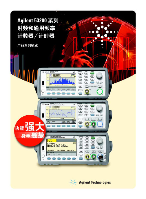
4.3 英寸(109.22 mm) 大型彩色图形显示屏, 将测试、运算和分析结果清晰的显示出了, 让工程师一目了然
● 数字显示
● 图形显示 - 显示趋势线、条形图和直方图 以及游标, 视图可以缩放以便您观察所需的 数据。使用游标, 您可以从趋势图和直方图 中读取特定的测量值。彩色极限线使您可以 自定义合格/不合格界限,当测量结果超过 设定定阈值后, 您可以从前面板上轻松看到。
更多样化的连通性
● LAN 接口,LXI-C ● USB 2.0 接口 ● U盘存储器插口 ● 可选 GPIB 接口 ● 支持便携工作的电池选件 ● 出色的时基精度和稳定性
更强大的测量功能 (53230A 的独特优势)
● 连续无间隙的测量 ● 调制域分析 (MDA) 的基本功能和时
间戳 ● 可选的脉冲微波测量
内置帮助系统可为您了解 所需功能提供快速指导
USB 存储器 端口可为 1 M 读数内部存储 器提供有益 补充
一般特征 预热时间 显示屏
用户界面和帮助语言 工作台尺寸 机架安装尺寸 重量 工作温度 电源 接口
电池技术 (选件 300) 包括的附件
所有型号 45 分钟 4.3 英寸 (109.22 mm) 高分辨率、高亮度彩色 TFT WQVGA (480 x 272) 显示屏, LED 背光 英文、德文、法文、日文、简体中文、韩文 261.1 mm 宽 x 103.8 mm 高 x 303.2mm 深 212.8 mm 宽 x 88.3 mm 高 x 272. 3 mm 深 (2U x 1/2 宽) 3.9 kg (8.6 磅), 包括全部选件 0°C 至 +55°C 100 V 至 240 V 通用输入; 50/60 Hz - 5% 至 +10%; 100 V -120 V; 400 Hz ± 10% LAN 接口, 符合 LXI-C 1.3 标准 USB 2.0 接口 (USB-TMC488 协议); GPIB 选件 400 内置锂离子电池, 包括集成的智能电池监视器和充电器 文档光盘, 其中包括用户指南、SCPI/ 程序员参考手册、编程实例、驱动程 序 (IVI-COM、LabView) 和 IO 程序库说明书 电源线, 2 m USB2.0 校准证书和 1 年期标准保修
莱埃尔电子有限公司产品说明:拉瓦雷特时间间隔计数器说明书

LAUREL ELECTRONICS, INC.Laureate™ Time Interval Meter Resolution to 0.2 µs for time of periodic events. Displays highly accurate rate based on 1 / time.Features•Times periodic events with width from 1 µs to 199.999 s•Display resolution to 0.2 µs•Rep rates to 250 kHz•Inputs from NPN or PNP proximity switches, contact closures, digital logic,magnetic pickups down to 12 mV, or AC inputs up to 250 Vac•Triggers on positive or negative pulse edges•Universal AC power, 85-264 Vac•Isolated 5, 10 or 24 Vdc excitation supply to power sensors•NEMA 4X, 1/8 DIN case•Optional serial I/O: Ethernet, USB, RS232, RS485, Ethernet-to-RS485 converter•Optional relay outputs: dual or quad relays, contact or solid state•Optional isolated analog output: 4-20 mA, 0-20 mA, 0-10V, -10 to +10V•Optional low voltage power: 10-48 Vdc or 12-32 Vac•Optional Extended Timer: features of standard timer plus rate based on 1/time DescriptionThe Laureate A-to-B Time Interval Meter can display pulsewidth or time delay between individual pulses to a resolution of0.2 µs. It can also display average pulse width or average timedelay between multiple pulses.Time interval is measured between inputs on channels A andB. Timing starts when a pulse is applied to Channel A (selectablepositive or negative edge), and ends when a pulse is applied toChannel B (selectable positive or negative edge). In case of asingle pulsed signal, the A and B inputs can be tied together. Apositive or negative slope may be selected to start timing, andthe opposite slope must be selected to stop timing. Timing isachieved by counting 5.5 MHz clock pulses. Multiple integral timeintervals are averaged over a gate time which is selectable from10 ms to 199.99 s and also controls the display update time.Time interval can be displayed in seconds, milliseconds, ormicroseconds with 6-digit resolution. In the typical application,time is displayed in milliseconds with 1 µs resolution. For timesless than 100 ms, display resolution down to 0.2 µs can beachieved by applying a multiplier of 10, moving the decimal pointby one position, and averaging many time intervals.Highly accurate rate can be displayed by taking the inverse oftime. Extensive arithmetic capabilities allow display inengineering units, such as meters/sec. Rate based on timerequires use of the Extended counter main board.The FR dual-channel signal conditioner board accepts inputsfrom proximity switches with PNP or NPN output, TTL or CMOSlogic, magnetic pickups, contact closures, and other signals from12 mV to 250 Vac. Jumper selections provide optimum operationfor different sensor types and noise conditions. A built-in isolated5, 10, or 24 Vdc excitation supply can power proximity switchesand other sensors, and eliminate the need for an external powersupply.Designed for system use. Optional plug-in boards includeEthernet and other serial communication boards, dual or quadrelay boards, and an isolated analog output board. Laureatesmay be powered from 85-264 Vac or optionally from 12-32 Vacor 10-48 Vdc. The display is available with red or green LEDs.The 1/8 DIN case meets NEMA 4X (IP65) specifications from thefront when panel mounted. Any setup functions and front panelkeys can be locked out for simplified usage and security. A built-in isolated 5, 10, or 24 Vdc excitation supply can power trans-ducers and eliminate the need for an external power supply.All power and signal connections are via UL / VDE / CSA ratedscrew clamp plugs.SpecificationsDisplayReadoutRangeIndicators6 LED digits, 7-segment, 14.2 mm (.56"), red or green-999999 to +999999Four LED lampsInputsTypes Grounding Minimum Signal Maximum Signal Noise Filter Contact Debounce AC, pulses from NPN, PNP transistors, contact closures, magnetic pickups. Common ground for channels A & BNine ranges from (-12 to +12 mV) to (+1.25 to +2.1V).250 Vac1 MHz, 30 kHz, 250 Hz (selectable)0, 3, 50 ms (selectable)Time Interval ModeTiming StartTiming StopPeriodic Timing Interval Gate TimeTime Before Zero Output Channel A pulse, + or - edges Channel B pulse, + or - edgesGate time + 30 ms + 0-2 time intervals Selectable 10 ms to 199.99 s Selectable 10 ms to 199.99 sResolution0 - 199.999 s 0 - 99.9999 s 0 - 9.99999 s 0 - .999999 s 0 - .099999 s 1 ms 100µs 10 µs 1 µs 0.2 µsAccuracyTime Base Span Tempco Long-term Drift Crystal calibrated to ±2 ppm ±1 ppm/°C (typ)±5 ppm/yearPowerVoltage, standard Voltage, optional Power frequency Power consumption (typical, base meter) Power isolation 85-264 Vac or 90-300 Vdc12-32 Vac or 10-48 VdcDC or 47-63 Hz1.2W @ 120 Vac, 1.5W @ 240 Vac, 1.3W @ 10 Vdc, 1.4W @ 20 Vdc, 1.55W @ 30 Vdc, 1.8W @ 40 Vdc,2.15W @ 48 Vdc250V rms working, 2.3 kV rms per 1 min testExcitation Output (standard)5 Vdc10 Vdc24 VdcOutput Isolation 5 Vdc ± 5%, 100 mA 10 Vdc ± 5%, 120 mA 24 Vdc ± 5%, 50 mA 50 Vdc to meter groundAnalog Output (optional)Output Levels Current compliance Voltage compliance Scaling Resolution Isolation 4-20 mA, 0-20 mA, 0-10V, -10 to +10V (single-output option) 4-20 mA, 0-20 mA, 0-10V (dual-output option)2 mA at 10V ( > 5 kΩ load)12V at 20 mA ( < 600Ω load)Zero and full scale adjustable from -99999 to +9999916 bits (0.0015% of full scale)250V rms working, 2.3 kV rms per 1 min test(dual analog outputs share the same ground)Relay Outputs (optional)Relay Types Current Ratings Output common Isolation 2 Form C contact relays or 4 Form A contact relays (NO)2 or 4 Form A, AC/DC solid state relays (NO)8A at 250 Vac or 24 Vdc for contact relays120 mA at 140 Vac or 180 Vdc for solid state relays Isolated commons for dual relays or each pair of quad relays 250V rms working, 2.3 kV rms per 1 min testSerial Data I/O (optional)Board SelectionsProtocols Data RatesDigital Addresses Isolation Ethernet, Ethernet-to-RS485 server, USB, USB-to-RS485 server, RS485 (dual RJ11), RS485 Modbus (dual RJ45), RS232 Modbus RTU, Modbus ASCII, Laurel ASCII protocol 300 to 19200 baud247 (Modbus), 31 (Laurel ASCII),250V rms working, 2.3 kV rms per 1 min testEnvironmental Operating Temperature Storage Temperature Relative Humidity Protection0°C to 55°C -40°C to 85°C95% at 40°C, non-condensingNEMA-4X (IP-65) when panel mountedElectrical ConnectionsMechanicalApplication ExamplesTime Interval Mode for Time DelayFor periodic pulses applied to A and B channels, time delays can be measured down to 0.2 µs resolution from the rising or falling edge of A to the rising or falling edge of B (selectable). Time Interval Mode for Pulse WidthThe width of periodic pulses (t1 or t2) can be measured by tying the A and B channels together. As for time delay, readings are averaged over a user-selectable gate time. Timing Process DynamicsThe start and stop pulses used for timing can be generated by the dual relay board in a Laureate panel meter or digital counter. For instance, the start and stop pulse edges can be created as temperature passes two alarm setpoints, or temperature cycles in a hysteresis control mode. Rate Based on 1 / TimeThe start and stop pulses used for timing can be generated by the dual relay board in a Laureate panel meter or digital counter. For instance, the start and stop pulse edges can be created as temperature passes two alarm setpoints, or temperature cycles in a hysteresis control mode.Replacing an Oscilloscope with a Laureate Time Interval MeterAn oscilloscope is great for viewing and timing pulses in a lab. However, in fixed installations where digital timing accuracy and control outputs are required, a low-cost Laureate time interval meter will be the instrument of choice. Resolution to 0.2 µs is feasible.Instrumenting a Pulsed Laser SystemSome of the many possibilities in instrumenting a pulsed laser system with Laureate dual-channelcounters: elapsed time, number of pulses, pulse width, pulse separation, duty cycle, and pulse rep rate.Ordering GuideCreate a model number in this format: L50000FR, IPCMain Board L5 Standard Main Board, Green LEDsL6 Standard Main Board, Red LEDsL7 Extended Main Board, Green LEDsL8 Extended Main Board, Red LEDsNote: Use of the Extended Main Board makes this counter also suitable for A-B time interval,frequency, rate, period, square root of rate, up or down total, arithmetic functions, simultaneousrate and total, phase, duty cycle, batching, and custom curve linearization.Power0 Isolated 85-264 Vac1 Isolated 12-32 Vac or 10-48 VdcRelay Output (isolated) 0 None1 Two 8A Contact Relays2 Two 120 mA Solid State Relays3 Four 8A Contact Relays4 Four 120 mA Solid State RelaysAnalog Output (isolated) 0 None1 Single isolated 4-20 mA, 0-20 mA, 0-10V, -10 to +10V2 Dual isolated 4-20 mA, 0-20 mA, 0-10VDigital Interface (isolated) 0 None1 RS2322 RS485 (dual RJ11 connectors)4 RS485 Modbus (dual RJ45 connectors)5 USB6 USB-to-RS485 converter7 Ethernet8 Ethernet-to-RS485 converterInput Type FR Dual-Channel Pulse Input Signal ConditionerAdd-on Options CBL01RJ11-to-DB9 cable. RJ11 to DB9. Connects RS232 ports of meter and PC.CBL02USB-to-DB9 adapter cable. Combination of CBL02 and CBL01 connects meter RS232port to PC USB port.CBL03-16-wire data cable, RJ11 to RJ11, 1 ft. Used to daisy chain meters via RS485.CBL03-76-wire data cable, RJ11 to RJ11, 7 ft. Used to daisy chain meters via RS485.CBL05USB cable, A-B. Connects USB ports of meter and PC.CBL06USB to RS485 adapter cable, half duplex, RJ11 to USB. Connects meter RS485 portto PC USB port.CASE1Benchtop laboratory case for one 1/8 DIN meterCASE2Benchtop laboratory case for two 1/8 DIN metersIPC Splash-proof coverBOX1NEMA-4 EnclosureBOX2NEMA-4 enclosure plus IPCBL Blank Lens without button padsNL Meter lens without button pads or Laurel logo。
Agilent 53131A 132A 181A 计数器技术资料

可使用。若与 53181A 同时购买可选的后面板端子时, 通道 1 可在计数器的前、后面板使用。在此条件下,后面 板连接的技术指标也适用于前面板连接。
老化率 (30 天后)
每天: 每月: 每年:
< 3 × 10⁻⁷
< 4 × 10⁻⁸ < 2 × 10⁻⁷
< 5 × 10⁻¹⁰ < 1.5 × 10⁻⁸
< 1 × 10⁻¹⁰ < 3 × 10⁻⁹ < 2 × 10⁻⁸
开机稳定度 时间 (30 分钟内)
< 2 × 10⁻⁷ 以 2 小时作参照
< 5 × 10⁻⁹ 以 24 小时作参照
Agilent 53131A/132A/181A 计数器 高性能、低价计数器 简化和加速了生产制造和研发的频率测量
产品综述
225 MHz 带宽 (可选 1.5, 3, 5, 12.4 GHz)
1 秒闸门时间时为 10 位或 12 位分 辨率
GPIB接口和IntuiLink连通性软件为 标准配置
高达200次/秒全格式化测量数据传 输率
选件 015(仅 53181A) 0.66ns - 10ns
选件 030
0.33ns - 10ns
选件 050
0.2ns - 5ns
选件 124
80ps - 5ns
频率比(53131A, 53132A, 53181A)
规定在各输入的全部信号范围测量
测量结果范围
10-10 至 1011
“自动”闸门时间 100ms
Agilent 53131A 132A 181A计数器说明书
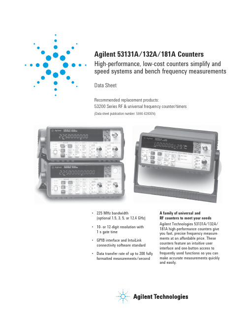
• 225 MHz bandwidth(optional 1.5, 3, 5, or 12.4 GHz)• 10- or 12-digit resolution with 1 s gate time • GPIB interface and IntuiLink connectivity software standard • Data transfer rate of up to 200 fully formatted measurements/secondAgilent 53131A/132A/181A CountersHigh-performance, low-cost counters simplify and speed systems and bench frequency measurementsData SheetRecommended replacement products:53200 Series RF & universal frequency counter/timers(Data sheet publication number: 5990-6283EN)A family of universal andRF counters to meet your needs Agilent Technologies 53131A/132A/181A high-performance counters give you fast, precise frequency measure-ments at an affordable price. These counters feature an intuitive user interface and one-button access to frequently used functions so you can make accurate measurements quickly and easily.Real-time digital signal processing technology is used to analyze data while simultaneously taking new read-ings, speeding measurement through-put. The technology, developed for Agilent’s high-end line of modulation domain analyzers, allows the counters to gather more data for each measure-ment, so you get higher-resolution measurements in a fraction of the time it takes other counters.The 53131A/132A/181A counters offer built-in statistics and math functions so you can scale measurements and simultaneously measure and track average, min/max and standard devia-tion. Automated limit testing lets you set upper and lower limits for any mea-surement. An analog display mode lets you see at a glance whether a mea-surement is within pass/fail limits. The counters flag out-of-limit conditions and can generate an output signal to trigger external devices when a limitis exceeded. For quick access to fre-quently used tests, a single keystroke recalls up to 20 different stored front-panel set-ups. For computer-controlled systemsapplications, each counter includesa standard GPIB interface with fullSCPI-compatible programmability anda data transfer rate of up to 200 fullyformatted measurements per second.The standard RS-232 talk-only interfaceprovides printer support or data trans-fer to a computer through a terminal-emulation program.Agilent 53131A universal counterThe two-channel 53131A counter offers10 digits per second of frequency/period resolution and a bandwidth of225 MHz. Time interval resolution isspecified at 500 ps. An optional thirdchannel provides frequency measure-ments up to 3 GHz, 5 GHz, or 12.4 GHz.Standard measurements include fre-quency, period, ratio, time interval,pulse width, rise/fall time, phaseangle, duty cycle, totalize, and peakvoltage.Agilent 53132A universal counterFor applications requiring higherresolution, the 53132A offers the samefeatures and functions as the 53131A,with up to 12 digits/sec frequency/period resolution and 150 ps timeinterval resolution. In addition, the53132A offers advanced arming modesfor time interval measurements.Agilent 53181A RF counterOptimized for RF applications, thesingle-channel 10 digit/s 53181Ameasures frequency, period and peakvoltage. A digit-blanking function letsyou easily eliminate unnecessary digitswhen you want to read measurementsquickly. For higher-frequency measure-ments, choose an optional secondchannel that provides measurementsup to 1.5 GHz, 3 GHz, 5 GHz, or 12.4 GHz.A self-guided shallow menu makes thiscounter exceptionally easy to use.Agilent IntuiLink provides easy access to the counter’s data from your PC The Agilent 53131A/132A/181A counters, capture precise frequencyand time measurements. IntuiLink software allows that data to be putto work easily. You work in a familiar environment at all times, using PC applications such as Microsoft Excel®or Word® to analyze, interpret, display, print, and document the data you get from the counter.It gives you the flexibility to configure and run tests from your PC making data gathering more convenient.Agilent IntuiLink lets you:• Configure tests, including measure-ment type, number of readings,measurement speed, and more.• Choose display modes from real-time strip chart, histogram, readout,and table mode.• Scale measurements data.• Copy captured data to otherprograms.Optional timebases offerincreased stabilityOptional timebases are availablefor 53131A/132A/181A counters toincrease measurement accuracy. Option010 provides a high stability oventimebase with aging of less than5 x 10-10 per day.1-year warrantyEach counter comes with operating,programming and service manuals,IntuiLink software, a power cord anda full 1-year warranty.Time BaseInternal time base stability (see graph 3 for timebase contribution of measurement error)Standard Medium oven High oven Ultra high oven(0° to 50°C) (Option 001) (Option 010) (Option 012 for 53132A only) Temperature stability (referenced to 25°C)< 5 x 10⁻⁶< 2 x 10⁻⁷< 2.5 x 10⁻⁹< 2.5 x 10⁻⁹Aging rate Per Day: < 4 x 10⁻⁸< 5 x 10⁻¹⁰< 1 x 10⁻¹⁰(after 30 days) Per Month: < 3 x 10⁻⁷ < 2 x 10⁻⁷< 1.5 x 10⁻⁸< 3 x 10⁻⁹Per Year: < 2 x 10⁻⁸Turn-on stability vs. time(in 30 minutes) < 2 x 10⁻⁷ < 5 x 10⁻⁹< 5 x 10⁻⁹referenced to 2 h referenced to 24 h referenced to 24 h Calibration Manual adjust Electronic Electronic ElectronicNote that power to the time base is maintained when the counter is placed in standby via the front panel switch. The internal fan will continue to operate when in standby to maintain long-term measurement reliability.Input specificationsChannel 1 & 2 (53131A, 53132A)1Channel 1 (53181A)Frequency rangedc coupled dc to 225 MHzac coupled 1 MHz to 225 MHz (50 Ω)30 Hz to 225 MHz (1 MΩ)FM tolerance 25%Voltage range and sensitivity (Sinusoid)2dc to 100 MHz 20 mVrms to ±5 V ac + dc 100 MHz 30 mVrms to ±5 V ac + dcto 200 MHz200 MHz 40 mVrms to ±5 V ac + dcto 225 MHz (all specified at 75 mVrmswith opt. rear connectors)3 Voltage range and sensitivity(Single-shot pulse)24.5 ns to 10 ns 100 mVpp to 10 Vpppulse width (150 mVpp with optionalrearconnectors)3>10 ns 50 mVpp to 10 Vpppulse width (100 mVpp with optionalrearconnectors)3Trigger level2Range ± 5.125 VAccuracy ± (15 mV + 1% of trigger level) Resolution 5mVDamage level50 Ω 5 Vrms0 to 3.5 kHz, 350 Vdc + ac pk1 MΩ3.5 kHz to 350 Vdc + ac pk linearly100 kHz, 1 MΩderated to 5 Vrms>100 kHz, 5 Vrms1 MΩ Input characteristicsChannel 1 & 2 (53131A, 53132A)1Channel 1 (53181A)Impedance 1 MΩ or 50 Ω1 MΩ 30 pFcapacitanceCoupling ac or dcLow-pass filter 100 kHz, switchable-20 dB at > 1 MHzInput Selectable between Low,sensitivity Medium,orHigh(default).Low is approximately 2xHighSensitivity.Trigger slope Positive or negativeAuto trigger levelRange 0 to 100% in 10% stepsFrequency > 100 HzInput amplitude> 100 mVpp(No amplitude modulation)AttenuatorVoltage range x10Trigger range x10Input Specifications4Channel 3 (53131A, 53132A)Channel 2 (53181A)Frequency rangeOption 015 100 MHz to 1.5 GHz(for 53181A (see Opt. 030 foronly) additionalspecs)Option 030 100 MHz to 3 GHzOption 050 200 MHz to 5 GHzOption 124 200 MHz to 12.4 GHzPower range and sensitivity (Sinusoid)Option 030 100 MHz to 2.7 GHz:-27 dBm to +19 dBm2.7 GHz to 3 GHz:-21 dBm to +13 dBmOption 050 200 MHz to 5 GHz:-23 dBm to +13 dBmOption 124 200 MHz to 12.4 GHz-23 dBm to +13 dBmDamage levelOption 030 5 VrmsOption 050 +25 dBmOption 124 +25 dBmCharacteristicsImpedance 50ΩCoupling ACVSWR <2.5:1External arm input specifications5Signal input rangeTTL compatibleTiming RestrictionsPulse width > 50 nsTransition time < 250 nsStart-to-stop time> 50 nsDamage level 10VrmsExternal arm input characteristics5Impedance 1kΩInput capacitance 17 pFStart/stop slope Positive or negativeExternal time base input specificationsVoltage range 200 mVrms to 10 VrmsDamage level 10 VrmsFrequency 1 MHz, 5 MHz, and 10 MHz(53132A 10 MHz only)Time base output specificationsOutput frequency 10 MHzVoltage > 1 Vpp into 50 Ω(centered around 0 V)1. Specifications and characteristics for Channels1 and2 are identical for both common andseparate configurations.2. Values shown are for X1 attenuator setting.Multiply all values by 10 (nominal) when usingthe X10 attenuator setting.3. When the 53131A or 53132A are ordered withthe optional rear terminals (Opt. 060), the channel1 and2 inputs are active on both front and rearof the counter. When the 53181A is ordered withthe optional rear terminal, the channel 1 input isactive on both front and rear of the counter. Forthis condition, specifications indicated for the rearconnections also apply to the front connections.4. When optional additional channels are orderedwith Opt. 060, refer to configuration table forOpt. 060 under ordering info on page 8. There isno degradation in specifications for this input,as applicable.5. Available for all measurements except peak volts.External arm is referred to as external gate forInstrument InputsFrequency (53131A, 53132A, 53181A) Channel 1 and 2 (53131A, 53132A)Channel 1 (53181A)Range 0.1 Hz to 225 MHzChannel 3 (53131A, 53132A)Channel 2 (53181A)Option 015 100 MHz to 1.5 GHz(53181 A only)Option 030 100 MHz to 3 GHzOption 050 200 MHz to 5 GHzOption 124 200 MHz to 12.4 GHz (Period 2 or 3 selectable via GPIB only)Period (53131A, 53132A, 53181A) Channel 1 and 2 (53131A, 53132A)Channel 1 (53181A)Range 4.44 ns to 10 sChannel 3 (53131A, 53132A)Channel 2 (53181A)Option 015 0.66 ns to 10 ns(53181A only)Option 030 0.33 ns to 10 nsOption 050 0.2 ns to 5 nsOption 124 80 ps to 5 nsFrequency ratio (53131A, 53132A, 53181A) Measurement is specified over the full signal range of each input.Results range 10-10 to 1011“Auto” gate time 100 msTime interval (53131A, 53132A) Measurement is specified over the full signal ranges6 of Channels 1 and 2.Results range -1 ns to 105 sLSD 500 ps (53131A)/150 ps(53132A)Phase (53131A, 53132A)Measurement is specified over thefull signal range of Channels 1 and 2.Results range -180° to +360°Duty cycle (53131A, 53132A)Measurement is specified over the fullsignal range of Channel 1. However, both thepositive and negative pulse widths must begreater than 4 ns.Results range 0 to 1 (e.g. 50% duty cyclewould be displayed as .5)Rise/fall time (53131A, 53132A)Measurement is specified over the full signalranges of Channel 1. The interval between theend of one edge and start of a similar edgemust be greater than 4 ns.Edge selection Positive or negativeTrigger D efault setting is auto triggerat 10% and 90%Results range 5 ns to 105 sLSD 500 ps (53131A)/150 ps(53132A)Pulse width (53131A, 53132A)Measurement is specified over the full signalrange of Channel 1. The width of the opposingpulse must be greater than 4 ns.Pulse selection Positive or negativeTrigger D efault setting is auto triggerat 50%Results range 5 ns to 105 sLSD 500 ps (53131A)/150 ps(53132A)Totalize (53131A, 53132A)Measurement is specified over thefull signal range of Channel 1.Results range 0 to 1015Resolution ± 1 countPeak volts (53131A, 53132A, 53181A)Measurement is specified on Channels 1 and 2for dc signals; or for ac signals of frequenciesbetween 100 Hz and 30 MHz with peak-to-peakamplitude greater than 100 mV.Results range -5.1 V to +5.1 VResolution 10mVPeak volts systematic uncertaintyfor ac signals: 25 mV + 10% of Vfor dc signals: 25 mV + 2% of VUse of the input attenuator multiplies allvoltage specifications (input range, resultsrange, resolution and systematic uncertainty)by a nominal factor of 10.Gate timeAuto mode, or 1 ms to 1000 sMeasurement throughputGPIB ASCII 200 measurements/s (maximum)Measurement armingStart Free run, manual, or externalmeasurementStop Continuous, single, external,measurement or timedTime interval 100 µs to 10 s (53131A)Delayed 100 ns to 10 s (53132A)armingArming modes(Note that not all arming modes are availablefor every measurement function.)5. Available for all measurements except peak volts.External arm is referred to as external gate for somemeasurements.6. See specifications for pulse width and rise/fall timemeasurements for additional restrictions on signaltiming characteristics.Measurement SpecificationsAuto arming: Measurements are initiated immediately and acquired as fast as possible, using a minimum number of signal edges. Timed arming: The duration of the measurement is internally timed to a user-specified value (also known as the “gate time”).Digits arming: Measurements are performedto the requested resolution (number of digits) through automatic selection of the acquisition time.External arming: An edge on the external arm Input enables the start of each measurement. Auto arming, timed arming modes or another edge on the external arm input may be used to complete the measurement.Time interval delayed arming: For time intervalmeasurements, the stop trigger condition isinhibited for a user-specified time following thestart trigger. The 53132A offers advanced timeinterval arming capabilities including use of userspecified time or Channel 2 events to delay bothstart and stop triggers.Measurement limitsLimit checking: The measurement value ischecked against user-specified limits at theend of each measurement.Display modes: The measurement result maybe displayed as either the traditional numericvalue or graphically as an asterisk movingbetween two vertical bars.Out-of-limits Indications:• The limits annunciator will light on the frontpanel display.• The instrument will generate an SRQ ifenabled via GPIB.• The limits hardware signal provided via theRS-232 connector will go low for the durationof the out-of-limit condition.• If the analog display mode is enabled, theasterisk appears outside the vertical bars,which define the upper and lower limits.Input signal frequency or timeGraph 6:Trigger level timing error(Level setting error andinput hysteresis)7. Graphs 1, 2, 4 and 5 do not reflect the effects oftrigger error. To place an upper bound on the added effect of this error term, determine the frequencyerror from the appropriate graph and add a trigger error term as follows:T r i g g e r e r r o r p e r t r i g g e r p o i n tAvailable statisticsM ean, Minimum, Maximum, Standard DeviationNumber of measurements 2 to 1,000,000. Statistics may be collected on all measurements or on only those which are between the limit bands. When the limits function is used in conjunction with statistics, N (number of measurements) refers to the number of in-limit measurements. In general, measurement resolution will improve in proportion to N,up to the numerical processing limits ofthe instrument.MeasurementsStatistics may be collected for all measurementsexcept peak volts and totalize.Measurement Statistics General Information1112Ordering Information/find/countersAgilent Email Updates/find/emailupdates Get the latest information on the products and applications you select.AdvancedTCA ® Extensions for Instrumentation and Test (AXIe) is an open standard that extends the AdvancedTCA for general purpose and semiconductor test. Agilent is a founding member of the AXIe consortium.LAN eXtensions for Instruments puts the power of Ethernet and the Web inside your test systems. Agilent is a founding member of the LXI consortium.PCI eXtensions for Instrumentation (PXI) modular instrumentation delivers a rugged, PC-based high-performance measurement and automation system.Agilent Channel Partners/find/channelpartners Get the best of both worlds: Agilent’s measurement expertise and product breadth, combined with channel partner convenience.For more information on AgilentTechnologies’ products, applications or services, please contact your local Agilent office. The complete list is available at:/find/contactus Americas Canada (877) 894 4414Brazil (11) 4197 3500Mexico01800 5064 800United States(800) 829 4444Asia Pacific Australia 1 800 629 485China 800 810 0189Hong Kong 800 938 693India 1 800 112 929Japan 0120 (421) 345Korea 080 769 0800Malaysia 1 800 888 848Singapore 180****8100Taiwan 0800 047 866Other AP Countries (65) 375 8100Europe & Middle East Belgium 32 (0) 2 404 93 40Denmark 45 70 13 15 15Finland 358 (0) 10 855 2100France 0825 010 700**0.125 €/minuteGermany 49 (0) 7031 464 6333Ireland 1890 924 204Israel 972-3-9288-504/544Italy 39 02 92 60 8484Netherlands 31 (0) 20 547 2111Spain 34 (91) 631 3300Sweden 0200-88 22 55United Kingdom 44 (0) 131 452 0200For other unlisted countries:/find/contactusRevised: June 8, 2011Product specifications and descriptions in this document subject to change without notice.© Agilent Technologies, Inc. 2006, 2011Published in USA, November 8, 20115967-6039ENAgilent Advantage Services is committed to your success throughout your equip-ment’s lifetime. To keep you competitive, we continually invest in tools andprocesses that speed up calibration and repair and reduce your cost of ownership. You can also use Infoline Web Services to manage equipment and services more effectively. By sharing our measurement and service expertise, we help you create the products that change our world./quality/find/advantageservices。
时间间隔计数器Agilent53132A手册

通道1和2(53131A, 53132A);通道1(53181A)
范围
0.1Hz - 225MHz
通道 3(53131A, 53132A);通道 2(53181A)
选件 015(仅 53181A) 100MHz - 1.5GHz
选件 030
100MHz - 3GHz
选件 050
200MHz - 5GHz
) tacc
× 频率或周期
Gate Time
典型值 最坏情况
53131A tacc 350 ps 1.25 ns
53132A tacc 100 ps 500 ps
53181A tacc 350 ps 1.25 ns
触发:默认设置为 50% 处的自动触发
对于时间或位数同步
( ) LCD 显示:
2 √2 x tres Gate Time x √Number of Samples
阻抗
1MΩ 或 50Ω
1MΩ 电容
30pF
耦合
交流或直流
低通滤波器
100kHz,可切换,
>1MHz 为 -20dB
输入灵敏度
可选低、中、高(默认)。
低近似为 2 ×高灵敏度。
1. 通道 1 和 2 的指标和特性适用于相同的和单独的配置。 2. 所示为 X1 衰减器设置时的值。当使用 X10 衰减器设置
5. 适用于除峰电压外的所有测量。对某些测量,外同步以 外闸门为参照。
对于自动或外同步: (和信号<100Hz,使用定时同步)
( ) LCD显示:
tres Gate Time
× 频率或周期
( ) √ RMS 分辨率:
t
2 res
+
频率计
频率计一、频率计的基本原理:频率计又称为频率计数器,是一种专门对被测信号频率进行测量的电子测量仪器。
其最基本的工作原理为:当被测信号在特定时间段T内的周期个数为N时,则被测信号的频率f=N/T(如右图所示)。
频率计主要由四个部分构成:时基(T)电路、输入电路、计数显示电路以及控制电路。
在一个测量周期过程中,被测周期信号在输入电路中经过放大、整形、微分操作之后形成特定周期的窄脉冲,送到主门的一个输入端。
主门的另外一个输入端为时基电路产生电路产生的闸门脉冲。
在闸门脉冲开启主门的期间,特定周期的窄脉冲才能通过主门,从而进入计数器进行计数,计数器的显示电路则用来显示被测信号的频率值,内部控制电路则用来完成各种测量功能之间的切换并实现测量设置。
二、频率计的应用范围:在传统的电子测量仪器中,示波器在进行频率测量时测量精度较低,误差较大。
频谱仪可以准确的测量频率并显示被测信号的频谱,但测量速度较慢,无法实时快速的跟踪捕捉到被测信号频率的变化。
正是由于频率计能够快速准确的捕捉到被测信号频率的变化,因此,频率计拥有非常广泛的应用范围。
在传统的生产制造企业中,频率计被广泛的应用在产线的生产测试中。
频率计能够快速的捕捉到晶体振荡器输出频率的变化,用户通过使用频率计能够迅速的发现有故障的晶振产品,确保产品质量。
在计量实验室中,频率计被用来对各种电子测量设备的本地振荡器进行校准。
在无线通讯测试中,频率计既可以被用来对无线通讯基站的主时钟进行校准,还可以被用来对无线电台的跳频信号和频率调制信号进行分析。
三、频率计厂商介绍:目前,市场上的频率计厂家可分为三类:中国大陆厂家、中国台湾厂家、欧美厂家。
其中,欧美频率计厂家所占有的市场份额最大。
欧美频率计厂家主要有:Pendulum Instruments 和Agilent科技。
Pendulum Instruments 公司是一家瑞典公司,总部位于瑞典首都斯德哥尔摩。
Pendulum 公司源于Philips公司的时间、频率部门,在时间频率测量领域具有40多年的研发生产经历。
基于FPGA和数字法的IRIG-B(AC)码的解码设计
基于FPGA和数字法的IRIG-B(AC)码的解码设计张贵军【摘要】In order to solve the problem of low decoding accuracy and low stability of IRIG-B(AC)codes,a high precision and high stability B(AC)code decoding design method is proposed.The method uses the FPGA and ADS8365 chip,and adopts the digital circuit decoding method of multiplier and digital filter,and the time information of the B(AC)code is decoded and the second pulse signal is output.After experimental verification,the system can be work for a long time,no error output time information and deviation in subtle level of the second pulse signal,and meet a variety of application areas of IRIG-B(AC)code timing requirements.%为了解决IRIG-B(AC)码解码精度低、稳定性不高的问题,提出了一种高精度、高稳定性的B(AC)码解码设计方法.使用FPGA和ADS8365芯片,采取乘法器和数字滤波器相结合的数字电路解码方式,解调出B(AC)码中的时间信息并输出秒脉冲信号.经试验验证,系统可长时间、无误码地输出时间信息以及偏差在微妙级内的秒脉冲信号,能够满足各种应用场所对IRIG-B(AC)码授时的要求.【期刊名称】《电子器件》【年(卷),期】2017(040)004【总页数】6页(P856-861)【关键词】B(AC)码解码;A/D转换;数字解码电路;秒脉冲;高精度【作者】张贵军【作者单位】山西财政税务专科学校,太原 030024【正文语种】中文【中图分类】TN787随着国家北斗卫星计划的不断成功实施,航天科技的不断发展,时间同步得到了越来越广泛的应用。
数字式时间间隔测量仪使用教程
数字式时间间隔测量仪使用教程关键词:数字式时间间隔测量仪,时间间隔测量装置,时间间隔测量设备一、时间间隔测量装置是什么,可以测什么?时间间隔测量仪是根据《时间间隔测量仪》检定规程设计的一款精密时间差测量仪器。
时间间隔的测量分两种情况,无论是下面哪种时间间隔测量都可以使用西安同步生产的SYN5605A型数字式时间间隔测量仪。
两种情况分别如下:(1)同一信号波形上两个不同点之间的时间间隔的测量,例如,脉冲宽度的测量、脉冲重复周期的测量。
(2)两个信号波形上两点之间的时间间隔测量,例如,时延的测量、相位差的测量等。
二、如何用数字式时间间隔测量设备来测时间间隔(1)接线:将待测信号接入SYN5605A型时间间隔测量仪器主机通道1 或通道1和通道2(2)选接哪个通道:如果测的是一个脉冲信号的周期或脉宽,接通道1;如果测的是2个信号的延迟,分别接通道1和通道2。
(3)选择通道模式单通道是指触发信号起始为通道 1,停止也为通道 1双通道是通道1和通道2同时测量(4)选择测量模式单次测量就是测一次连续测量就是一直测量(5)设置触发电平通过数字键盘设置触发电平,触发电平设置范围-12V~+12V (6)选择触发方式选择起始和结束沿,分为上升沿和下降沿(7)点击启动即可。
三、使用注意事项:(1)时间间隔测量过程中如需更高测试分辨力则可以根据测试需要选择“高精度模式”,“长量程模式”为普通测量显示分辨力。
(2)设备内置有高精度恒温晶振,出厂频率偏差为≤3E-8。
(3)输出1路10MHz信号,出厂频率偏差为≤3E-8,可以做高精度10MHz信号源使用。
(4)设计有10MHz外参考信号输入,可以外接铷钟或铯钟输出的10Mhz信号作为高准确度参考源从而大幅度提高测量精度。
(5)通讯接口为串口232,输出测量结果及设置状态。
(6)该款时间间隔测量仪除了时间间隔测量功能,还设计有边沿测试和脉冲计数功能。
边沿测试就是测上升沿或下降沿的时间。
53132A频率计
HP(agilent) 53131A 53132A频率计:技术指标:频率范围:DC - 3GHz老化率:3 * 10(-7)/月时间间隔测量范围:500ps - 1000s显示位数:10位输入信号灵敏度:20mV其他说明:型号: HP53131A产品说明:·高精度频率测量到225MHz(通过选件可达1.5、3.5或12.4GHz)·53131A和53132A高精度的时间间隔测量·具有菜单结构的直观的用户界面·标准的GPIB,具有每秒200个全格式化测量数据传送速率:RS-232(只讲)·极限测试能力·53181A 10位数字/秒·53131A 10位数字/秒和500ps的分辨率·53132A 12位数字/秒和150ps的分辨率全系列高性能RF和通用计数器价格有让,性能不减53131A/132A/181A高性能计数器提供十分优越的价格和性能,结构牢固,重量经,使用方便,具有完整的测量装置,广泛的分析功能,良好的可靠性,高的测量速率和数据传送速率。
这些仪器采用实时数字信号处理技术,在分析数据的同时获取新的读数,加速测量吞吐量。
这种为GPIB高层次调制域分析仪系列开发的技术,使计数器能够在每次测量聚集更多的数据,所以可得到更高分辨率的测量,所用时间仅是传统的倒数计数器的几分之一。
强大的分析能力53131A/132A/181A计数器都具有内置的统计和数学功能,所以,你可以给测量定标,同时测量和跟踪平均值、最大和最小值和标准偏差。
自动的极限测试使您能够设置任何一种测量的上限和下限。
当测量结果因超出此范围而失败时,计数器就记录了超出范围的状态,提醒操作者并产生一输出信号来触发外部设备或停止测试,模拟显示方式一步即完成极限测试,它让您一目了然地观察通过/失败的极限中的测量结果是否失败了。
高速自动测试能力对计算机控制系统的应用,每种Agilent 53100 系列计数器包括一标准的GPIB接口,其数据传送速率优于每秒200个全格式化测量数据。
- 1、下载文档前请自行甄别文档内容的完整性,平台不提供额外的编辑、内容补充、找答案等附加服务。
- 2、"仅部分预览"的文档,不可在线预览部分如存在完整性等问题,可反馈申请退款(可完整预览的文档不适用该条件!)。
- 3、如文档侵犯您的权益,请联系客服反馈,我们会尽快为您处理(人工客服工作时间:9:00-18:30)。
53131A tres 53132A tres 53181A tres
650 ps
200 ps
650 ps
见最坏情况分辨率性能图
对于自动同步:闸门时间 = N / 频率
这里 N = 1,对于标准通道频率 <1MHz 4,对于标准通道频率 >1MHz 128,对于可选通道
( 系统不确定度: ±Time Base Error ±
Agilent IntuiLink 提供从您 PC 至
它为您提供从 PC 配置和运行测试
计数器数据的容易访问
的灵活性,使数据的收集更为便利。
Agilent 53131A/132A/181A 计数器 捕获精确的频率和时间测量结果。 IntuiLink 软件使获取数据的工作容易。 您始终在熟悉的环境中工作,使用 Microsoft Excel® 或 Word® 这类 PC 应用 程序对取自计数器的数据进行分析、解 释、显示、打印和生成文档。
也可采用BenchLink Meter软件,这 是独立的应用软件。
BenchLink Meter 使您能: 配置测试,包括测量类型、读数的数 目、测量速度及其它。 选择显示模式,包括实时条图,直方 图,数字读出和表格模式。 标度测量数据。 把捕获数据复制到其它程序。
提供增加稳定度的可选时基
53131A/132A/181A 计数器能用 可选时基增加测量精度。选件 010 是 高稳定度的恒温槽时基,老化率<5 × 10⁻¹⁰/ 天。
满足您需要的通用和射频计数器 家族
Agilent 53131A/132A/181A 高性能 计数器以优异的价格提供快速和精确的 频率测量。这些计数器带有直观的用户 界面和对常用功能的单键访问,使您能 快速和容易地进行精确测量。
实时数字信号处理技术在获取新读 数的同时分析数据,以得到更高的测量 吞吐率。这是Agilent为高端调制域分析 仪开发的技术,能让计数器在每次测量 中获得更多的数据,用其它计数器几分 之一的时间获得高分辨率的测量结果。
特性
阻抗 耦合 VSWR
5Vrms +25Vrms +25Vrms
50Ω AC < 2.5:1
外同步输入特性 5
信号输入范围
TTL 兼容
定时限制
脉冲宽度 跃变时间 开始—停止时间
> 50ns < 250ns > 50ns
损坏电平
10Vrms
外同步输入特性 6 阻抗 输入电容 开始 / 停止斜率
1kΩ 17pF 正或负
Agilent 53181A RF 计数器
53181A 是单通道的 10 位 / 秒射频 计数器,可测量频率、周期和峰电压。在 需要快速读取测量结果时,您可用数字 消稳功能容易地去掉不必要的显示位。 对于高频测量,可选的第 2 通道提供高 达 1.5GHz, 3GHz, 5GHz 或 12.4GHz. 测量。自引导菜单使该计数器的操作极 为方便。
对于受计算机控制的系统应用, 每台计数器都包括具有完全 SCPI 兼容 编程能力的 GPIB 接口,以及高达 200 次 / 秒的全格式测量数据传输率。标准 RS-232 只读接口提供打印机支持,或通 过终端仿真程序至计算机的数据传输。
Agilent 53131A 通用计数器
双通道 53131A 通用计数器提供 10 位/秒的频率/周期分辨率和225MHz带 宽。时间间隔分辨率为 500ps。可选的第 3通道提供高达3GHz, 5GHz或12.4GHz 的频率测量。标准测量包括频率、周 期、比率、时间间隔、脉冲宽度、上
) tacc
× 频率或周期
Gate Time
典型值 最坏情况
53131A tacc 350 ps 1.25 ns
53132A tacc 100 ps 500 ps
53181A tacc 350 ps 1.25 ns
触发:默认设置为 50% 处的自动触发
对于时间或位数同步
( ) LCD 显示:
2 √2 x tres Gate Time x √Number of Samples
通道1和2(53131A, 53132A);通道1(53181A)
范围
0.1Hz - 225MHz
通道 3(53131A, 53132A);通道 2(53181A)
选件 015(仅 53181A) 100MHz - 1.5GHz
选件 030
100MHz - 3GHz
选件 050
200MHz - 5GHz
阻抗
1MΩ 或 50Ω
1MΩ 电容
30pF
耦合
交流或直流
低通滤波器
100kHz,可切换,
>1MHz 为 -20dB
输入灵敏度
可选低、中、高(默认)。
低近似为 2 ×高灵敏度。
1. 通道 1 和 2 的指标和特性适用于相同的和单独的配置。 2. 所示为 X1 衰减器设置时的值。当使用 X10 衰减器设置
53131A/132A/181A 计数器提供内 置的统计和数学运算功能,因此您能标 度测量结果,同时测量和跟踪平均值、 最小值 / 最大值和标准偏差。自动极限 测试使您能为任何测量设置上限和下 限。您能通过模拟显示模式方便地看到
测量结果是否在通过 / 失败极限内。在 超出极限时,计数器能标志超出极限的 条件,产生触发外部装置的输出信号。 为快速访问常用的测试,还能通过一次 键击调用所保存的多达 20 种不同前面 板设置。
时,所有值乘以 10(标称值)。 3. 若与 53131A 或 53132A 同时购买可选的后面板端子 (选件 060)时,通道 1 和 2 在计数器的前、后面板均
可使用。若与 53181A 同时购买可选的后面板端子时, 通道 1 可在计数器的前、后面板使用。在此条件下,后面 板连接的技术指标也适用于前面板连接。
< 5 × 10⁻⁹ 以 24 小时作参照
校准
手动调节
电校准
电校准
电校准
注意当计数器通过前面板开关处于 standby 时,要保持对时基的供电。standby 时的内部风扇将继续工作,以保持长期测量可靠性。
仪器输入
输入特性 通道 1 和 2(53131A, 53132A)1 通道 1(53181A)
(仅对于 53181A) (其它指标见选件 030)
选件 030
100MHz - 3GHz
选件 050
200MHz - 5GHz
选件 124
200MHz - 12.4GHz
功率范围和灵敏度(正弦)
选件 030
选件 050 选件 124
100MHz - 2.7GHz, -27dBm - +19dBm
2.7GHz - 3GHz, -21dBm - +13dBm
Agilent 53131A/132A/181A 计数器 高性能、低价计数器 简化和加速了生产制造和研发的频率测量
产品综述
225 MHz 带宽 (可选 1.5, 3, 5, 12.4 GHz)
1 秒闸门时间时为 10 位或 12 位分 辨率
GPIB接口和IntuiLink连通性软件为 标准配置
高达200次/秒全格式化测量数据传 输率
+
t jitter
Gate Time
× 频率或周期
( ) RMS 分辨率:
√ 4 x
t
2 res
+
(2
x
Trigger
Error
2)
Gate Time x √Number of Samples
+
t jitter
Gate Time
× 频率或周期
(见图 2)
53131A/181A
典型值
tres 500 ps
触发斜率 自动触发电平 范围 频率 输入幅度
衰减器 电压范围 触发范围
正或负
0 - 100%,以 10% 步进 > 100Hz > 100mVpp (无幅度调制)
× 10 × 10
输入特性 4 通道 3(53131A, 53132A) 通道 2(53181A) 频率范围
选件 015
100MHz - 1.5GHz
升 / 下降时间、相角、占空比、总和 和峰电压。
Agilent 53132A 通用计数器
对于要求更高分辨率的应用, 53132A 提供与 53131A 相同的特性和功 能,具有 12 位 / 秒的频率 / 周期分辨率 和 150ps 的时间间隔分辨率。此外, 53132A 还为时间间隔测量提供先进的 外同步工作模式。
5. 适用于除峰电压外的所有测量。对某些测量,外同步以 外闸门为参照。
对于自动或外同步: (和信号<100Hz,使用定时同步)
( ) LCD显示:
tres Gate Time
× 频率或周期
( ) √ RMS 分辨率:
t
2 res
+
2
x
Trigger
Error
2)
× 频率或周期
Gate Time
典型值
选件 015(仅 53181A) 0.66ns - 10ns
选件 030
0.33ns - 10ns
选件 050
0.2ns - 5ns
选件 124
80ps - 5ns
频率比(53131A, 53132A, 53181A)
规定在各输入的全部信号范围测量
测量结果范围
10-10 至 1011
“自动”闸门时间 100ms
时基
内时基稳定度(时间对测量误差的影响见图 3)
标准 (00C-500C)
中稳定恒温槽 (选件 001)
高稳定恒温槽 (选件 010)
超高稳定恒温槽 (选件 012,仅适用于 53132A)