Miperf操作指导
MapInfo插件MIPT使用说明和教程
MAPINFO插件MIPI操作手册目前全省使用的频率规划插件有Easywork和MIPT,这里以MIPT为例介绍该插件的常用功能和基站电子地图的生成。
1 生成基站电子地图MIPT生成电子地图需要的原始文件有sitedata.txt和neighbourdata.txt,其中sitedata用于生成基站的扇区图,neighbourdata用于生成相邻小区表。
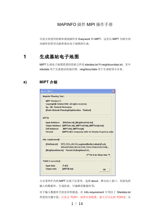
a) MIPT介绍点击菜单栏内的MIPT出现下拉菜单,选择about,弹出如上窗口,里面包括输入的数据库、生成的表、可编辑的数据库等;对于输入数据库字段也有所描述,在Info.requirement中列出了Sitedata.txt所需的关键字段,注意无TCH1,按照目前配置,最大可以达到TCH12,关键字段的顺序无要求。
数据库如下,显示为红色的是关键字段,必须有的,其它的如基站名称等可以根据需要自行添加:NeighbourData.txt相对简单些,只要小区和相邻小区的CI即可。
字段分别为ParentCell和NeighbourCell。
MIPT也可以对TOM路测文件进行分析,功能与BIGS类似,这里就不详细介绍了,感兴趣的同事可以自己研究一下。
b) 导入基站数据假设我们已经如上表的格式生成了Sitedata.txt和NeighbourData.txt,现在要生成基站电子地图,首先点MIPT,选择下拉菜单中的Import Database弹出窗口选择确定,如果不需要相邻小区,可以将Neighbourdata前对号去掉:依次导入SiteData和Neighbourdata:导入之后,右下角消息窗口显示如下:维护表结构:选择MIPTsite,点击确定后,将CELL字段的类型从“整型”修改为“字符型”,宽度设置为“5”,宽度和CELL最大位数有关。
注意,这里CELL的值与小区CI相等,需要将字段类型从整型调整为字符型,否则生成地图时会出错。
同样选择MIPTneigh,点击确定,将ParentCell和NeighbourCell字段修改为“字符型”,邻区查找是按照CELL字段进行索引,若字段类型不一致,查找相邻小区时无法查到邻区。
PiFace Digital 2 用户指南说明书

PIFACE DIGITAL 2For Raspberry Pi® - Getting startedConnect to the real world in minutes, with the most popular interfaceboard for Raspberry Pi®.PiFace™ Digital 2For step by step help and ideas for projects visit: /guides/This guide applies to PiFace™ Digital 2 which is used with the Raspberry Pi® models A+ and B+ (40 pin connector).PiFace™ Digital 2 is one of the quickest and easiest way to connect your Raspberry Pi® to the real world. Follow this guide and your Raspberry Pi® will be reacting to switches and controlling motors and lights in less than ten minutes!The original PiFace™ Digital interface board fits the original Raspberry Pi® models A and B. PiFace™ Digital 2 has been redesigned to fit the Raspberry Pi® models A+ and B+. Product highlightsTypical applications:●Education●Home/Industrial automation●Security monitoring●Internet of Things gateway●Remote monitoring●Hobbyist projects and games●I/O expander●User interface for systemsFeatures:● 2 changeover relays● 4 switches●8 digital inputs●8 open-collector outputs●8 LED indicators●Easy to program in Python, Scratch and C●Graphical emulatorTechnical specifications:●Changeover relays, 20V 5A switching max● 1.5mm screw terminal hole size●Operating Temp -40° to 85°Fitting instructionsWarnings●Ensure that no power is supplied to Raspberry Pi®, or PiFace™ Digital 2 boardswhen plugging or unplugging.PiFace™ Digital 2 sits neatly above the Raspberry Pi® and connects using the expansion connector. Take care to ensure all expansion pins are lined up with the holes on the PiFace™ Digital 2 socket. Check the alignment for left and right, and front and back before pushing down and never force the boards together if they don’t slide smoothly.Tour of hardwarePiFace™ Digital 2Hardware features Input portsThe 8 green screw terminals are inputs and used to detect if a switch or contact is open or closed. An input will register when it is connected to GND. The inputs are labelled on the underside of the board.The four switches, labelled S0 to S3, are connected in parallel to the first four (0-3) inputs.Example connection of a buttonTo wire up an external button connect the input pin of PiFace™ Digital 2 to one contact on the button and another wire from GND on PiFace™ Digital 2 to the other switch contact. Check your button’s datasheet to see which pins should be wired up.Output portsThe 8 orange screw terminals are open-collector (see below for more details) outputs used to control external components such as LEDs, lights or motors and are labelled on the underside of the board.LED indicationThe onboard LEDs can be used to show the status of an application running on the Raspberry Pi® without any additional components. They are also useful for debugging circuits and code to confirm intended output state.Example connection of outputTo wire up an external LED connect the anode (longer leg of the LED) to the 5V screw terminal. Connect the other leg, via a resistor (typically 330 ohm for most LEDs), to an output terminal. When you enable the output, PiFace™ Digital 2 allows current from the 5V supply to flow to ground through the LED which causes it to light up.example connection of a bulb and an LEDOpen-collectorsThe 8 outputs on PiFace™ Digital 2 are open-collector outputs, which can be used to control devices such as lights, motors or relays (which may require different voltages). Because the outputs are open-collector, they do not output any voltage, instead they enable or disable current to flow to ground. This gives greater flexibility as the outputs can operate at different voltages (since the PiFace™ Digital 2 doesn’t supply the voltage). Note: If the outputs are to be used for devices that operate at greater than 5V then jumpers must be set appropriately to avoid damage. For example disconnect jumpers JP4, JP5, JP6 and JP7.Relay outputsPiFace™ Digital 2 has two changeover relays in parallel with the first two outputs. Each relay is connected to three black screw terminals. The pins’ functions are shown in the diagram below and are labelled on the underside of the PiFace™ Digital 2.●NC - N ormally C losed contact●CO - CO mmon contact●NO - N ormally O pen contactThe NC and CO contacts are electrically connected until the relay is activated, at which point CO changes over to be connected to NO.The relays may be disabled by removing the appropriate jumper (JP5 and JP6) as detailed in Jumper settings.example connectionPower connectionsPiFace™ Digital 2 requires 3.3V to supply the integrated circuit (which requires negligible current), which it always takes from the Raspberry Pi®. The relays and LEDs require 5V to operate.PiFace™ Digital 2’s 5V can be configured to be supplied (as detailed below in Jumper settings)●Independently from the Raspberry Pi® via the power screw terminals●From the Raspberry Pi®’s 5V●Via the power screw terminals, and used to power the Raspberry Pi®Warning: Never have separate power supplies for both the Raspberry Pi® and PiFace™ Digital 2, when the power jumper is connected.Note: As discussed in the Output ports section PiFace™ Digital 2 does not supply power on its open-collector output pins or relay contacts!The top 3 set of terminals on the right of the board is used to supply or take power, with the top pin being 5V and bottom two ground. In many applications these do not need to be connected to anything, as the PiFace™ Digital 2 will be powered by the Raspberry Pi®.Using multiple PiFace™ Digital 2 interfacesMore inputs and outputs can be provided by stacking multiple PiFace™ Digital 2 boards using an appropriate connector (e.g. PiFace™ Rack or PiFace™ Shim). To distinguish between interfaces a different address must be set (see section Jumpers).JumpersIn most use cases all the jumpers can be left in place.Address jumpersJP1 and JP2 set the address of the board to enable multiple boards to be used together. The default is board address 0, indicated by the white lines printed next to each address jumper.PiFace™ Digital 2 address jumpersAddress Binary Address JP2 position JP1 position0001-21-21011-22-32102-31-23112-32-3JP1 controls the least significant bit of the address, and JP2 the most significant bit. Power share jumperJP3 selects whether the PiFace™ Digital 2 shares the same power source as the Raspberry Pi®. This supply can be either provided through the Raspberry Pi®’s MicroUSB connector, or from an external supply provided through PiFace™ Digital 2’s 5V and GND power screw terminals. With the jumper connected, the Raspberry Pi® and PiFace™ Digital 2 will share a single power supply. Disconnected, they will each need to be powered separately.Warning: Never use separate power supplies for both the Raspberry Pi® andPiFace™ Digital 2, when this jumper is connected.Snubber diodes jumperJP4 connects the snubber diodes from the ULN2803A to 5V (snubber diodes protect the driving transistors from the high voltages that occur when a coil, e.g. a relay, turns off). However, if the open-collectors are connected to a supply greater than 5V, these diodes must be disconnected by removing JP4 (else the diodes will conduct between the outputs and 5V).Relay jumpersRemove JP5 and JP6 to disconnect the relay 0 and relay 1 (respectively). This is usefulif you just want to use only the open-collector or LED outputs and stop the clicking noise created by the relays when switching outputs 0 and 1.Power jumperJP7 connects the power to all onboard outputs (i.e. the relays and leds). Disconnect this jumper to disable the onboard LEDs and relays.Equivalent circuitsThe equivalent circuits for inputs and outputs on PiFace™ Digital 2 can be expressed as shown below.Installing software under LinuxThis guide assumes you are installing on Raspbian on a Raspberry Pi® connected to the Internet to allow you to download packages with apt-get.PiFace™ Digital 2 communicates with the Raspberry Pi® using the SPI interface. The SPI interface driver must be enabled using the raspi-config tool as detailed below.First make sure you are using the latest version of Raspbian by opening a terminal and typing:sudo apt-get update && sudo apt-get upgradeCheck that raspi-config is up to date by opening a terminal and typing the following command:sudo apt-get install raspi-configNow start raspi-config by typing into the terminal:sudo raspi-configUse the arrow and enter keys to select Advanced Options and then select SPI, set this to <Yes> then select <OK> then <Finish>.To install the PiFace™ Digital 2 software, open a terminal and run the following command: s udo apt-get install python3-pifacedigitalioTo install the PiFace™ Digital 2 Emulator software, open a terminal and run the following command:s udo apt-get install python3-pifacedigital-emulatorIf you want to use Scratch with your PiFace™ Digital 2, you will need to install the PiFace™ Digital 2 Scratch handler by running this command in a terminal:sudo apt-get install python3-pifacedigital-scratch-handlerNow reboot your Raspberry Pi®, e.g. type into a terminal:s udo rebootTestingAfter installing the software and restarting, login and type startx to launch the desktop environment.Start the PiFace™ Digital emulator by typing in a terminal:pifacedigital-emulatorBoard versionSelect the version of PiFace™ Digital you are using by clicking the Version options menu and selecting from the dropdown list.Original PiFace™ Digital PiFace™ Digital 2OutputsTo manually control the outputs, click the Output Control option in the Enable menu.Toggle output pin 0 on by clicking on the ‘0’ button. The first Relay on PiFace™ Digital 2 will click as it turns on and the corresponding LED will illuminate (if the jumpers are in their default settings). Notice the graphic on screen updates to show the state of the LED, the contacts on the relay and the first output pin.The LEDs are in parallel with the output terminal connectors and indicate when the output is enabled.InputsPress one of the buttons on PiFace™ Digital 2. Notice how the onscreen representation changes to indicate the switch has been pressed and it’s corresponding output terminal.First steps with PythonPiFace™ Digital 2 can be controlled easily using Python. First open a terminal window and start the Python interpreter by typing:python3To use PiFace™ Digital 2 from Python you must import the pifacedigitalio module: import pifacedigitalioBefore use, the board must be initialised with a call to:pifacedigitalio.init()Use the digital_read function to see if a button is pressed or not:pifacedigitalio.digital_read(pin_number)This function returns 1 if the input numbered pin_number is connected to ground or else 0. Set the output numbered pin_number to state 0 or 1. State 1 turns the LED on and enables to open-collector to sink current.pifacedigitalio.digital_write(pin_number, state)Next steps with PythonA more powerful and expressive way of controlling PiFace™ Digital 2 is using the PiFaceDigital object. This will give you access to all PiFace™ Digital 2’s the features (including pull-ups and input/output ports). Start the Python interpreter with:python3Then instantiate the PiFaceDigital object like this:import pifacedigitaliopfd = pifacedigitalio.PiFaceDigital()OutputsSet the first output pin to 1 (the on state):pfd.output_pins[0].value = 1Notice how the first relay clicks as it activates. Output pin 0 controls the first relay. You can turn the output pin (and the relay) off by setting it to 0:pfd.output_pins[0].value = 0InputsYou can read the value of an input pin like this:pfd.input_pins[1].valueTry running the above command with the second switch pressed and then again with it un-pressed and you should get different results.Port input/outputYou can read the whole input port by reading the value of the input_port attribute: pfd.input_port.valueOr set the outputs for the whole port by setting the value of the output_port attribute: pfd.output_port.value = 0xAASimple Python example programsControlling an output (turn a relay on)The relays on PiFace™ Digital 2 are connected to the first two outputs, so they can be controlled using the digital_write function.Start a new Python interpreter and type the following:import piface.pfio as pfiopfio.init()pfio.digital_write(0,1)Flashing an LEDA program to flash an LED must repeatedly turn an output on, wait for a period and then turn it off again. It is shown below:from time import sleepimport piface.pfio as pfiopfio.init()while(True):pfio.digital_write(0,1) #turn onsleep(1)pfio.digital_write(0,0) #turn offsleep(1)Reading an inputTo read the state of an input use the pfio.digital_read(pin) function. If a button is pressed the function returns a 1, otherwise it returns a 0.Start a new Python interpreter and type the following:import piface.pfio as pfiopfio.init()pfio.digital_read(0)Python prints 0.Hold down the first switch, labelled S0, and typepfio.digital_read(0) again.Python prints 1.Touch sensitive inputsWant to use something more than switches and wires for your inputs? You can turn PiFace™ Digital 2’s inputs into touch sensitive inputs that can turn anything that conducts electricity, like bananas or people, into a switch, similar to how MakeyMakey™ works.To use touch sensitive inputs, you need to configure PiFace™ Digital 2 so it can sense the tiny amount of electricity that flows through these objects.For each input you want to use, connect a 25-40M ohm resistor between the input pin and 5V.Then turn off input pullups, which can be done in one of two ways:If you are using the emulator, click Input Pullups in the Enable menu (so there is no tick).If instead you are using Python, disable the pullups on each pin with the following:digital_write_pullup(pin_number, state)Where state is set to 0 to turn pull ups off for the pin pin_number.Connect a wire to each touch sensitive input, then connect a single wire to GND on the PiFace™ Digital 2.While holding the wire connected to GND, touch the wire connected to the input with another part of your body. When you are in contact with both wires, you complete the circuit, which the PiFace™ Digital 2 can detect, (as shown in the emulator or by performing a digital_read using Python). Try connecting one touch input wire to a piece of fruit. Now, when you hold the GND wire and touch the banana you complete the circuit.Warnings●PiFace™ Digital 2 boards are not intended for use in critical systems.●Do not expose to water, moisture or extremes of temperature (below -40°C orabove 85°C).●Take care whilst handling to avoid mechanical and electrical damage to the deviceand connectors.●Take suitable precautions to minimise risk of causing damage by electrostaticdischarge.●Connection to unapproved devices may affect compliance or result in damage tounit and invalidate any warranty.●Connections to PiFace™ Digital 2, including connecting external circuits or otheradd-on boards, should only be made with the power supply disconnected.●Ensure that any circuits attached to PiFace™ Digital 2 are powered by a suitablyrated power supply that complies with the relevant regulations and standardsapplicable to the country of intended use.Compliance information●This PiFace™ board complies with the relevant provision of the RoHS Directivefor the European Union. In common with all Electronic and Electrical Equipmentthis PiFace™ board should not be disposed of in household waste. Alternativearrangements may apply in other jurisdictions.●PiFace™ Digital 2 PCB is CE marked. It is a class B product. The EMC emissiontest was performed with a PiFace™ Digital 2 on a Raspberry Pi® Model B and aPiFace™ Digital 2 on a Raspberry Pi® Model B+. Due to the nature of the board, asa prototyping and development board, fast transient immunity tests and conductedradio-frequency immunity tests have not been executed. ESD handling precautions should be observed. The board may be considered a component if integrated intoanother product. Any person designing or developing a product that uses one ormore PiFace™ Digital 2 boards or any other PiFace™ products is responsiblefor ensuring that it is compliant and any modification to a PiFace™ board orinter-connection of other elements and devices with a board does not changecompliance.●This Class B digital apparatus complies with CAN ICES-3 (B). Cet appareilnumérique de la classe B est conforme à la norme NMB-003 du Canada.●This device complies with part 15 of the FCC Rules. Operation is subject to thefollowing two conditions: (1) This device may not cause harmful interference, and(2) this device must accept any interference received, including interference thatmay cause undesired operation.PiFace™ is designed in the UK by OpenLX SP Ltd. Registered Office 145-157 St John Street,London, EC1V 4PW.PiFace™ is distributed by Premier Farnell UK, 150 Armley Road, Leeds LS12 2QQ, UK Manufactured in the UK.Documentation Revision 2.1 January 2015Raspberry Pi is a Trademark of the Raspberry Pi Foundation. All other Trademarks acknowledged.PIFACE DIGITAL 2。
Micro Focus Verastream BPEL 教程说明书

CONTENTSSetting upModifying the input type Modifying the output type Initializing the outputvariableCreating and initializing temporary variables Summing the input Averaging the input Checking your work Finding the product of all inputsSumming every other inputAssigning output Deploying and testing Reference image of the completed process This tutorial assumes that you have completed the first through third tutorials and builds upon them.In this tutorial you will create and initialize temporary variables, and use new arithmetic operators. You will also practice several concepts covered in the previous three tutorials, including creating complex input and output types, using If and For Each activities, and using the XPath Expression editor.You will create a new BPEL project to accept one or more numbers as inputs. The process will output the sum, average and product of all numbers input, as well as the sum of every other number input.Prerequisites:• Micro Focus Verastream Process Design Studio• An installed and running Micro Focus Verastream Process Server• Internet browser• Some familiarity with XML Schema, WSDL, XPath, BPEL, and Web service standardsLet’s get started.Tutorial 4: Temporary Variables, Arithmetic, and ReviewYou can also open the WSDL Editor through the Project Explorer. SelectWindow > Project Explorer . Right-click any item in the Project Explorer that ends with ‘wsdl’, andselect Open WSDL ..In Tutorial 3 you created an input data type that would accept any number of strings as input. This lesson follows the same steps with slight variation to create a complex input type and an input variable that will accept one or more numbers.1. In the Service Explorer, right-click the top node and selectOpen WSDL. This opens the WSDL Editor.2. Open the Schema Editor by double-clicking the arrow tothe right of Request.3. Select the Input element, and in the General tab of theProperties view, change the name to Number , change the Type to Float , and for Minimum Occurrence select 1, and in Maximum Occurrence select Unbounded .Modifying the input typeFrom the Welcome screen, choose Start Now to open the Process Design Studio.The steps for starting a new project should be familiar by now:1. Start the Process Design Studio (Start > Micro FocusVerastream > Process Designer > Process Design Studio ).2. From the File menu, click New Project .3. Name the new project Arithmetic , then click OK .4. Delete the DoSomethingHere activity (and the AssignValueit contains) from your default project.Setting UpInputs are by default called Requests and outputs are called Responses.The output type will include several different values (sum, average, product, etc.).1. Select the Arithmetic.wsdl tab to open the WSDL Editor.2. Open the Schema Editor by double-clicking the arrow tothe right of Response.3. Right-click ResponseType and chooseAdd Element. Repeat this until the type has four ele-ments, including the original Output element.4. To change the default type from ‘string’ to ‘float’ for eachelement, double-click the word string and choose float from the menu.5. Change the names of the four new elements. Select anelement, then in the Properties view, select the General tab and rename the elements to: Sum, Average,Product, EveryOtherSum.6. When you are done, close the Schema and WSDL editors(click the X on the right side of their tabs).Modifying the output typeThe output variable is initialized by default, however if youmodify the structure of the variable, you must reinitialize itbefore it can be used. To initialize the variable:1. In the Outline view, expand Variables, and select response.2. In the Properties view, open the Initialization tab. Theresponse variable looks like this:3. Click Generate XML on the toobar, when the Generate XMLdialog box displays, accept the initialization. The responsevariable should now look like this:Initializing the output variableVariables are initializedby defaut, however when-ever you modify an outputvariable, you must re-initialize it, using this sameprocedure.You may sometimes want to create temporary vari-ables even when you could do without them. The thoughtful use of tempo-rary variables can make your process easier for others to understand, and easier to debug.You will now create two temporary variables, one for the product and one for the sum of every other input item. You will build the final values for these items in steps. The temporary variables will hold values as they change.1. In the Outline view, right-click Variables and select AddVariable.2. Name the first variable varProduct , then click OK .3. In the Type Selector dialog, find the Filter Types textfield and type in fl . When you see Float in the Types list, double-click it.4. Repeat steps 1-3 for a second variable, but name itvarEveryOtherSum .5. In the BPEL Editor, add a new Assign activity between theReceiveInput and ReplyWithOutput. Name it AssignInputs .6. In the BPEL Editor, select the AssignInputs activity. Inthe Properties view, click to create a copy rule.7. In the From menu, select Fixed Value . In the textbox on the From side, enter a 1.8. On the To side, select varProduct:float , then click Apply .9. Make a second copy rule. Make it a Fixed Value aswell, but set its value to 0. On the To side, select varEveryOtherSum:float . Click OK.Creating and initializing temporary variablesUsing the BPEL sum function, you will obtain the sum of all of the numbers input and create an Assign activity to hold copy rules for the Sum and the Average.1. In the BPEL Editor, add a new Assign activity between theAssignInputs activity and ReplyWithOutput.2. In the Properties view, open the Description tab to changeits name to AssignSumAverageOutput .3. Open the Details tab and clickto create a copy rule.4. In the From menu, select Expression , then click XPathExpression Editor....5. In the Functions tree, expand Node , then double-click thesum function to insert sum(anyAtomicType_sequence)in the Expression field.6. In the Variables tree, expand the request:InputMessageuntil you see Number:float . Double-click Number:float to replace anyAtomicType_sequence with $request.payload/tns:Number[1].7. Because Number[1] refers to only the first node in thenode set, and you want to sum up all the nodes, delete the [1], leaving sum($request.payload/tns:Number). Click OK, to return to the Create Copy Rule dialog.8. On the To side of the copy rule, expandResponse:OutputMessage , then expandpayload:Response . Select Sum:float and click OK .Summing the input1. Select AssignSumAverageOutput , open the Details taband click to create a copy rule.2. In the From menu, select Expression, then click XPath Expression Editor....3. In the Functions tree, expand Node , then double-click theavg function to insert avg(anyAtomicType_sequence) in the Expression field.4. In the Variables tree, expand the input variable untilNumber:float is visible. Double-click Number:float to replace node with $request.payload/tns:Number[1].5. Delete the [1].6. On the To side of the copy rule, expandresponse:OutputMessage , then expandpayload:Output:ResponseType . Select Average:float and click OK .Averaging the inputOften, during the course of creating a project you will come to points where it is easy to deploy and test the project. You should plan these points and take advantage of them by deploying and testing your project even though it may not be complete. If the project behaves as expected, you can con-tinue with confidence. If the project responds in an unexpected way, there are fewer places to look tocorrect an error.Remember to save yourproject regularly.It is good practice to check your work as often as possible. The earlier you can catch errors, the more smoothly your projects are likely to progress.1. Save your project, then from the File menu, select Deployto Process Server .2. Enter the name, username and password for the server.The defaults are:name: localhost username: admin password: secret 3. In the Deployment Succeeded dialog box, click TestService... to launch the Web Services Explorer.4. You should see one field in which you can enter numbers.Click the Add link twice, then enter the numbers 2, 4 and 6. Click the Go button.5. The service should return a sum of 12 and an average of4. If it does, congratulations, time to move on to the next steps. If it does not, check your work up to this point inthe tutorial.Checking your workTo calculate the product of all the numbers input, you will multi-ply the first two numbers input, save their product, multiply it by the third number input, save the product, multiply by the fourth number, save the product, and so on. You will do this using a For Each activity. The For Each will contain an Assign activity, calculate the product and assign it to the Response:output.1. Insert a For Each activity betweenAssignSumAverageOutput and ReplyWithOutput.2. With the For Each activity selected, in the Propertiesview, open the Details tab. Scroll down to Final Counter Value, and click the pencil icon ( ) to open the XPath Expression Editor.3. In the Expression field, delete the 1.4. From the Functions tree, expand Node , then double-clickcount .5. With item_sequence highlighted, expand theRequest:Input variable until you see Number:float .Double-click Number:float. Item_sequence is replaced by $request.payload/tns:Number[1].6. Delete [1], then click OK .7. On the palette, select an Assign activity then click insidethe For Each. Name the assign activity AssignCalcProduct .8. Select AssignCalcProduct , open the Details tab and clickto create a copy rule.9. In the From menu, select Expression , then click XPathExpression Editor....10. In the Variables tree, double-click varProduct:float .11. In the Operators tree, expand Arithmetic and double-click * (multiplication).Finding the product of all inputs12. In the Variables tree, expand request:InputMessage ,and payload:Input , then double-click Number:float . The Expression field should now contain:$varProduct * $request.payload/tns:Number[1]13. Highlight the 1 (but not the brackets), then, in theVariables tree, double-click Counter:unsignedInt . The 1 is replaced by $Counter . Click OK .14. On the To side of the Create Copy Rule dialog, selectvarProduct:float . Then click OK .The process should now look this this:The mod function returns the remainder of a division operation as an integer. For example, 2 mod 2equals zero, because there is no remainder; 3 mod 2 returns the remainder of 1; 4 mod 2 equals zero again, 5 mod 2 equals 1, and so on.Rather than double-clicking on the operators, you can also just type: $Counter mod 2 = 0Selecting operators from the list may reduce errors.Counter mod 2 = 0 will return True for items in even-numbered posi-tions in the list of inputs, and False for items in odd-numbered positions. If you wanted the reverse, with items in odd-numbered positions returning True, you could use:$Counter mod 2 = 1The next step is to find the sum of every other value input. To do this, you will use an If activity to test whether an item should be added to the sum. The For Each activity’s Counter variable tracks the order of items input. You will use it with the mod (modulus) operation to find every other item.1. Insert an If activity inside the For Each activity and afterAssignCalcProduct.2. With the If activity selected, in the Properties view, openthe Details tab. Click to open the XPath Expression Editor.3. Delete the default value, true().4. Under Variables, double-click Counter:unsignedInt toinsert the For Each loop’s Counter variable.5. Under Operators, expand Arithmetic and double-clickmod , then type a space and then the number 2.6. Expand Relational and double-click = (equal).7. Type a zero: 0. Click OK .8. In the BPEL Editor, add an Assign activity inside the Ifactivity. Name it AssignEveryOtherSum .9. Add a copy rule () to AssignEveryOtherSum.10. In the From menu, select Expression , then click XPathExpression Editor....11. In the Variables tree, double-click varEveryOtherSum:float .12. Type a space, a plus sign (+), and another space.13. In the Variables tree, expand request:InputMessage , andpayload:Request , then double-click Number:float . The Expression field should now contain:$varEveryOtherSum + $request.payload/tns:Number[1]Summing every other input14. Highlight the 1 (but not the brackets), then, in theVariables tree, double-click Counter:unsignedInt . The 1 is replaced by $Counter . Click OK.15. On the To side of the Create Copy Rule dialog, selectvarEveryOtherSum:float . Then click OK.Now, assign the product of every input and the sum of every other input to their respective output variables.1. Add an Assign activity between the ForEach activity and ReplyWithOutput. Name it AssignProdEveryOtherSumOutput .2. Select it, and then add a copy rule () to it.3. In the From side, select varEveryOtherSum:float .4. On the To side of the copy rule, expandoutput:OutputMessage , then payload:Output , and select EveryOtherSum:float . 5. Add another copy rule ().6. In the From side of the copy rule, select varProduct:float .7. On the To side of the copy rule, expandresponse:OutputMessage , then payload:Response , and select Product:float . Click OK .Assigning outputIt’s time to deploy and test your new process. The last page of this tutorial is a reference graphic showing the completed process in the BPEL Editor.1. Save your project (File > Save Project ).2. From the File menu, select Deploy to Process Server .3. Enter the name, username and password for the server.The defaults are:name: localhost username: admin password: secret 4. In the Deployment Succeeded dialog box, click TestService to launch the Web Services Explorer.5. Click the Add link three times.6. In each of the Values fields, enter one of the following thenumbers: 2, 4, 6 and 8. Enter the numbers in that order. Click the Go button.7. The service should return these values: Sum = 20,Average = 5, Product = 384, EveryOtherSum = 12(because the process is adding 4 and 8).Deploying and testingRemember to test against SOAP11Binding in the left panel of the Web Services Explorer.Reference image of the completed process。
频谱分析仪操作指南

频谱分析仪操作指南目录频谱分析仪操作指南 (1)第一节仪表板描述 (1)一、前面板 (1)二、后面板(略) (6)第二节基本操作 (6)一、菜单操作和数据输入 (6)二、显示频谱和操作标记 (9)三、测试窗口和显示线 (12)四、利用横轴测试频率 (16)五、自动调整 (19)七、UNCAL信息 (22)第三节菜单功能描述 (24)频谱分析仪操作指南第一节仪表板描述一、前面板这部分包括前面控制板详细的视图、按键解释和显示在那些图片上的连接器,这可从频谱仪的前部面板看到,共分为九个部分,如下所述:1、显示部分23、软盘驱动部分4、MEASUREMENT 部分1 24 □5STOP65、DATA 部分表格2-1单位键设置6、MARKER部分2 47、 CONTROL 部分1 68、SYSTEM 部分□ REMOTE1 PRESET□ SHIFT3 49、混杂的部分10、屏幕注释312图1屏幕注释二、后面板(略)第二节基本操作一、菜单操作和数据输入用面板按键和选项去操作频谱分析仪。
使用面板键时,一个常见的菜单会显示在屏幕的右边。
但是,有一些键没有相关的软菜单,如AUTO TUNE和COPY键。
每菜单选项与功能键一一对应。
选择一个菜单,需要按相应的功能键。
在一些情形中,按功能键显示附加选项。
下面的例子指出了仪表板和软按键功能的多少。
1、选择菜单按LEVEL键显示用于安装测试的菜单。
参考线值显示在活动区域中,电平菜单显示在屏幕的右边,显示如下ATT AUTO/MNLdB/divLinearUnitsRef Offset ON/OFF2、输入数据当一个值显示在激活区时,你可利用数字键、步进键或数据旋钮改变它。
●利用数字键输入数据可利用下面的键输入数据:数字键(0到9),小数点键,和退格(BK SP)或减号(-)键。
如果你使用数字键时出错,你可用退格(BK SP)键删除最近输入的数字。
如果你没有输入任何数据,按BK SP键输入一个减号(-)。
wifiperf使用方法

wifiperf使用方法wifiperf是一个用于测试WiFi网络性能的工具,它可以帮助用户评估WiFi网络的速度、延迟和吞吐量。
下面是使用wifiperf的基本方法:1. 安装wifiperf,首先,你需要在你的设备上安装wifiperf应用程序。
你可以在Google Play商店或者苹果应用商店中搜索wifiperf,并按照提示进行安装。
2. 连接WiFi网络,确保你的设备已连接到要测试的WiFi网络上。
在进行测试之前,建议关闭其他可能会影响WiFi性能的应用程序,以确保测试结果的准确性。
3. 打开wifiperf应用,安装完成后,打开wifiperf应用程序。
在应用程序界面上,你会看到一些测试选项,比如测试类型(速度、延迟、吞吐量)和测试持续时间等。
4. 选择测试类型,根据你的需求,选择要进行的测试类型。
如果你想测试WiFi网络的速度,选择相应的选项;如果你想测试延迟或吞吐量,也可以选择相应的选项。
5. 开始测试,选择好测试类型后,点击“开始测试”按钮,wifiperf将开始对你的WiFi网络进行测试。
在测试过程中,你可以看到实时的测试结果,比如速度、延迟等信息。
6. 查看测试结果,测试完成后,你可以在应用程序界面上看到测试结果的详细信息,包括平均速度、最大延迟等。
你也可以将测试结果保存下来,以便日后参考或分享给他人。
总的来说,使用wifiperf来测试WiFi网络性能非常简单,只需要安装应用程序并按照提示进行操作即可。
通过对WiFi网络进行定期测试,你可以更好地了解网络的性能,及时发现并解决网络问题。
希望这些信息能够帮助你更好地使用wifiperf进行WiFi网络测试。
中国移动NB-IOT测试操作指导
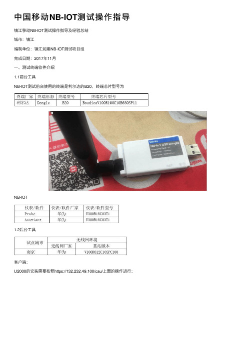
中国移动NB-IOT测试操作指导镇江移动NB-IOT测试操作指导及经验总结城市:镇江编制单位:镇江润建NB-IOT测试项⽬组完成⽇期:2017年11⽉⼀、测试终端软件介绍1.1前台⼯具NB-IOT测试前台使⽤的终端是利尔达的B20,终端芯⽚型号为NB-IOT1.2后台⼯具客户端;U2000的安装需要按照https://132.232.49.100/cau/上⾯的操作进⾏;对前台数据进⾏罐包,罐包采⽤的软件为如下图:(miperf可以直接复制到桌⾯使⽤)miperf.rar⼆、测试终端软件安装和使⽤2.1 软件安装打开GENEX Probe V3R18C03T1_LicenseEdition⽂件夹双击安装⽂件Setup.exe,按安装提⽰正常安装即可。
安装界⾯该程序需要在 Visual C++ 2008 环境下运⾏,因此需安装此编程环境。
Visual C++ 2008 程序安装界⾯2.2软件的合法使⽤GENEX Probe 3.18软件运⾏需要软件狗或硬件狗⽀持,本⽂介绍的是软件狗版本。
在安装软件后会弹出图 3 所⽰,将 ESN 记下来发给华为⼈员申请软件狗License。
点击 Update License 将申请到的 License ⽂件导⼊即可。
License 导⼊界⾯设备连接正常后,Ddisconnect图标为红⾊,右下⾓⼿机图标为绿⾊。
2.3测试终端和驱动安装测试终端正确安装驱动后,在电脑设备管理器的端⼝中将显⽰如下2个端⼝,如下图:注:测试终端驱动CodeLoaderInstaller[适配端⼝].rar CDM21216_Setup.rar2.4设备连接驱动安装后,测试终端插⼊电脑 USB ⼝会⾃动识别,同样,GPS驱动安装好后电脑设备管理器中也有相应的端⼝,⽤于测试软件中 GPS 连接的配置。
打开PROBE软件,然后点击 Configuration→Device Management→Device Configure 窗⼝的设备连接按钮或⼯具栏的设备连接按钮(样式与 Device Configure 窗⼝的设备连接按钮相同),以及左边⼯具栏Configure 下的按钮,点击该按钮会弹出设备连接窗⼝,如下图:设备连接点击最左边的添加设备按钮,添加测试设备型号 HUEWEI NB Boudica弹出的 Add Device 窗⼝,AT port选数值⼤的那个端⼝,COM port 选数值⼩的那个端⼝,COM Baud rate 是默认值,然后点击OK,如图:添加设备同样添加 GPS 时只要在 Type ⾥⾯选 GPS 选项,Model 选 NMEA 在弹出的窗⼝把你电脑端的 GPS 端⼝填到 COM port ⾥⾯即可。
MIPIRFFE协议使用不完全指南(附上代码详解和参考资料)第一部分
MIPIRFFE协议使⽤不完全指南(附上代码详解和参考资料)第⼀部分背景MIPI RFFE协议被控器件资料程序实现参考资料背景前段时间教研室需要制作⼀个拥有⾃动增益控制功能的放⼤器组,选来选去找到了⼀款英飞凌的放⼤器模块,该模块情况在第三部分详细介绍(具有代表性),重点在于这个模块使⽤MIPI RFFE协议控制,这个协议控制我之前没有使⽤过,但是我以前使⽤过类似SPI和IIC的协议感觉会差不多,但是实现的具体难度在于,不同于前述的SPI,IIC和CAN总线,这个总线的资料少的可怜,基本上只有官⽅提供的说明⽂档,我尝试从知⽹,IEEE等⽹站寻找资料发现也没有什么有实际指导意义的资料,但是通过尝试已经实现了通过协议控制器件的功能并在总线上挂载了4个设备,在硬件电路的设计和软件设计中遇到了很多问题也学到了很多东西,对于协议的⼤体已经明了,但是还有很多具体的功能没有实现和理解,在这⾥和⼤家分享和交流⼀下。
MIPI RFFE协议看这章之前请您先将MIPI RFFE协议下载下来。
(在我的页⾯有很多关于MIPI RFFE相关的资料)⽹上能找到的很多资料都是对于这个协议的描述,并没有触及到这个协议的实际的内容,这⼀章将⽐较详细的介绍MIPI RFFE协议的重点。
⽬录1. Introduction2. Terminology3. References4. Architecture and Operations Overview5. Physical Layer6. Protocol Layer7. Applications2.1 Definitions⾸先是协议⽤到的⼀些术语的解释:19 Address Frame是地址帧,⽤来标志需要写⼊的器件地址,该地址帧可以使主机区分挂载在总线上的器件从⽽分开控制,有⼀位的奇偶校验位(这个奇偶校验位在后⾯⼤量反复出现)。
20 Broadcast ⼴播不赘述21 ⼴播地址,和路由器当中的⼴播⼀样,⽽且地址为也⼀样,可以类⽐的理解。
Miperf操作指导(灌包)
Miperf操作指导1 操作系统要求该工具必须在XP、win 2003、win7系统下使用。
将该工具安装在服务器和终端连接电脑上。
2 工具说明使用该工具可实现UDP、TCP 的上行、下行灌包。
3 UDP灌包操作步骤1、Traffic mode:选择UDP2、Traffic direction:原则:谁灌谁上行。
终端下行:服务器侧选择UL,终端侧选择DL;终端上行:服务器侧选择DL,终端侧选择UL。
3、Host address:终端侧:填写服务器IP地址;服务器侧:填写终端业务IP地址。
4、Bandwidth:灌包带宽5、Execution time:灌包执行时间,根据需求设置6、MTU size:建议配置1000B7、Port:服务器侧和终端侧协商好一个没有使用的端口号,两边配置一致。
4 TCP灌包操作步骤和UDP灌包不同点不需要配置带宽和MTU size5 B593终端灌包操作由于B593 是LTE转wifi终端,笔记本电脑获取的地址是内网地址,从灌包服务器是无法找到内网地址,故在灌包操作上具有特殊性。
5.1 上行灌包内网访问灌包服务器地址不受影响,故按照一般操作流程即可。
5.2 下行灌包5.2.1服务器设置ip地址设置为B593获取大网地址,查询方法需要查看信令上核心网给该终端分配的ip地址。
1、将B593连接到probe上,并打开层三信令窗口2、右键点击hisi agent工具,选择power off后再点击power on(实际就是让终端重新入网,观察信令,默认终端是上电后自动开机,故看不到初始接入的信令)3、查询attachaccept中address-information中ip地址信息,将16进制转化为10进制。
例如:下图中0A 32 00 0E对应10.50.0.145.2.2B593侧设置连接B593web界面后修改DMZ设置下行UDP/TCP要到达PC网卡,需要首先在WebUI上NAT Settings > DMZ Settings页面配置DMZ。
最新(完美版)深圳LTE灌包操作及问题定位指导
深圳LTE灌包操作及问题定位指导一、背景知识1、灌包目前灌包采用的是miperf软件直接进行,支持TCP和UDP两种协议的灌包。
TCP是面向连接的可靠的有保证的一种传输机制,而UDP是与TCP相对应的一种协议,面向非连接的、无保证的传输机制。
图1图1是Iperf软件的设置界面,选择好TCP灌包还是UDP灌包,Traffic direction选择灌包的方向,相对UE来说下行灌包此时在服务器侧这里的设置就应该选择UL,如果UE 要上行灌包那么此时在服务器侧就应设置为DL,而在UE侧就设置为UL。
简单地说,就是谁灌包谁上行。
点击SHOW下面的Chart或者Messages可以在右方弹出灌包图表或者信息。
Host address填写对端的IP。
port可任意填写,只要端口没被占用即可,如果灌包时发现对端没收到包,可尝试更改端口号。
Report interval报告上报的时间间隔,通常为1s。
Execution time是灌包操作执行的时间,填个最大值即可。
Bandwidth目前采用下行100m,上行25m。
MTU size最大传输单元可以设置不同字节,视问题定位情况而定。
2、ping目前ping包是在基站侧通过网管MML命令ping核心网SGW,ping1000字节、1400字节、2000字节的包各ping100次,看是否丢包。
图2如图2所示,槽号填写主控板所在槽号,扩大规模网的站点都是6。
源IP地址填写基站的IP,目的IP地址填写SGW的IP。
可分别通过LST DEVIP和LST IPRT查询获得。
PING 报文长度分别为1000字节、1400字节、2000字节。
PING报文个数100次。
PING测试是为了辅助定位基站到核心网的传输问题,如果PING过程出现丢包,那传输应该是存在问题,否则,也不能想当然地说传输没有问题。
二、应用场景终端做FTP业务上下行速率异常时都可以采用灌包+ping包的方法,初步判断问题的方向:传输故障、FTP服务器能力问题还是空口环境问题。
手机RF MIPI应用指导
Defined by USID
Skyworks Solutions, Inc. Proprietary Information
7
Slave Register Space
RFFE has 16bit address register space, but mostly we only use 5bit address. Different address length register has different write/read command sequence.
Skyworks Solutions, Inc. Proprietary Information
2
RFFE Specification
Skyworks Solutions, Inc. Proprietary Information
3
Overview
MIPI – Mobile Industry Processor Interface RFFE – RF Front End Control Interface
Biggest Difference is the way in which the triggers are implemented!
Skyworks Solutions, Inc. Proprietary Information 20
Trigger Registers
This is an illustration of how triggers can work as defined by the MIPI RFFE specification. In this illustration all the triggers are enabled, IOW no trigger mask bits are set.
- 1、下载文档前请自行甄别文档内容的完整性,平台不提供额外的编辑、内容补充、找答案等附加服务。
- 2、"仅部分预览"的文档,不可在线预览部分如存在完整性等问题,可反馈申请退款(可完整预览的文档不适用该条件!)。
- 3、如文档侵犯您的权益,请联系客服反馈,我们会尽快为您处理(人工客服工作时间:9:00-18:30)。
Miperf操作指导1 操作系统要求
该工具必须在XP、win 2003、win7系统下使用。
将该工具安装在服务器和终端连接电脑上。
2 工具说明
使用该工具可实现UDP、TCP 的上行、下行灌包。
3 UDP灌包操作步骤
1、Traffic mode:选择UDP
2、Traffic direction:
原则:谁灌谁上行。
终端下行:服务器侧选择UL,终端侧选择DL;
终端上行:服务器侧选择DL,终端侧选择UL。
3、Host address:
终端侧:填写服务器IP地址;
服务器侧:填写终端业务IP地址。
4、Bandwidth:灌包带宽
5、Execution time:灌包执行时间,根据需求设置
6、MTU size:建议配置1000B
7、Port:服务器侧和终端侧协商好一个没有使用的端口号,两边配置一致。
4 TCP灌包操作步骤
和UDP灌包不同点不需要配置带宽和MTU size
5 B593终端灌包操作
由于B593 是LTE转wifi终端,笔记本电脑获取的地址是内网地址,从灌包服务器是无法找到内网地址,故在灌包操作上具有特殊性。
5.1 上行灌包
内网访问灌包服务器地址不受影响,故按照一般操作流程即可。
5.2 下行灌包
5.2.1服务器设置
ip地址设置为B593获取大网地址,查询方法需要查看信令上核心网给该终端分配的ip地址。
1、将B593连接到probe上,并打开层三信令窗口
2、右键点击hisi agent工具,选择power off后再点击power on(实际就是让终端重新入网,观察信令,默认终端是上电后自动开机,故看不到初始接入的信令)
3、查询attachaccept中address-information中ip地址信息,将16进制转化为10进制。
例如:下图中0A 32 00 0E对应10.50.0.14
5.2.2B593侧设置
连接B593web界面后修改DMZ设置
下行UDP/TCP要到达PC网卡,需要首先在WebUI上NAT Settings > DMZ Settings
页面配置DMZ。
查询获取,例如本地配置的192.168.1.2。
如果重新接入后,获取ip地址变化,DMZ中ip地址也需要同步更新。