毕设翻译 -纳米自组装-
毕设三项文档之-外文翻译
本科生毕业设计 (论文)
外文翻译
原文标题
Worlds Collide:
Exploring the Use of Social Media Technologies for
Online Learning
译文标题
世界的碰撞:
探索社交媒体技术在在线学习的应用
作者所在系别计算机科学与工程系作者所在专业计算机科学与技术作者所在班级
作者姓名
作者学号
指导教师姓名
指导教师职称讲师
完成时间2013年2月
北华航天工业学院教务处制
注:1. 指导教师对译文进行评阅时应注意以下几个方面:①翻译的外文文献与毕业设计(论文)的主题是否高度相关,并作为外文参考文献列入毕业设计(论文)的参考文献;②翻译的外文文献字数是否达到规定数量(3 000字以上);③译文语言是否准确、通顺、具有参考价值。
2. 外文原文应以附件的方式置于译文之后。
毕设翻译英文

轨道交通学院毕业设计(论文)外文翻译题目:列车车载的直流恒流源的设计专业电子信息工程班级10115111学号1011511137姓名赵士伟指导教师陈文2014 年3 月 3 日本文摘自:IEEE TRANSACTIONS ON INDUSTRY AND GENERAL APPLICATIONS VOL. IGA-2, NO.5 SEPT/OCT 1966Highly Regulated DC Power Supplies Abstract-The design and application of highly regulated dc power supplies present many subtle, diverse, and interesting problems. This paper discusses some of these problems (especially inconnection with medium power units) but emphasis has been placed more on circuit economics rather than on ultimate performance.Sophisticated methods and problems encountered in connection with precision reference supplies are therefore excluded. The problems discussed include the subjects of temperature coefficient,short-term drift, thermal drift, transient response degeneration caused by remote sensing, and switching preregualtor-type units and some of their performance characteristics.INTRODUCTIONANY SURVEY of the commercial de power supply field will uncover the fact that 0.01 percent regulated power supplies are standard types and can be obtained at relatively low costs. While most users of these power supplies do not require such high regulation, they never-theless get this at little extra cost for the simple reason that it costs the manufacturer very little to give him 0.01 percent instead of 0.1 percent. The performance of a power supply, however, includes other factors besides line and load regulation. This paper will discuss a few of these-namely, temperature coefficient, short-term drift, thermal drift, and transient response. Present medium power dc supplies commonly employ preregulation as a means of improving power/volume ratios and costs, but some characteristics of the power supply suffer by this approach. Some of the short-comings as well as advantages of this technology will be examined.TEMPERATURE COEFFICIENTA decade ago, most commercial power supplies were made to regulation specifications of 0.25 to 1 percent. The reference elements were gas diodes having temperature coefficients of the order of 0.01 percent [1]. Consequently, the TC (temperature coefficient) of the supply was small compared to the regulation specifications and often ignored. Today, the reference element often carries aTC specification greater than the regulation specification.While the latter may be improved considerably at little cost increase, this is not necessarily true of TC. Therefore,the use of very low TC zener diodes, matched differential amplifier stages, and low TC wire wound resistors must be analyzed carefully, if costs are to be kept low.A typical first amplifier stage is shown in Fig. 1. CRI is the reference zener diode and R, is the output adjustment potentiometer.Fig. 1. Input stage of power supply.Fig. 2. Equivalent circuit of zener reference.Let it be assumed that e3, the output of the stage, feedsadditional differential amplifiers, and under steady-state conditions e3 = 0. A variation of any of the parameters could cause the output to drift; while this is also true of the other stages, the effects are reduced by the gain of all previous stages. Consequently, the effects of other stages will be neglected. The following disculssion covers the effects of all elements having primary and secondary influences on the overall TC.Effect of R3The equivalent circuit of CRI -R3 branch is shown in Fig. 2. The zener ha's been replaced with its equivalent voltage source E/' and internal impedance R,. For high gain regulators, the input of the differential amplifier will have negligible change with variations of R3 so thatbefore and after a variation of R3 is made.If it is further assumed that IB << Iz; then from (1)Also,Eliminating I, from (2b),andNow, assuming thatthen,Equation (2b) can also be writtenThe Zener DiodeThe zener diode itself has a temperature coefficient andusually is the component that dominates the overall TCof the unit. For the circuit of Fig. 1, the TC ofthe circuit describes, in essence, the portion of the regulator TC contributed by the zener. If the bridge circuit shown in Fig. 1 were used in conjunction with a dropping resistor so that only a portion of the output voltage appeared across the bridge circuit shown, the TC of the unit and the zener would be different. Since the characteristic of zeners is so well known and so well described in the literature, a discussion will not be given here [2].Variation of Base-Emitter VoltagesNot only do the values of V,, of the differential am-plifier fail to match, but their differentials with tem perature also fail to match. This should not, however,suggest that matched pairs are required. The true reference voltage of Fig. 1 is not the value E,, but E, + (Vie, -Vbe2)-Since, for most practical applicatioinsthe TC of the reference will be the TC of the zener plusConsidering that it is difficult to obtain matched pairs that have differentials as poor as 50 V/°C, it becomes rather apparent that, in most cases, a matched pair bought specifically for TC may be overdesigning.Example 2: A standard available low-cost matched pair laims 30AV/°C. In conjunction with a 1N752, the ontribution to the overall TC would beTests, performed by the author on thirteen standard germanium signal transistors in the vicinity of room temperature and at a collector current level of 3 mA,indicated that it is reasonable to expect that 90 to 95 percent of the units would have a base-emitter voltage variation of -2.1 to -2.4 mV/°C. Spreads of this magnitude have also been verified by others (e.g., Steiger[3]). The worst matching of transistors led to less than 400 ,V/°C differential. In conjunction with a 1N752,even this would give a TC of better than 0.007%/0C.Variation of Base CurrentsThe base current of the transistors is given byA variation of this current causes a variation in signal voltage at the input to the differential amplifier due to finite source impedances. Matching source impedances is not particularly desirable, since it reduces the gain of the system and requires that transistors matched for I,o and A be used. Hunter [4 ] states that the TC of a is in the range of +0.2%/0C to -0.2%7/'C and that 1,, may be approximated bywhere Ao is the value at To.β is also temperature dependent and Steiger [3] experimentally determined the variation to be from about 0.5%/°C to 0.9%/0C.And,Fig. 3. Input circuit of Q2.The current AIB flows through the source impedance per Fig. 3. The drops in the resistance string, however, are subject to the constraint that EB (and AEB) are determined by the zener voltage and the base-emitter drops of Q1 and Q2. Consequently, if in going from temperature T1to T2 a change AEB occurs,The change in output voltage isAndExample 3: For Q2 (at 25°C)(see Example 1)∴Variation of R,The effects of a variation of the TC between RIA and RIB is sufficiently self-evident so that a discussion of the contribution is not included.SHORT-TERM DRIFTThe short-term drift of a supply is defined by the National Electrical Manufacturers Association (NEMA) as "a change in output over a period of time, which change is unrelated to input, environment, or load [5]."Much of the material described in the section on temperature coefficient is applicable here as well. It has been determined experimentally, however, that thermal air drafts in and near thevicinity ofthe powersupplycontributesenormouslyto theshort-termcharacteristics. Thecooling effects of moving air are quite well known, but it is not often recognized that even extremely slow air movements over such devices as zeners and transistors cause the junction temperature of these devices to change rapidly. If the TC of the supply is large compared to the regulation, then large variations in the output will be observed. Units having low TC's achieved by compensation-that is, by canceling out the effects of some omponents by equal and opposite effects of others may still be plagued by these drafts due to the difference in thermal time constants of the elements.Oftentimes, a matched transistor differential amplifier in a common envelope is used for the first amplifier just to equalize and eliminate the difference in cooling effects between the junctions. Approximations to this method include cementing or holding the transistors together, imbedding the transistors in a common metal block, etc. Excellent results were achieved by the author by placing the input stage and zener reference in a separate enclosure. This construction is shown in Fig. 4. The improvement in drift obtained by means of the addition of the metal cover is demonstrated dramatically in Fig. 5.Fig. 5. Short-term drift of a power supply similar to the one shown in Fig. 4 with and without protective covers. The unit was operated without the cover until time tl, when the cover was attached. The initial voltage change following t, is due to a temperaturerise inside the box.Fig. 5. Short-term drift of a power supply similar to the one shown n Fig. 4 withand without protective covers. The unit was operated without the cover until time tl, when the cover was attached. The initial voltage change following t, is due to atemperature rise inside the box.If potentiometers are used in the supply for output adjustment (e.g., RI), care should be used in choosing the value and design. Variations of the contact resistance can cause drift. It is not always necessary, however, to resort to the expense of high-resolution multiturn precision units to obtain low drift. A reduction in range of adjustment, use of low-resistance alloys and low-resolution units which permit the contact arm to rest firmly between turns, may be just as satisfactory. Of course, other considerations should include the ability of both the arms and the wire to resist corrosion. Silicone greases are helpful here. Periodic movement of contact arms has been found helpful in "healing" corroded elements.THERMAL DRIFTNEMA defines thermal drift as "a change in output over a period of time, due to changes in internal ambient temperatures not normally related to environmental changes. Thermal drift is usually associated with changes in line voltage and/or load changes [5]."Thermal drift, therefore, is strongly related to the TC of the supply as well as its overall thermal design. By proper placement of critical components it is possible to greatly reduce or even eliminate the effect entirely. It is not uncommon for supplies of the 0.01 percent(regulation) variety to have drifts of between 0.05 to 0.15 percent for full line or full load variations. In fact, one manufacturer has suggested that anything better than 0.15 percent is good. Solutions to reducing thermal drift other than the obvious approach of improving the TC and reducing internal losses include a mechanical design that sets up a physical and thermal barrier between the critical amplifier components and heat dissipating elements. Exposure to outside surfaces with good ventilation is recommended. With care, 0.01 to 0.05 percent is obtainable.TRANSIENT RESPONSEMost power supplies of the type being discussed have a capacitor across the load terminals. This is used for stabilization purposes and usually determines the dominant time constant of the supply. The presence of this capacitor unfortunately leads to undesirable transient phenomena when the supply is used in the remote sensing mode①. Normally, transistorized power supplies respond in microseconds, but as the author has pointed out [6], the response can degenerate severely in remote sensing .The equivalent circuit is shown in Fig. 6. The leads from the power supply to the load introduce resistance r. Is is the sensing current of the supply and is relatively constant.Under equilibrium conditions,A sudden load change will produce the transient of Fig. 7. The initial "spike" is caused by an inductive surge Ldi/dt; the longer linear discharge following is the resultof the capacitor trying to discharge (or charge). The discharge time iswhereandThe limitations of I,, are usually not due to available drive of the final amplifier stages but to other limitations, current limiting being the most common. Units using pre regulators of the switching type (transistor or SCR types) should be looked at carefully if the characteristics mentioned represent a problem.①Remote sensing is the process by which the power supply senses voltage directly at the load.Fig. 6. Output equivalent circuit at remote sensing.Fig. 7. Transient response, remote sensing.Fig. 8. Block diagram.Preregulated supplies are used to reduce size and losses by monitoring and controlling the voltage across the class-A-type series passing stage (Fig. 8). Since the main regulator invariably responds much quicker than the preregulator, sufficient reserve should always be built into the drop across the passing stage. Failure to provide this may result in saturation of the passing stage when load is applied, resulting in a response time which is that of the preregulator itself.SWITCHING PREREGULATOR-TYPE UNITS The conventional class-A-type transistorized power supply becomes rather bulky, expensive, and crowded with passing stages, as the current and power level of the supply increases. The requirement of wide output adjustment range, coupled with the ability of the supply to be remotely programmable, aggravates the condition enormously. For these reasons the high-efficiency switching regulator has been employed as a preregulator in commercial as well as military supplies for many years. The overwhelming majority of the supplies used silicon controlled rectifiers as the control element. For systems operating from 60-cycle sources, this preregulator responds in 20 to 50 ms.Recent improvements in high-voltage, high-power switching transistors has made the switching transistor pproach more attractive. This system offers a somewhat lower-cost, lower-volume approach coupled with a submillisecond response time. This is brought about by a high switching rate that is normally independent of line frequency. The switching frequency may be fixed, a controlled variable or an independent self-generated (by the LC filter circuit) parameter [7], [8]. Faster response time is highly desirable since it reduces the amount of reserve voltage required across the passing stage or the amount of (storage) capacity required in the preregulator filter.A transistor suitable for operating as a power switch has a high-current, high-voltage rating coupled with low leakage current. Unfortunately, these characteristics are achieved by a sacrifice in thermal capacity, so that simultaneous conditions of voltage and current leading to high peak power could be disastrous. It therefore becomes mandatory to design for sufficient switch drive during peak load conditions and also incorporate current-limiting or rapid overload protection systems.Commercial wide-range power supplies invariably have output current limiting, but this does not limit the preregulator currents except during steady-state load conditions (including short circuits). Consider, for example, a power supply operating at short circuit and the short being removed suddenly. Referring to Fig. 8, the output would rise rapidly, reduce the passing stage voltage, and close the switching transistor. The resulting transient extends over many cycles (switching rate) so that the inductance of the preregulator filter becomes totally inadequate to limit current flow. Therefore, the current will rise until steady state is resumed, circuit resistance causes limiting, or insufficient drive causes the switch to come out of saturation. The latter condition leads to switch failure.Other operating conditions that would produce similar transients include output voltage programming and initial turn-on of the supply. Momentary interruption of input power should also be a prime consideration.One solution to the problem is to limit the rate of change of voltage that can appear across the passing stage to a value that the preregulator can follow. This can be done conveniently by the addition of sufficient output capacitance. This capacitance inconjunction with the current limiting characteristic would produce a maximum rate of change ofwhereC0 = output capacity.Assuming that the preregulator follows this change and has a filter capacitor Cl, then the switch current isDuring power on, the preregulator reference voltage rise must also be limited. Taking this into account,whereER = passing stage voltageTl = time constant of reference supply.The use of SCR's to replace the transistors would be a marked improvement due to higher surge current ratings, but turning them off requires large energy sources. While the gate turn-off SCR seems to offer a good compromise to the overall problem, the severe limitations in current ratings presently restrict their use.REFERENCES[1] J. G. Truxal, Control Engineer's Handbook. New York: McGrawHill, 1958, pp. 11-19.[2] Motorola Zener Diode/Rectifier Handbook, 2nd ed. 1961.[3] W. Steiger, "A transistor temperature analysis and its applica-tion to differential amplifiers," IRE Trans. on Instrumentation,vol. 1-8, pp. 82-91, December 1959.[4] L. P. Hunter, Handbook of Semi-Conductor Electronics. NewYork: McGraw Hill, 1956, p. 13-3.[5] "Standards publication for regulated electronic dc powersupplies," (unpublished draft) Electronic Power Supply Group,Semi-Conductor Power Converter Section, NEMA.[6] P. Muchnick, "Remote sensing of transistorized power sup-plies," Electronic Products, September 1962.[7] R. D. Loucks, "Considerations in the design of switching typeregulators," Solid State Design, April 1963.[8] D. Hancock and B. Kurger, "High efficiency regulated powersupply utilizing high speed switching," presented at the AIEEWinter General Meeting, New York, N. Y., January 27-February 1, 1963.[9] R. D. Middlebrook, Differential Amplifiers. New York: Wiley,1963.[10] Sorensen Controlled Power Catalog and Handbook. Sorensen,Unit of Raytheon Company, South Norwalk, Conn.With the rapid development of electronic technology, application field of electronic system is more and more extensive, electronic equipment, there are more and more people work with electronic equipment, life is increasingly close relationship. Any electronic equipment are inseparable from reliable power supply for power requirements, they more and more is also high. Electronic equipment miniaturized and low cost in the power of light and thin, small and efficient for development direction. The traditional transistors series adjustment manostat is continuous control linear manostat. This traditional manostat technology more mature, and there has been a large number of integrated linear manostat module, has the stable performance is good, output ripple voltage small, reliable operation, etc. But usually need are bulky and heavy industrial frequency transformer and bulk and weight are big filter.In the 1950s, NASA to miniaturization, light weight as the goal, for a rocket carrying the switch power development. In almost half a century of development process, switch power because of its small volume, light weight, high efficiency, wide range, voltage advantages in electric, control, computer, and many other areas of electronic equipment has been widely used. In the 1980s, a computer is made up of all of switch power supply, the first complete computer power generation. Throughout the 1990s, switching power supply in electronics, electrical equipment, home appliances areas to be widely, switch power technology into the rapid development. In addition, large scale integrated circuit technology, and the rapid development of switch power supply with a qualitative leap, raised high frequency power products of, miniaturization, modular tide.Power switch tube, PWM controller and high-frequency transformer is an indispensable part of the switch power supply. The traditional switch power supply is normally made by using high frequency power switch tube division and the pins, such as using PWM integrated controller UC3842 + MOSFET is domestic small power switch power supply, the design method of a more popularity.Since the 1970s, emerged in many function complete integrated control circuit, switch power supply circuit increasingly simplified, working frequency enhances unceasingly, improving efficiency, and for power miniaturization provides the broad prospect. Three end off-line pulse width modulation monolithic integrated circuit TOP (Three switch Line) will Terminal Off with power switch MOSFET PWM controller one package together, has become the mainstream of switch power IC development. Adopt TOP switch IC design switch power, can make the circuit simplified, volume further narrowing, cost also is decreased obviouslyMonolithic switching power supply has the monolithic integrated, the minimalist peripheral circuit, best performance index, no work frequency transformer can constitute a significant advantage switching power supply, etc. American PI (with) company in Power in the mid 1990s first launched the new high frequency switching Power supply chip, known as the "top switch Power", with low cost, simple circuit, higher efficiency. The first generation of products launched in 1994 represented TOP100/200 series, the second generation product is the TOPSwitch - debuted in 1997 Ⅱ. The above products once appeared showed strong vitality and he greatly simplifies thedesign of 150W following switching power supply and the development of new products for the new job, also, high efficiency and low cost switch power supply promotion and popularization created good condition, which can be widely used in instrumentation, notebook computers, mobile phones, TV, VCD and DVD, perturbation VCR, mobile phone battery chargers, power amplifier and other fields, and form various miniaturization, density, on price can compete with the linear manostat AC/DC power transformation module.Switching power supply to integrated direction of future development will be the main trend, power density will more and more big, to process requirements will increasingly high. In semiconductor devices and magnetic materials, no new breakthrough technology progress before major might find it hard to achieve, technology innovation will focus on how to improve the efficiency and focus on reducing weight. Therefore, craft level will be in the position of power supply manufacturing higher in. In addition, the application of digital control IC is the future direction of the development of a switch power. This trust in DSP for speed and anti-interference technology unceasing enhancement. As for advanced control method, now the individual feels haven't seen practicability of the method appears particularly strong,perhaps with the popularity of digital control, and there are some new control theory into switching power supply.(1)The technology: with high frequency switching frequencies increase, switch converter volume also decrease, power density has also been boosted, dynamic response improved. Small power DC - DC converter switch frequency will rise to MHz. But as the switch frequency unceasing enhancement, switch components and passive components loss increases, high-frequency parasitic parameters and high-frequency EMI and so on the new issues will also be caused.(2)Soft switching technologies: in order to improve the efficiency ofnon-linearity of various soft switch, commutation technical application and hygiene, representative of soft switch technology is passive and active soft switch technology, mainly including zero voltage switch/zero current switch (ZVS/ZCS) resonance, quasi resonant, zero voltage/zero current pulse width modulation technology (ZVS/ZCS - PWM) and zero voltage transition/zero current transition pulse width modulation (PWM) ZVT/ZCT - technical, etc. By means of soft switch technology can effectively reduce switch loss and switch stress, help converter transformation efficiency (3)Power factor correction technology (IC simplifies PFC). At present mainly divided into IC simplifies PFC technology passive and active IC simplifies PFC technology using IC simplifies PFC technology two kinds big, IC simplifies PFC technology can improve AC - DC change device input power factor, reduce the harmonic pollution of power grid.(4)Modular technology. Modular technology can meet the needs of the distributed power system, enhance the system reliability.(5)Low output voltage technology. With the continuous development of semiconductor manufacturing technology, microprocessor and portable electronic devices work more and more low, this requires future DC - DC converter can provide low output voltage to adapt microprocessor and power supply requirement of portable electronic devicesPeople in switching power supply technical fields are edge developing related power electronics device, the side of frequency conversion technology, development of switch between mutual promotion push switch power supply with more than two year growth toward light, digital small, thin, low noise and high reliability, anti-interference direction. Switching powersupply can be divided into the AC/DC and DC/DC two kinds big, also have AC/AC DC/AC as inverter DC/DC converter is now realize modular, and design technology and production process at home and abroad, are mature and standardization, and has approved by users, but the AC/DC modular, because of its own characteristics in the process of making modular, meet more complex technology and craft manufacture problems. The following two types of switch power supply respectively on the structure and properties of this.Switching power supply is the development direction of high frequency, high reliability, low consumption, low noise, anti-jamming and modular. Because light switch power, small, thin key techniques are changed, so high overseas each big switch power supply manufacturer are devoted to the development of new high intelligent synchronous rectifier, especially the improvement of secondary devices of the device, and power loss of Zn ferrite (Mn) material? By increasing scientific and technological innovation, to enhance in high frequency and larger magnetic flux density (Bs) can get high magnetic under the miniaturization of, and capacitor is a key technology. SMT technology application makes switching power supply has made considerable progress, both sides in the circuitboard to ensure that decorate components of switch power supply light, small, thin. The high frequency switching power supply of the traditional PWM must innovate switch technology, to realize the ZCS ZVS, soft switch technology has becomethe mainstream of switch power supply technical, and greatly improve the efficiency of switch power. For high reliability index, America's switch power producers, reduce by lowering operating current measures such as junction temperature of the device, in order to reduce stress the reliability of products made greatly increased.Modularity is of the general development of switch power supply trend can be modular power component distributed power system, can be designed to N + 1 redundant system, and realize the capacity expansion parallel. According to switch power running large noise this one defect, if separate the pursuit of high frequency noise will increase its with the partial resonance, and transform circuit technology, high frequency can be realized in theory and can reduce the noise, but part of the practical application of resonant conversion technology still have a technical problem, so in this area still need to carry out a lot of work, in order to make the technology to practional utilization.Power electronic technology unceasing innovation, switch power supply industry has broad prospects for development. To speed up the development of switch power industry in China, we must walk speed of technological innovation road, combination with Chinese characteristics in the joint development path, for I the high-speed development of national economy to make the contribution. The basic principle and component functionAccording to the control principle of switch power to classification, we have the following 3 kinds of work mode:1) pulse width adjustment type, abbreviation Modulation PulseWidth pulse width Modulation (PWM) type, abbreviation for. Its main characteristic is fixed switching frequency, pulse width to adjust by changing voltage 390v, realize the purpose. Its core is the pulse width modulator. Switch cycle for designing filter circuit fixed provided convenience. However, its shortcomings is influenced by the power switch conduction time limit minimum of output voltage cannot be wide range regulation; In addition, the output will take dummy loads commonly (also called pre load), in order to prevent the drag elevated when output voltage. At present, most of the integrated switch power adopt PWM way.2) pulse frequency Modulation mode pulse frequency Modulation (, referred to PulseFrequency Modulation, abbreviation for PFM) type. Its characteristic is will pulse width fixed by changing switch frequency to adjust voltage 390v, realize the purpose. Its core is the pulse frequency modulator. Circuit design to use fixed pulse-width generator to replace the pulse width omdulatros and use sawtooth wave generator voltage? Frequency converter (for example VCO changes frequency VCO). It on voltage stability principle is: when the output voltage Uo rises, the output signal controller pulse width unchanged and cycle longer, make Uo 390v decreases, and reduction. PFM type of switch power supply output voltage range is very wide, output terminal don't meet dummy loads. PWM way and way of PFM respectively modulating waveform is shown in figure 1 (a), (b) shows, tp says pulse width (namely power switch tube conduction time tON), T represent cycle. It can be easy to see the difference between the two. But they have something in common: (1) all use time ratio control (TRC) on voltage stability principle, whether change tp, finally adjustment or T is。
汽车电子毕设设计外文文献翻译(适用于毕业论文外文翻译+中英文对照)

Ultrasonic ranging system designPublication title: Sensor Review. Bradford: 1993.Vol.ABSTRACT: Ultrasonic ranging technology has wide using worth in many fields, such as the industrial locale, vehicle navigation and sonar engineering. Now it has been used in level measurement, self-guided autonomous vehicles, fieldwork robots automotive navigation, air and underwater target detection, identification, location and so on. So there is an important practicing meaning to learn the ranging theory and ways deeply. To improve the precision of the ultrasonic ranging system in hand, satisfy the request of the engineering personnel for the ranging precision, the bound and the usage, a portable ultrasonic ranging system based on the single chip processor was developed.Keywords: Ultrasound, Ranging System, Single Chip Processor1. IntroductiveWith the development of science and technology, the improvement of people’s standard of living, speeding up the development and construction of the city. Urban drainage system have greatly developed their situation is construction improving. However, due to historical reasons many unpredictable factors in the synthesis of her time, the city drainage system. In particular drainage system often lags behind urban construction. Therefore, there are often good building excavation has been building facilities to upgrade the drainage system phenomenon. It brought to the city sewage, and it is clear to the city sewage and drainage culvert in the sewage treatment system.Co mfort is very important to people’s lives. Mobile robots designed to clear the drainage culvert and the automatic control system Free sewage culvert clear guarantee robots, the robot is designed to clear the culvert sewage to the core. Control system is the core component of the development of ultrasonic range finder. Therefore, it is very important to design a good ultrasonic range finder.2. A principle of ultrasonic distance measurementThe application of AT89C51:SCM is a major piece of computer components are integrated into the chip micro-computer. It is a multi-interface and counting on the micro-controller integration, and intelligence products are widely used in industrial automation. and MCS-51 microcontroller is a typical and representative.Microcontrollers are used in a multitude of commercial applications such as modems, motor-control systems, air conditioner control systems, automotive engine and among others. The high processing speed and enhanced peripheral set of these microcontrollers make them suitable for such high-speed event-based applications. However, these critical application domains also require that these microcontrollers are highly reliable. The high reliability and low market risks can be ensured by a robust testing process and a proper tools environment for the validation of these microcontrollers both at the component and at the system level. Intel Plaform Engineering department developed an object-oriented multi-threaded test environment for the validation of its AT89C51 automotive microcontrollers. The goals of this environment was not only to provide a robust testing environment for the AT89C51 automotive microcontrollers, but to develop an environment which can be easily extended and reused for the validation of several other future microcontrollers. The environment was developed in conjunction with Microsoft Foundation Classes(AT89C51).1.1 Features* Compatible with MCS-51 Products* 2Kbytes of Reprogrammable Flash MemoryEndurance: 1,000Write/Erase Cycles* 2.7V to 6V Operating Range* Fully Static operation: 0Hz to 24MHz* Two-level program memory lock* 128x8-bit internal RAM* 15programmable I/O lines* Two 16-bit timer/counters* Six interrupt sources*Programmable serial UART channel* Direct LED drive output* On-chip analog comparator* Low power idle and power down modes1.2 DescriptionThe AT89C2051 is a low-voltage, high-performance CMOS 8-bit microcomputer with 2Kbytes of flash programmable and erasable read only memory (PEROM). The device is manufactured using Atmel’s high density nonvolatile memory technology and is compatible with the industry standard MCS-51 instruction set and pinout. By combining a versatile 8-bit CPU with flash on a monolithic chip, the Atmel AT89C2051 is a powerful microcomputer which provides a highly flexible and cost effective solution to many embedded control applications.The AT89C2051 provides the following standard features: 2Kbytes of flash,128bytes of RAM, 15 I/O lines, two 16-bit timer/counters, a five vector two-level interrupt architecture, a full duplex serial port, a precision analog comparator, on-chip oscillator and clock circuitry. In addition, the AT89C2051 is designed with static logicfor operation down to zero frequency and supports two software selectable power saving modes. The idle mode stops the CPU while allowing the RAM, timer/counters, serial port and interrupt system to continue functioning. The power down mode saves the RAM contents but freezer the oscillator disabling all other chip functions until the next hardware reset.1.3 Pin Configuration1.4 Pin DescriptionVCC Supply voltage.GND Ground.Prot 1Prot 1 is an 8-bit bidirectional I/O port. Port pins P1.2 to P1.7 provide internal pullups. P1.0 and P1.1 require external pullups. P1.0 and P1.1 also serve as the positive input (AIN0) and the negative input (AIN1), respectively, of the on-chip precision analog comparator. The port 1 output buffers can sink 20mA and can drive LED displays directly. When 1s are written to port 1 pins, they can be used as inputs. When pins P1.2 to P1.7 are used as input and are externally pulled low, they will source current (IIL) because of the internal pullups.Port 3Port 3 pins P3.0 to P3.5, P3.7 are seven bidirectional I/O pins with internal pullups. P3.6 is hard-wired as an input to the output of the on-chip comparator and is not accessible as a general purpose I/O pin. The port 3 output buffers can sink 20mA. When 1s are written to port 3 pins they are pulled high by the internal pullups and can be used as inputs. As inputs, port 3 pins that are externally being pulled low will source current (IIL) because of the pullups.Port 3 also serves the functions of various special features of the AT89C2051 as listed below.1.5 Programming the FlashThe AT89C2051 is shipped with the 2 Kbytes of on-chip PEROM code memory array in the erased state (i.e., contents=FFH) and ready to be programmed. The code memory array is programmed one byte at a time. Once the array is programmed, to re-program any non-blank byte, the entire memory array needs to be erased electrically.Internal address counter: the AT89C2051 contains an internal PEROM address counter which is always reset to 000H on the rising edge of RST and is advanced applying a positive going pulse to pin XTAL1.Programming algorithm: to program the AT89C2051, the following sequence is recommended.1. power-up sequence:Apply power between VCC and GND pins Set RST and XTAL1 to GNDWith all other pins floating , wait for greater than 10 milliseconds2. Set pin RST to ‘H’ set pin P3.2 to ‘H’3. Apply the appropriate combination of ‘H’ or ‘L’ logic to pins P3.3, P3.4, P3.5,P3.7 to select one of the programming operations shown in the PEROM programming modes table.To program and Verify the Array:4. Apply data for code byte at location 000H to P1.0 to P1.7.5.Raise RST to 12V to enable programming.5. Pulse P3.2 once to program a byte in the PEROM array or the lock bits. The byte-write cycle is self-timed and typically takes 1.2ms.6. To verify the programmed data, lower RST from 12V to logic ‘H’ level and set pins P3.3 to P3.7 to the appropriate levels. Output data can be read at the port P1 pins.7. To program a byte at the next address location, pulse XTAL1 pin once to advance the internal address counter. Apply new data to the port P1 pins.8. Repeat steps 5 through 8, changing data and advancing the address counter for the entire 2 Kbytes array or until the end of the object file is reached.9. Power-off sequence: set XTAL1 to ‘L’ set RST to ‘L’Float all other I/O pins Turn VCC power off2.1 The principle of piezoelectric ultrasonic generatorPiezoelectric ultrasonic generator is the use of piezoelectric crystal resonators to work. Ultrasonic generator, the internal structure as shown, it has two piezoelectric chip and a resonance plate. When it’s two plus pulse signal, the frequency equal to the intrinsic piezoelectric oscillation frequency chip, the chip will happen piezoelectric resonance, and promote the development of plate vibration resonance, ultrasound is generated. Conversely, it will be for vibration suppression of piezoelectric chip, the mechanical energy is converted to electrical signals, then it becomes the ultrasonic receiver.The traditional way to determine the moment of the echo’s arrival is based on thresholding the received signal with a fixed reference. The threshold is chosen well above the noise level, whereas the moment of arrival of an echo is defined as the first moment the echo signal surpasses that threshold. The intensity of an echo reflecting from an object strongly depends on the object’s nature, size and distance from the sensor. Further, the time interval from the echo’s starting point to the moment when it surpasses the threshold changes with the intensity of the echo. As a consequence, a considerable error may occur even two echoes with different intensities arriving exactly at the same time will surpass the threshold at different moments. The stronger one will surpass the threshold earlier than the weaker, so it will be considered as belonging to a nearer object.2.2 The principle of ultrasonic distance measurementUltrasonic transmitter in a direction to launch ultrasound, in the moment to launch the beginning of time at the same time, the spread of ultrasound in the air, obstacles on his way to return immediately, the ultrasonic reflected wave received by the receiverimmediately stop the clock. Ultrasound in the air as the propagation velocity of 340m/s, according to the timer records the time t, we can calculate the distance between the launch distance barrier(s), that is: s=340t / 23. Ultrasonic Ranging System for the Second Circuit DesignSystem is characterized by single-chip microcomputer to control the use of ultrasonic transmitter and ultrasonic receiver since the launch from time to time, single-chip selection of 875, economic-to-use, and the chip has 4K of ROM, to facilitate programming.3.1 40 kHz ultrasonic pulse generated with the launchRanging system using the ultrasonic sensor of piezoelectric ceramic sensorsUCM40, its operating voltage of the pulse signal is 40kHz, which by the single-chip implementation of the following procedures to generate.puzel: mov 14h, # 12h; ultrasonic firing continued 200msHere: cpl p1.0; output 40kHz square wavenop;nop;nop;djnz 14h, here;retRanging in front of single-chip termination circuit P1.0 input port, single chip implementation of the above procedure, the P1.0 port in a 40kHz pulse output signal, after amplification transistor T, the drive to launch the first ultrasonic UCM40T, issued 40kHz ultrasonic pulse, and the continued launch of 200ms. Ranging the right and the left side of the circuit, respectively, then input port P1.1 and P1.2, the working principle and circuit in front of the same location.3.2 Reception and processing of ultrasonicUsed to receive the first launch of the first pair UCM40R, the ultrasonic pulse modulation signal into an alternating voltage, the op-amp amplification IC1A and after polarization IC1B to IC2. IC2 is locked loop with audio decoder chip LM567, internal voltage-controlled oscillator center frequency of f0=1/1.1R8C3, capacitor C4 determinetheir target bandwidth. R8-conditioning in the launch of the high jump 8 feet into a low-level, as interrupt request signals to the single-chip processing.Ranging in front of single-chip termination circuit output port INT0 interrupt the highest priority, right or left location of the output circuit with output gate IC3A access INT1 port single-chip, while single-chip P1.3 and P1.4 received input IC3A, interrupted by the process to identify the source of inquiry to deal with, interrupt priority level for the first left right after. Part of the source code is as follows:Receivel: push pswpush accclr ex1; related external interrupt 1jnb p1.1, right; P1.1 pin to 0, ranging from right to interrupt service routine circuitjnb p1.2, left; P1.2 pin to 0, to the left ranging circuit interrupt service routinereturn: SETB EX1; open external interrupt 1pop accpop pswretiright: …; right location entrance circuit interrupt service routineAjmp Returnleft: …; left ranging entrance circuit interrupt service routineAjmp Return3.3 The calculation of ultrasonic propagation timeWhen you start firing at the same time start the single-chip circuitry within the timer T0, the use of timer counting function records the time and the launch of ultrasonic reflected wave received time. When you receive the ultrasonic reflected wave, the receiver circuit output a negative jump in the end of INT0 or INT1 interrupt request generates a signal, single-chip microcomputer in response to external interrupt request, the implementation of the external interrupt service subroutine, read the time difference, calculating the distance. Some of its source code is as follows:RECEIVE0: PUSH PSWPUSH ACCCLR EX0; related external interrupt 0MOV R7, TH0; read the time valueMOV R6, TL0CLR CMOV A, R6SUBB A, #0BBH; calculate the time differenceMOV 31H, A; storage resultsMOV A, R7SUBB A, # 3CHMOV 30H, ASETB EX0; open external interrupt 0\POP ACCPOP PSWRETIFor a flat target, a distance measurement consists of two phases: a coarse measurement and a fine measurement:Step 1: Transmission of one pulse train to produce a simple ultrasonic wave.Step 2: Changing the gain of both echo amplifiers according to equation, until the echo is detected.Step 3: Detection of the amplitudes and zero-crossing times of both echoes.Step 4: Setting the gains of both echo amplifiers to normalize the output at, say 3 volts. Setting the period of the next pulses according to the: period of echoes. Setting the time window according to the data of step 2.Step 5: Sending two pulse trains to produce an interfered wave. Testing the zero-crossing times and amplitudes of the echoes. If phase inversion occurs in the echo, determine to otherwise calculate to by interpolation using the amplitudes near the trough. Derive t sub m1 and t sub m2.Step 6: Calculation of the distance y using equation.4、The ultrasonic ranging system software designSoftware is divided into two parts, the main program and interrupt service routine. Completion of the work of the main program is initialized, each sequence of ultrasonic transmitting and receiving control.Interrupt service routines from time to time to complete three of the rotation direction of ultrasonic launch, the main external interrupt service subroutine to read the value of completion time, distance calculation, the results of the output and so on.5、ConclusionsRequired measuring range of 30cm-200cm objects inside the plane to do a number of measurements found that the maximum error is 0.5cm, and good reproducibility. Single-chip design can be seen on the ultrasonic ranging system has a hardware structure is simple, reliable, small features such as measurement error. Therefore, it can be used not only for mobile robot can be used in other detection system.Thoughts: As for why the receiver do not have the transistor amplifier circuit, because the magnification well, integrated amplifier, but also with automatic gain control level, magnification to 76dB, the center frequency is 38k to 40k, is exactly resonant ultrasonic sensors frequency.6、Parking sensor6.1 Parking sensor introductionReversing radar, full name is "reversing the anti-collision radar, also known as" parking assist device, car parking or reversing the safety of assistive devices, ultrasonic sensors(commonly known as probes), controls and displays (or buzzer)and other components. To inform the driver around the obstacle to the sound or a moreintuitive display to lift the driver parking, reversing and start the vehicle around tovisit the distress caused by, and to help the driver to remove the vision deadends and blurred vision defects and improve driving safety.6.2 Reversing radar detection principleReversing radar, according to high-speed flight of the bats in thenight, not collided with any obstacle principles of design anddevelopment. Probe mounted on the rear bumper, according to different price and brand, the probe only ranging from two, three, four, six, eight,respectively, pipe around. The probe radiation, 45-degree angle up and downabout the search target. The greatest advantage is to explore lower than the bumper of the driver from the rear window is difficult to see obstacles, and the police, suchas flower beds, children playing in the squatting on the car.Display parking sensor installed in the rear view mirror, it constantlyremind drivers to car distance behindthe object distance to the dangerous distance, the buzzer starts singing, allow the driver to stop. When the gear lever linked into reverse gear, reversing radar, auto-start the work, the working range of 0.3 to 2.0 meters, so stop when the driver was very practical. Reversing radar is equivalent to an ultrasound probe for ultrasonic probe can be divided into two categories: First, Electrical, ultrasonic, the second is to use mechanical means to produce ultrasound, in view of the more commonly used piezoelectric ultrasonic generator, it has two power chips and a soundingboard, plus apulse signal when the poles, its frequency equal to the intrinsic oscillation frequency of the piezoelectric pressure chip will be resonant and drivenby the vibration of the sounding board, the mechanical energy into electrical signal, which became the ultrasonic probe works. In order to better study Ultrasonic and use up, people have to design and manufacture of ultrasonic sound, the ultrasonic probe tobe used in the use of car parking sensor. With this principle in a non-contactdetection technology for distance measurement is simple, convenient and rapid, easyto do real-time control, distance accuracy of practical industrial requirements. Parking sensor for ranging send out ultrasonic signal at a givenmoment, and shot in the face of the measured object back to the signal wave, reversing radar receiver to use statistics in the ultrasonic signal from the transmitter to receive echo signals calculate the propagation velocity in the medium, which can calculate the distance of the probe and to detect objects.6.3 Reversing radar functionality and performanceParking sensor can be divided into the LCD distance display, audible alarm, and azimuth directions, voice prompts, automatic probe detection function is complete, reversing radar distance, audible alarm, position-indicating function. A good performance reversing radar, its main properties include: (1) sensitivity, whether theresponse fast enough when there is an obstacle. (2) the existence of blind spots. (3) detection distance range.6.4 Each part of the roleReversing radar has the following effects: (1) ultrasonic sensor: used tolaunch and receive ultrasonic signals, ultrasonic sensors canmeasure distance. (2) host: after the launch of the sine wave pulse to the ultrasonic sensors, and process the received signal, to calculate the distance value, the data and monitor communication. (3) display or abuzzer: the receivinghost from the data, and display the distance value and provide differentlevels according to the distance from the alarm sound.6.5 Cautions1, the installation height: general ground: car before the installation of 45 ~55: 50 ~ 65cmcar after installation. 2, regular cleaningof the probe to prevent the fill. 3, do not use the hardstuff the probe surface cover will produce false positives or ranging allowed toprobe surface coverage, such as mud. 4, winter to avoid freezing. 5, 6 / 8 probe reversing radar before and after the probe is not free to swap may cause the ChangMing false positive problem. 6, note that the probe mounting orientation, in accordance with UP installation upward. 7, the probe is not recommended to install sheetmetal, sheet metal vibration will cause the probe resonance, resulting in false positives.超声测距系统设计原文出处:传感器文摘布拉福德:1993年超声测距技术在工业现场、车辆导航、水声工程等领域具有广泛的应用价值,目前已应用于物位测量、机器人自动导航以及空气中与水下的目标探测、识别、定位等场合。
毕设英文翻译
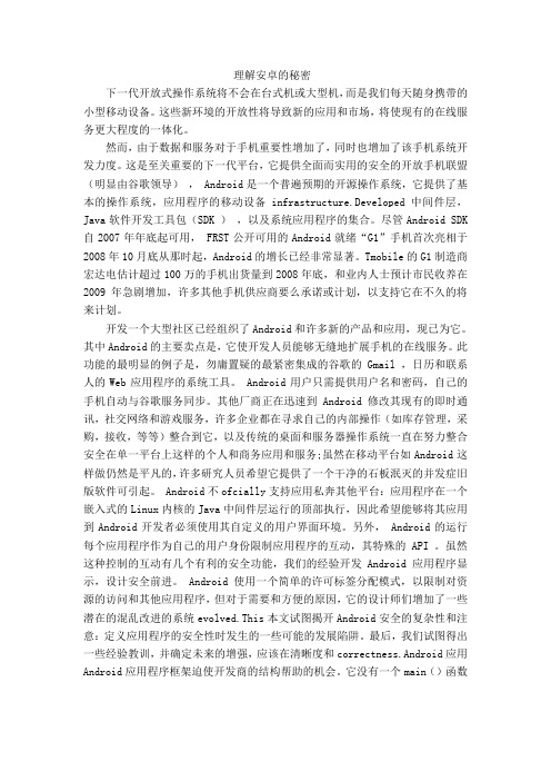
理解安卓的秘密下一代开放式操作系统将不会在台式机或大型机,而是我们每天随身携带的小型移动设备。
这些新环境的开放性将导致新的应用和市场,将使现有的在线服务更大程度的一体化。
然而,由于数据和服务对于手机重要性增加了,同时也增加了该手机系统开发力度。
这是至关重要的下一代平台,它提供全面而实用的安全的开放手机联盟(明显由谷歌领导), Android是一个普遍预期的开源操作系统,它提供了基本的操作系统,应用程序的移动设备infrastructure.Developed中间件层,Java软件开发工具包(SDK ),以及系统应用程序的集合。
尽管Android SDK 自2007年年底起可用, FRST公开可用的Android就绪“G1”手机首次亮相于2008年10月底从那时起,Android的增长已经非常显著。
Tmobile的G1制造商宏达电估计超过100万的手机出货量到2008年底,和业内人士预计市民收养在2009年急剧增加,许多其他手机供应商要么承诺或计划,以支持它在不久的将来计划。
开发一个大型社区已经组织了Android和许多新的产品和应用,现已为它。
其中Android的主要卖点是,它使开发人员能够无缝地扩展手机的在线服务。
此功能的最明显的例子是,勿庸置疑的最紧密集成的谷歌的Gmail ,日历和联系人的Web应用程序的系统工具。
Android用户只需提供用户名和密码,自己的手机自动与谷歌服务同步。
其他厂商正在迅速到Android修改其现有的即时通讯,社交网络和游戏服务,许多企业都在寻求自己的内部操作(如库存管理,采购,接收,等等)整合到它,以及传统的桌面和服务器操作系统一直在努力整合安全在单一平台上这样的个人和商务应用和服务;虽然在移动平台如Android这样做仍然是平凡的,许多研究人员希望它提供了一个干净的石板泯灭的并发症旧版软件可引起。
Android不ofcially支持应用私奔其他平台:应用程序在一个嵌入式的Linux内核的Java中间件层运行的顶部执行,因此希望能够将其应用到Android开发者必须使用其自定义的用户界面环境。
2011毕设--翻译--WCDMA业务介绍--唐华
外文资料原文WCDMA Business PresentationWCDMA system is compatible with GSM, GPRS rich services and applications based on the integration to create an open business platform for the 3G features a variety of colorful business provides a broad development space. This chapter describes the classification and characteristics of 3G services, a variety of typical business types and implementation. 3G services designed to enable readers to have a general knowledge and understanding.3G business segmentsBasic telecommunications services, including voice services, emergency call service, short message service.Supplementary services, and the same as GSM supplementary services defined.Bearer services, including circuit and packet-based bearer service type bearer service.Smart business, inherited from the GSM system, the mechanism based on CAMEL intelligent network services.Location service, and location information related services, such as partition billing, mobile yellow pages, emergency positioning.Multimedia services, including circuit-based real-time multimedia services, packet-based real-time multimedia services, store-forward type of non-real-time multimedia message service and so on.These are only general classification, in fact, these services may be cross between categories, such as billing both geographical location of the business, but also smart business.3G service features3G (WCDMA) business from 2G (GSM) inherited in the new architecture, but alsogenerated some new business capacity, so it supports a wide range of business, business properties, very different, so the difference between the business characteristics larger. Generally have the following characteristics:For real-time voice services, generally QoS requirementsBackward compatible with GSM on all businessIntroduced the concept of multimedia services3G typical business detailsCAMEL Phase 3 Smart BusinessGSM has been achieved in the CAMEL Phase 2, mainly to provide prepaid services. UMTS in the need to implement CAMEL Phase 3, support CS, USSD(Unstructured Supplementary Service Data), SS(Supplementary Service), CF (Call Forwarding), and other services. Phase 3 In this basis, the increase of the GPRS, SMS, MM, LCS support, which LCS is optional.Business Category:CAMEL basic circuit switched call control services: voice calls can be achieved on the authentication, billing and other functions.The CAMEL control of GPRS services: GPRS bearer can achieve authentication, billing and other functions.SMS, CAMEL control of the business: You can achieve short message (SMS), authentication, billing, transfer and other functions.The USSD CAMEL control of the businessCAMEL control of mobility management servicesCAMEL control of the business location informationLocation ServiceLCS has a huge market and business prospects, it has been widely accepted by the industry, has been in the domestic and international mobile operators, GSM, GPRS commercial networks began. In 3G areas, due to the improvement of positioning accuracyand the use of open architecture, its appeal is very impressive, the business may become a major killer 3G businesses. Location of the business segments are as follows:Public safety operationsThe United States from October 1, 2001 started to provide enhanced emergency call servicesFCC provides wireless operators must provide caller location estimates of longitude and latitude, the accuracy at 125 meters ( in 67% of the estimated value ) or lower than with the root mean square value method results. Such business, mainly driven by the law formulated by the state, belonging to operators in the public interest to provide a business service, business applications without the user opening, non-profit for operators at all, but can enhance the image carrier, and provide mobile communications technology such business is the inevitable result of progress.In addition to emergency calls, there are roadside assistance: failure of the vehicle on the highway can also be automatically reported to the accident report impai red targeting the vehicle run accident, testing equipment can be automatically detected after the report and provide the location and other information.Location-based billingSpecific user billing: You can set the number of location area for the concess ions area, play area in these locations/phone can be given.Close to the position of Billing: Main called the two sides the same or similar position in the area, both sides Receive benefits.Specific areas of accounting: the call of the party or parties in a particular position available incentives to encourage the user to enter the area, such as shopping areas. Enhanced Call Routing (Enhanced Call Routing)Allows the user to the call is routed according to their location to the nearest service delivery points, the user can access through a specific number to complete the corresponding tasks, such as: Users can enter the 427 that requested access to the nearest gas station. This business can be used by enterprises chain, such as Caltex, KFC, etc, by these companies to apply special access number or kind (such as gas stations category) werepreferred access number. For the banking business, the user can access the latest banking information ECR or ATM information.Figure-1 Business applications based on the location of the sample graph Figure-1 is a location-based information service allows users to obtain relevant information based on its location. The following are business applications for example: City Tour: to provide the direction of travel between points, or navigation instructions based on location near the tourist spots, find the nearest hotels, banks, airports, bus stations, resting places.The broadcasting of fixed-point: can the user within a specific region send a message, the main application is the advertising business segment, such as a mall near to the user within the scope of the issue of the mall's commercial advertising to attract customers. Can also be screened for the user; such as a port authority for the port area to send staff scheduling information, the wizard can also provide information; such as park visitors to the issue of tourism activities arrangements.Mobile Yellow PagesMobile Yellow Pages with the ECR is similar, but it indicates the user's request according to the latest point of contact service delivery. Customers can enter a term such as "restaurant" to search for, and can input conditions such as: "Chinese food", "3 km of" other search matches. The output can be a contact telephone or address and so on.Enhanced Business NetworkThat business has yet to be defined, the current monitoring can be considered alegitimate business. 3G system for lawful interception is a law enforcement agency (Law Enforcement Agency, LEA) the benefit provided to the LEA monitor the content of mobile communications (Content of Communication, CC) and monitor information (Intercept Related Information, IRI) capabilities. Here's a moving target can be a sign of local users, can also be roaming from other systems to 3G mobile users, but also other mobile networks may be able to use 3G roaming user system, such as the GSM users.Multimedia servicesIn the first 3G multimedia services in the development of multimedia services will be distributed. The bandwidth required for voice service because less will be the first developed, especially the compression rate of the MP3 will be widely used, and video services, there is first of all based on the low application rate, the small image of the MPEG4 standard, one-way video applications such as real-time advertising, or movie clips announcement.Business Category Description:Circuit-based real-time multimedia services: domain in the circuit realization of multimedia services, mainly using H.324/M protocol.Packet-based multimedia services in real timeImplemented on the packet domain multimedia services, mainly using SIP protocol. 384Kbps main application is video on demand, mobile video conferencing and so on. Video-on-demand business application example shown in Figure-2Non-real-time multimedia message serviceSuch business called MMS (Multimedia Message Service), short message service is a natural development. Technically, SMS short message service signaling to pass through text messages, and can only send and receive capacity of more than one hundred bytes to plain text information. MMS delivery with the information content of a variety of functions including text, images, audio, video and data, has a rich business support.Figure-2 Video-on-demand business application example FigureOther typical businessPUSH BusinessPUSH business is a push technology, refers to the network side (mainly refers to the site) active push to the user, such as weather, stock information, news and information, advertising, traffic information and other customized information.PUSH operations for research and discussion, 3GPP proposed to achieve a variety of programs that include: use of the network initiated PDP context activation process to achieve PUSH business; use DNS query triggered by a PDP context activation process to achieve PUSH business; use SMS PUSH operations to achieve , the use of "always on" approach to achieve PUSH business, based on SIP protocol PUSH business, the use of HTTP protocol PUSH business and so on.PORTAL BusinessPORTAL business is based on the PUSH business portal business.When Internet users, the network portal page. For operators, you can get from the page advertising costs; for the user, you can fool access, but also free access to some public information: such as weather, traffic, stock quotes and so on.Further enhance the business of mobile phone users can click on the page, select the ISP, or access to corporate networks, to avoid the cumbersome input operation.Introduction to 3G business to achieve a typicalCAMEL Phase3 business intelligenceMobile communication system in order to introduce intelligent network, the European Telecommunications Standards Institute (ETSI) in 1997 Gsm Phase 2 + on the definition of the CAMEL, to provide users with a network of independent business and service consistency. CAMEL feature is a network feature rather than supplementary services, even if the user is not in HPLMN (attribution of public land mobile network), it can also be used as a help network operators to provide users with a particular business means.CAMEL Phase3 network structure shown in Figure -3, which is an increase in Gsm network of several functional entities: GsmSSF (Service Switching Function), GsmSRF (Special Resource Function), GsmSCF (service control function). One GsmSCF and GsmSSF, GsmSCF and GsmSRF between the use of CAP Phase3 protocol interface, MSC and GsmSRF the internal protocol interface between the other interfaces using MAP Phase3.Specialized equipment used to achieve GsmSCF called SCP, the equipment used to achieve GsmSSF called the SSP, the equipment used to achieve GsmSRF called IP.Figure-3 CAMEL Phase3 network structureCAMEL Phase3 network structure is mainly reflected the separation of exchange and the business, the basic idea is: connecting the switch had only completed the most basic functions, and control of all intelligence operations by another network layer of the intelligent network to complete. Business exchange part of which (SSF) to complete the exchange function, will call in a variety of events to the service control part (SCF) report and may call hang, waiting for further instructions from the service control section, as t heseevents trigger detection point (DP); service control part of the complete business logic control functions. The essence of CAMEL SCF and the SSF mechanism between the control mechanism.Location ServiceFigure-4 is the realization of the network location of the business structure, which, when the MSC/SGSN support the LCS functions, new interfaces with the network entities: MSC/SGSN and the GMLC interface, the interface between the Lg; GMLC and the HLR of Lh interface between the interface, GMLC and gsmSCF interface between the Lc interface.LCS system-related entities, the following functions:LCS ClientLCS client is initiated by positioning the source of the request, and the results achieved by positioning the relevant location-based services. Different functions according to LCS Client, the client can be divided into four categories:Value-added services LCS Clients-use LCS to support a variety of value-added services, which may include a UE UE user or user-specificPLMN operator LCS Clients - use LCS to enhance or support certain O & M related tasks, such as supplementary services, IN related services, bearer services and telecommunications services, etc.Emergency services LCS Clients - use LCS to support enhanced emergency call from the userLawful Interception LCS Clients - use LCS to a variety of legitimate business request and approvalGMLCIs the network to connect an external LCS client gateway device, through the Le interface to obtain positioning request message, is responsible for addressing the HLR and SGSN via Lg interface to initiate positioning requests. GMLC is also responsible for the results sent to the relevant positioning of the LCS client-related, according to need and the results can be translated into local coordinate information.MSC/SGSN/VLRMSC/SGSN/VLR to complete the localization message key codec, version negotiation, the signaling protocol message processing, and provide signaling tracking, maintenance management, and other interface functions; need to complete the localization process of the main processing and control, user privacy protection, and provide billing based on completion of information processing.HLRHLR on the main contract to complete LCS data storage, is positioned to provide users of MSC number.Target UETarget UE (hereinafter also referred to as MS) is positioning the targ et phone. According to the network positioning request, you need to locate the current or previous mobile phone (the phone was last position) location. In general, the target phone is positioning the object, but for MO-LR (Mobile originated Location request) is initiated by positioning target mobile phone request.外文资料译文WCDMA业务介绍WCDMA系统在兼容GSM、GPRS丰富的业务和应用的基础上,创建了一个开放的集成业务平台,为各种丰富多彩的3G特色业务提供了广阔的开拓空间。
蓝牙-外文翻译

本科生毕业设计(论文)外文翻译毕设题目:译文题目:蓝牙技术外文题目:bluetooth project学院:专业班级:学生姓名:指导教师:BluetoothIntroductionBluetooth is a forever, limited radio connect that resides on a microchip. It was originally expanded through Swedish mobile phone creator Ericsson in 1994 as a method to let laptop computers make calls above a mobile phone. As then, numerous organizations have signed on to create Bluetooth the low-power thoughtless wireless average for a broad variety of devices (LeVitus, 216-220). Industry spectators anticipate Bluetooth to be fitted in billions of devices through 2005.DiscussionDeveloped by engineers at Ericsson in the late 1990s, Bluetooth is more and more special technology that facilitates thoughtless wireless communication among a diversity of electronic devices. Its mainly important aspect is that it permits devices to “talk” (relocate and orchestrate data) wirelessly with each other, terminating the requirement for the outwardly continuous tangle ofcables, cords, and adapters important for numerous today’s expertise.The Bluetooth Special Interest Group (SIG) was formed in 1998 to manage the expansion and prologue of Bluetooth knowledge (LeVitus, 216-220). IBM, Intel, Toshiba and Nokia connected with Ericsson as the beginning associates of the SIG, and in excess of 8,000 organizations have contracted since. So as to trade products with the Bluetooth requirement and logo, manufacturers should be associates of the SIG and the devices should meetwell-outlined credentials. These procedures make sure that Bluetooth wireless devices international may converse with each other, apart from company or nation of derivation.Speed and RangeRange is application specific and although a minimum range is mandated by the Core Specification, there is not a limit and manufacturers can tune their implementation to support the use case they are enabling.Range may vary depending on class of radio used in an implementation:∙Class 3 radios – have a range of up to 1 meter or 3 feet ∙Class 2 radios –most commonly found in mobile devices , have a range of 10 meters or 33 feet∙Class 1 radios – used primarily in industrial use cases , have a range of 100 meters or 300 feetThat creates Bluetooth technology appropriate for transporting lesser files for example cell phone contracts and text documents, also as lower-quality pictures and audio (Kumkum, 160-162). At these relocate speeds; Bluetooth may not actually deal streaming video orhigh-quality pictures and audio at this end, except this possibly will alter in the future when fresh Bluetooth standards are initiated.Simple and Competent to UtilizeCreating and configuring Bluetooth allowed devices is moderately uncomplicated, with little extra commotion than acquire the two devices close to one another andtwist them on. There is no requirement to mount drivers or further software to complex an ad-hoc, personal wireless network (Kumkum, 160-162). It has a uniform organization, meaning that some two wireless products attributing Bluetooth technology, despite of product or nation of origin, have the ability to converse faultlessly with each other.Common ApplicationsOne of the mainly ordinary applications of Bluetooth is hands-free cell phone procedure. About each cell phone fashioned in our day has constructed Bluetooth (Meier, 15-20). Only pair phone with a Bluetooth headset, and he may talk whereas his phone is in his purse or pocket. Several of today’s car stereos as well have fitted Bluetooth for hands-free calling in his vehicle. And if his vehicle has a plant stereo or grown-up aftermarket one that he merely doesn’t wish to restore, he may yet like hands-free identifying with a Bluetooth car kit.Bluetooth 3.0Bluetooth 3.0 is the fresh Bluetooth wireless typical adopted through the Bluetooth SIG on April 21, 2009. The fresh standard supports elevated data remove speeds and constructs ahead the preceding standards (Meier, 15-20). With its superior speed, the technology has the probable to transfigure the consumer electronics industry.TechnologyPROTOCOLThe Bluetooth technology standard is set to make different applications can “communicate” with each other. Remote devices in communication use the same protocol stacks, while different applications need different protocol stacks. But, every application needs the data link layer and physical layer of the Bluetooth technology.The whole Bluetooth protocol stacks is shown as blow. Not any application should use all of the protocols, but one orsome lists of these. The chart below shows the relationship between protocols, but the relationship may change in some applications.The completely protocol stacks include Bluetooth special protocols (like LMP and L2CAP) and not special ones (such as OBEX and UDP). The basic principle for designing protocol and protocol stacks is that use existing high level protocol as possible, ensure the combination of protocols and Bluetooth technology, and take the best advantage of the software and hardware which adapt to the Bluetooth technology standards. The open Bluetooth technology makes device manufacturers can choose protocols freely as they like or used to.The protocols in Bluetooth protocol systemThere are four layers in Bluetooth protocol system according to the SIGCore protocols∙Cable replacement protocols∙Telephony control protocols∙Adopted protocolsExcept the protocol layers above, the standard also defines Host/Controller Interface (HCI),which provides command interface for baseband controller, connection manager, hardware state and control register.Bluetooth core protocols consist of the special protocols made by SIG. Most Bluetooth devices need core protocols, while other protocols are used depend on needs of the application. After all, cable replacement protocols, technology control protocols and adopted protocols based on the core protocols constitute the object-oriented protocols.∙Core protocols∙LMP (Link Management Protocol)Used for control of the radio link between two devices.Implemented on the controllers.It identifies and encrypts through launching, exchanging and checking the connection, and decides the size ofbaseband data packets through conference. It alsocontrols the power mode and work cycle of wirelessequipment, and connection status of unit equipment in piconet.L2CAP (Logical Link Control & Adaptation Protocol) This protocol is used to multiplex multiple logicalconnections between two devices using differenthigher level protocols, and provides segmentation and reassembly of on-air packets.In Basic mode, L2CAP provides packets with a payload configurable up to 64kB, with 672 bytes as the default MTU, and 48 bytes as the minimum mandatorysupported MTU.In Retransmission & Flow Control modes, L2CAP can be configured for reliable or isochronous data per channelby performing retransmissions and CRC checks. Bluetooth Core Specification Addendum 1 adds two additional L2CAP modes to the core specification. These modes effectively deprecate original Retransmission and Flow Control modes:∙Enhanced Retransmission Mode (ERTM): This mode is an improved version of the original retransmission mode. This mode provides a reliable L2CAP channel. ∙Streaming Mode (SM): This is a very simple mode, with no retransmission or flow control. This mode provides an unreliable L2CAP channel.Reliability in any of these modes is optionally and/or additionally guaranteed by the lower layer Bluetooth BDR/EDR air interface by configuring the number of retransmissions and flush timeout (time after which the radio will flush packets). In-order sequencing is guaranteed by the lower layer.Only L2CAP channels configured in ERTM or SM may be operated over AMP logical links.∙SDP (Service Discovery Protocol)Service Discovery Protocol (SDP) allows a device to discover services supported by other devices, and their associated parameters. For example, when connecting a mobile phone to a Bluetooth headset, SDP will be used for determining which Bluetooth profiles are supported by the headset (Headset Profile, Hands Free Profile, Advanced Audio Distribution Profile (A2DP) etc.) and the protocol multiplexer settings needed to connect to each of them. Each service is identified by a Universally Unique Identifier (UUID), with official services (Bluetooth profiles) assigned a short form UUID (16 bits rather than the full 128)/vichitra∙Cable replacement protocols(RFCOMM)Radio frequency communications (RFCOMM) is a cable replacement protocol used to create a virtual serial data stream. RFCOMM provides for binary data transport and emulates EIA-232 (formerly RS-232) control signals over the Bluetooth baseband layer.RFCOMM provides a simple reliable data stream to the user, similar to TCP. It is used directly by many telephony related profiles as a carrier for AT commands, as well as being a transport layer for OBEX over Bluetooth.∙Telephony control protocols (TCP).Telephony control protocol-binary (TCS BIN) is thebit-oriented protocol that defines the call control signaling for the establishment of voice and data calls between Bluetooth devices. Additionally, "TCS BIN defines mobility management procedures for handling groups of Bluetooth TCS devices."TCS-BIN is only used by the cordless telephony profile, which failed to attract implementers. As such it is only of historical interest.∙Adopted protocolsAdopted protocols are defined by other standards-making organizations and incorporated into Bluetooth’s protocol stack, allowing Bluetooth to create protocols only when necessary. The adopted protocols include:∙Point-to-Point Protocol (PPP): Internet standard protocol for transporting IP datagrams over a point-to-point link.∙TCP/IP/UDP: For communicating with the device connected to Internet.∙Object Exchange Protocol (OBEX): Session-layer protocol for the exchange of objects, providing a model for object and operation representation. It uses the client-server mode.∙Wireless Application Environment/Wireless Application Protocol (WAE/WAP):WAE specifies an application framework for wireless devices and WAP is an open standard to provide mobile users access to telephony and information services.TechnologySPECTRUM AND INTERFERENCEBluetooth technology operates in the unlicensed industrial, scientific and medical (ISM) band at 2.4 to 2.485 GHz,using a spread spectrum, frequency hopping, full-duplex signal at a nominal rate of 1600 hops/sec. The 2.4 GHz ISM band is available and unlicensed in most countries.SIM frequency band is open to all radio system, So the use of a certain frequency band will meet unpredictable interference sources. Therefore, Bluetooth designs special fast acknowledge and frequency hopping technique to ensure the stability of link. Frequency hopping technique to divide the band into many frequency hopping channels, in a connection, radio transceiver “jump” from a channel to another constantly according to certain code sequence. Only sender and receiver communicate according to this law, and the rest of interference may not press the same rule. The instantaneous bandwidth of Frequency hopping is very narrow, but through the spread spectrum technology it can make the narrow bandwidth one hundred times expanded into wideband, making the influence of interference may become very small. Comparing to other systems that work in the samefrequency band, frequency hopping of Bluetooth works faster, data packet of Bluetooth is shorter, which make it more stable than the otherERROR CORRECTIONBluetooth supports circuit switching and packet switching two techniques, and defines two types of link connection, namely connection-oriented synchronous link (SCO) and connectionless-oriented asynchronous link (ACL) Bluetooth use three error correction models: 1/3 Forward Error Correction (FEC), 2/3forward Forward Error Correction and Automatic Repeat Request (ARQ). Purpose to the error correction is to reduce the possibility of retransmission, while at the same time increase the extra expenses, but in a reasonable errorless environment, redundant bids will reduce output. So the packet definition itself also keeps flexible ways. Hence the software can be defined whether to adopt FEC. In general, when the channel noise is large, Bluetooth system will uses FEC, in order to ensure the quality of communication:as to SCO link, 1/3 FEC is used; 2/3 FEC is used in ACL link. In unnumbered ARQ, the data send in a time slot must receive a confirmation of receipt in the next time slot. Only when the data is checked to be without mistake after header error detection and CRC at receiver will the confirmation sent to sender, or an error message will be sent back.RANGERange is application specific and although a minimum range is mandated by the Core Specification, there is not a limit and manufacturers can tune their implementation to support the use case they are enabling.Range may vary depending on class of radio used in an implementation:∙Class 3 radios – have a range of up to 1 meter or 3 feet ∙Class 2 radios –most commonly found in mobile devices , have a range of 10 meters or 33 feet∙Class 1 radios – used primarily in industrial use cases , have a range of 100 meters or 300 feetPOWERIn order to make a Bluetooth equipment can also be in connection even in a very low power state, Bluetooth stipulates three energy saving state: Park state, Hold state and Sniff state. The energy saving efficiency of these states declines one by one.The most commonly used radio is Class 2 and users 2.5mW of power. Bluetooth technology is designed to have very low power consumption. This is reinforced in the specification by allowing radios to be powered down when inactive.The Generic Alternate MAC/PHY in Version 3.0 HS enables the discovery of remote AMPs for high speed devices and tums on the radio only when needed for data transfer giving a power optimization benefit as well as aiding in the security of the radios.Bluetooth low energy technology, optimized for devicesrequiring maximum battery life instead of a high data transfer rate, consumers between 1/2 and 1/100 the power of classic Bluetooth technology.SECURITYMobility and open of Bluetooth system makes safety problems extremely important. Although the frequency modulation technique used by Bluetooth system has already provided a certain security, but Bluetooth system still need safety management to link layer and application layer. In link layer, Bluetooth system provides authentication, encryption and key management, and other functions. Each user has a Personal Identification Number (PIN), which will be translated into 128 bit link key for one-way or both-way certification. Once the authentication finished, link will use encryphon key to encrypt. The link layer security mechanism provides a great deal of certification schemes and a flexible encryption scheme (means allow the consultation of the length of password). This mechanism is very importantwhen the equipments in communication are from different countries, because some countries will specify maximum password length. Bluetooth system will select the smallest maximum allowable password length of all equipments in the piconet.Bluetooth system also supports the high level of protocol stack in different applications of special security mechanisms. Bluetooth security mechanism builds trust relationship between devices relying on pins. Once this relationship established, these pins can be stored in the equipment, in order to connection more quickly the next time.ApplicationThe Bluetooth application can be divided into 4 main aspects: Home, Work, En route and Entertainment.HomeModern family home is so different with pervious. With the seamless improvement of modern technology, more and more people start home office, living more freely andefficiently. Moreover, they also extend the technology to other aspects more than family office, such as family life. By using the products of Bluetooth technology, people are able to get rid of the cables around the home office. Mouse, keyboard, printer, laptop, computer, earphone and speakers can be used in a PC environment wireless, which not only increase the office area of beauty, but also for interior decoration and to providemore creative freedom. In addition, with mobile devices and home PC to be synchronous and share calendar information, uses can access the latest information everywhere, at all times.Bluetooth devices can not only make the home office easier, but also make home entertainment more convenient: You don’t have to put aside the guests, left alone to choose the music. Users can store 30 feet wireless control on a PC or Apple iPod audio files. Bluetooth technology can also be used in the adapter, allowing people share with friends by sending photos to the TVBluetooth Headset from cameras, mobile phone and laptop. BT GO of ASUS is an perfect example of the Bluetooth technology which has the function of file sharing backup, computer performance real-time adjustment Bluetooth(BT TurboRemote), Bluetooth mobile computers to share Internet access(BT to Net), listening to music, remote control, synchronization scheduling personal management. Workpreviously, the office is usually in chaos for various wires tangled. Power cable for the device, connection between the computer and the keyboard, printer, mouse, and cables of PDA, all of them make a disorder work environment. In some cases, this will increase the risk of the office, such as the employee may be tripping over wires or cables around. However, with Bluetooth wireless technology, the office no longer exist messy wires, the whole office is like a machine, like an orderly and efficient operation. PDA can be synchronized with the computersharing calendars and contact lists, computer peripheral devices can directly communicate with employees through a Bluetooth headset when walking in the office answer the phone, all without wires.Not limited to the use of Bluetooth technology to solve the clutter of an office environment. Bluetooth enabled devices can also create instant network, allowing users to share presentations or other files without compatibility or e-mail access restrictions. Bluetooth devices can easily set group meetings, through the wireless network to engage in dialogue with other offices, and deliver the ideas to the computer.Whether in a non-networked, or trying to hold a heated discussion, Bluetooth wireless technology can help users easily convene meetings, improving efficiency and enhancing creative collaboration. Currently, there are many products on the market are supported by Bluetooth connection from a wireless device to another device to transfer files. Products similar as eBeam Projection enablekeep the record of the meeting wireless, and other devices are supported multi-stakeholder suggestions.In order to eliminate desktop clutter connection, wireless high office, Bluetooth wireless keyboard, mouse, and presentation equipment can streamline the work space. Simultaneously connecting PDA or cell phone to computer wirelessly can update and manage user's contact list and calendar timely and effective.Bluetooth also helps users create a fast, effective and secure way of selling. There are a growing number of Bluetooth enabled mobile device support sales. Salesmen can use mobile phones to connect through GPRS, EDGE or UMTS mobile network to transmit information. They can use Bluetooth technology to connect a laptop computer and mobile printer so that they print a receipt for the customer site. Whether in the office, at the dinner table, or on the way, workers can reduce the word processing, reduce waiting time for customers to achieve seamless transaction.Improve logistics efficiency. By using Bluetooth technology to connect, shipping giant UPS and FedEx have been successful in reducing the need for replacement of cable to use, and significantly improve worker efficiency.En routePeople frequently travel to the workplace, home and other destinations, while Bluetooth technology provides exactly the way for people to access important personal information or communications connectivity. No matter what role people are- parents, students or mobile professionals - in this fast-paced world, everyone needs to continue to access the network or to communicate. A variety of new equipment and new technologies are constantly entering the market, to ensure better mobile connectivity, and Bluetooth wireless technology is usually achieved by personal wireless connectivity.Bluetooth-enabled mobile phone, PDA, laptop computer, headphones and cars can be on the road for hands-free communication, so that the user is located or cable broadband connection hot spots remain outside the scope of the Internet network connection, as well as PC and mobile devices to synchronize contacts and calendar entries access to important information.Bluetooth-enabled laptop computers and other portable computing devices can use GRPS, EDGE or UMTS to link the PC and wireless PDA to the Interne through Bluetooth-enabled mobile phones everywhere at all times creating unlimited hot pot, even if you are on the way able to work efficiently.Currently, Bluetooth technology is most used in the support of Bluetooth cell phone calls, such as mobile phones Bluetooth headsets, car hands-free Bluetooth. Bluetooth make driving safer, many drivers feel inconvenient to answer the phone while driving: only one hand on the steering wheel, one hand holding the phoneto answer, not only impede the shift, affecting the safety, two eyes must be staring around before being caught by the police; car hands-free system access answer the phone more convenient, hands empty out your hands to do the right thing. Ethernet electronics in order to promote its Bluetooth and even introduced a compact solar charger for hands-free with Bluetooth - Black King. King Kong uses lithium batteries, and configures a special solar charger. Drivers can receive calls without wearing a headset and can reduce the interference of other sounds, showing strong technological sophistication.EntertainmentPlaying games, listening to music, making new friends, sharing photos with friends - more and more consumers want to easily enjoy the variety of recreational activities in time, but do not want to endure the shackles of wires. Bluetooth wireless technology is the only truly wireless entertainment technology. Inner-equipped Bluetooth technology gaming devices enable you to start the gamewith friends anywhere in sports - in the underground passage in the airport or in the living room. Do not require any wiring, the player can easily find each other - even anonymously to find - and then start a pleasant game. Entertainment is no longer confined within the device length. Whether biking, hiking, skiing or traveling, Bluetooth technology has expanded the scope of activities of leisure activities, to bring true wireless experience. The way down the mountain slopes in the wireless music, and stop to talk. Manufacturers are currently able to use Bluetooth technology to connect uses’ phone to MP3 player built-in stereo headphone ski helmets and hats.In the mountains, a GPS device over a Bluetooth connection to link to your PDA, you can know where you are. Geographical treasure hunt and hiking enthusiasts look forward to the latest Bluetooth-enabled devices to help them determine travel routes and track.In the city, by connecting to phone or MP3 player, MP3stereo headphones wireless music. Pause music to answer the call, the call is completed and continues to enjoy. Whether waiting for a bus or train, you can use Bluetooth technology to pass the time. For devices with the game, you can search for a similar set of equipment to enable multiplayer games. Use the Bluetooth software running on the phone application, find other people around you with similar interests, or simply used to identify those you encounter in their daily route on a Bluetooth device. Often you look at passing of the "familiar stranger." Through Bluetooth technology to enable mobile phones to send a message similar setting, make new friends. Use Bluetooth technology to expand your social network.Future of BluetoothBluetooth is a wireless technology that is composed of hardware, software, and interoperability requirements. A Bluetooth is a specification for short range radio links between mobile computers, mobile phones, digital cameras,and other portable devices. This device has been adopted not only by all the major players in telecom, computer, and home entertainment industry but also in automotive industry, toy industry, and health care.Bluetooth wireless technology enables the technologies to talk to each other at low cost. The idea of Bluetooth technology was borne in 1994 when the Ericson decided to find out the feasibility of low powered and low cost interface between mobile phones and other accessories. Advantages of Bluetooth∙It eliminates the wires and cables between both themobile and stationary devices.∙It facilitates both data and voice communication.∙It’s very inexpensive.The user doesn’t have really to think about it. It findsone another without any input of the user and strikeconversation.As a competing technologyMany of the people believe that Bluetooth has a huge future. As the people are moving more toward the wireless devices, Bluetooth will be competing with other wireless devices like WIFI (which refers to the three 802.11 wireless protocols) and can reduce the use of technologies like IrDA (infrared data association).Bluetooth and IrDA have overlapping functions. But Bluetooth support a wide range of functions as compared to the IrDA. IrDA has no security mechanism defined and anyone can snoop into data exchanged between the twodevices. On the other hand the Bluetooth provides a better security. Authentication is needed and then data can be exchanged. Many of the new portable PCs, PDAs, and some cellular phones support the IrDA, although the adoption by user has been very limited. IrDA is faster than Bluetooth but limited to point to point connections. On the other hand Bluetooth is capable to point to multi points. Therefore people and companies prefer to have Bluetooth in their technology as compared to IrDA.WIFI (802.11) is used to replace the wired LAN throughout a building. The transmission capacity is high and so is the number of simultaneous users. However, compared to Bluetooth is expensive and consume more power which makes them unsuitable for small mobile devices.The future of the Bluetooth is bright as compared to itscompetitors. It is a continually expanding technology. There are plans to add new innovative things in Bluetooth. Over 2000 companies are using the technology and people also prefer to have Bluetooth in their devices as compared to IrDA and WIFI even today so it will give tough time to its competitors in future as well.Bluetooth and life cycleConvenience and cost effectiveness are the two things which the customer look for. Bluetooth fit into both of these categories very nicely. Many of the people use cell phone and computer as a source of communication and Bluetooth has become an everyday part of many people’s life. Wireless mice, keyboards, accessories for music and video transfer, wireless printers are some of the Bluetooth devices today. But the most of the consumer used theBluetooth on daily basis for their cell phones. By using the wireless handset that usually balanced on the user’s ear, calls can be easily answered without even touching the actually phone. Calls are answered using a button on the headset itself, and calls are ended automatically by the phone, just as what would normally occur. If a computer is equipped with Bluetooth, photographs and music can be transferred from phone to computer and vice versa.Many of the people liked to buy the cell phone and PCs with Bluetooth technology. Today people are so much fond of Bluetooth devices. It already gained so much popularity and people’s life is so much occupied with Bluetooth technology as every other person has a cell phone with Bluetooth technology. In future there will be a time when there will be no need of wire. The life of the people will be so much dependent on the Bluetooth devices and it seems。
教你3天搞定毕设外文翻译
一、外文翻译的方法及相关查找方向一、关于材料范围:毕业论文中的外文翻译材料,能与论文主题一致最好,若实在找不到切题的原材料,找与论文主题相关的材料亦可。
如毕业论文题目是《我国工伤事故认定的法律实证分析》,外文材料可以是关于工伤、社会保险、劳工法(劳动法)方面的;毕业论文题目是《从“有偿新闻”看我国的新闻立法》,外文材料可以是新闻法、民法方面的;毕业论文题目是《沈家本的“参考古今、博稽中外”的修律思想》,外文材料可以是有关中国法制史、法律思想史的方面的。
特别注意:1、翻译材料首先必须是法律、法学方面的。
2、中文译文已出版发表过的材料不要选。
诸如梅因《古代法》、贝卡利亚《论犯罪与刑罚》等,此外,网上有中外文对照的不要选。
因为这时的翻译要么是抄袭,要么是吃力不讨好。
3、篇幅在3000单词左右。
二、到哪里去找所要的外文原文?可尝试以下途径:1、直接找外文报刊和教材。
如China Daily,21st Century,Times等报纸(有法律法制专栏或法律法学文章);“美国法精要影印本”(多卷本的系列版物,中国法律出版社出版);各类外文版专业教材;各类“法律英语”教材(教材本身应没有中文译文)等等。
上述文献并不难获得。
2、到图书馆获取。
到图书馆外文图书阅览室或外文报刊阅览室查找相关图书或报刊,再确定所要翻译的部分,最后复印下来。
可以先在电脑中输入关键词(最好用law,act,jurisprudence,proceeding等外延较广的词)进行检索。
最好是多请教在阅览室值班的老师,对于学生,他们是文献专家。
3、到网上获取。
方式特多:可在各大搜索引擎(baidu,google等)中用关键词检索;可在相关网站中获得:如各法律法学专业网站,国外各大学法学院网站(如),等等。
可在著名外文文献数据中获得。
这些数据库有综合性外文文献数据库,如“Springerlink外文期刊全文”、“Kluwer Online 全文数据库”、“Wiley外文电子期刊”、“EBSCOhost期刊全文数据库”;有外文法律专业文献数据库,如“westlaw数据库”。
毕设英语翻译(英文和译文都有)
Wear 225–229 Ž1999. 354–367Wear of TiC-coated carbide tools in dry turningC.Y .H. Lim ) , S.C. Lim, K.S. LeeDepartment of Mechanical and Production Engineering, National Uni Õersity of Singapore, 10 Kent Ridge Crescent, Singapore 119260, SingaporeAbstractThis paper examines the flank and crater wear characteristics of titanium carbide ŽTiC .-coated cemented carbide tool inserts during dry turning of steel workpieces. A brief review of tool wear mechanisms is presented together with new evidence showing that wear of the TiC layer on both flank and rake faces is dominated by discrete plastic deformation, which causes the coating to be worn through to the underlying carbide substrate when machining at high cutting speeds and feed rates. Wear also occurs as a result of abrasion, as well as cracking and attrition, with the latter leading to the wearing through of the coating on the rake face under low speed conditions. When moderate speeds and feeds are used, the coating remains intact throughout the duration of testing. Wear mechanism maps linking the observed wear mechanisms to machining conditions are presented for the first time. These maps demonstrate clearly that transitions from one dominant wear mechanism to another may be related to variations in measured tool wear rates. Comparisons of the present wear maps with similar maps for uncoated carbide tools show that TiC coatings dramatically expand the range of machining conditions under which acceptable rates of tool wear might be experienced. However, the extent of improvement brought about by the coatings depends strongly on the cutting conditions, with the greatest benefits being seen at higher cutting speeds and feed rates. q 1999 Elsevier Science S.A. All rights reserved.Keywords: Wear mechanisms; Wear maps; TiC coatings; Carbide tools1. IntroductionIn the three decades since the commercial debut of coated cutting tools, these tools have gained such popular- ity that today’s metal cutting industry has come to rely almost exclusively on them. This success stems from the spectacular improvements in tool performance and cutting economies that the coatings are able to bring to traditional high-speed-steel and cemented carbide tools w 1x . At pre- sent, the most common group of coated tools consists of various combinations of titanium nitride ŽTiN ., titanium carbide ŽTiC ., titanium carbonitride ŽTiCN . and aluminium selection of the appropriate tool and machining conditions for a particular application, but also assist engineers andscientists in their development of new tool andcoating materials.This work investigates the wear of coated cementedcarbide tool inserts during dry turning under a wide range ofmachining conditions. Although the current trend is towardsthe use of multilayer coatings, an understanding of the wearcharacteristics of the individual constituent mate- rials wouldbenefit the development of such multilayers. TiC ischosen in this study, since it often forms theimportant base layer in multilayer-coatings due to its lowoxide ŽAl 2 O 3 ., deposited in a multilayer manner onto thermal mismatch with cemented carbide substratesw 5x . cemented carbide substrates. The wear behaviour of coated tools has understandably been the subject of much research but in most instances, the focus appears to be limited to relatively narrow ranges ofmachining conditions Žsee for example, Refs. w 2–4x ..There seems to be a lack of overviews on the wearcharacteristics of different coated tools throughoutthe entire range of their recommended cutting conditions.Such information would not only contribute to a more informedThe flank and crater wear characteristics of TiC-coated tools will be examined, and the methodology of wear maps will be applied to explore the ways in which these tools may be used more effectively.2. Experimental detailsA series of experiments was carried out in accordance with the International Standard ISO 3685-1977 ŽE.test for single-point turning tools w6x. Commerciallyavailable) Corresponding author. Tel.: q65-874-8082; fax: q65-779-1459;e-mail: mpelimc@.sg TiC-coated tool inserts of geometry ISO SNMN 120408 from Sumitomo’s AC720 coated grade were used in these0043-1648r99r$ - see front matter q 1999 Elsevier Science S.A. All rights reserved. PII: S 0 0 4 3 - 1 6 4 8 Ž9 8 .0 0 3 6 6 - 4C.Y.H. Lim et al.r W ear 225–229 (1999) 354–367 355Table 1Tool geometry used in the turning testsBack rake angley68Side rake angley68End clearance angle68Side clearance angle68End cutting edge angle158Side cutting edge angle158Nose radius0.8 mmtests. The cemented carbide substrates belonged to the ISO application group P20–P30 and these had been coated with TiC to an average thickness of 8.5 mm. Knoop microhard- ness indentation testing on the TiC coating with a load of 50 gf indicated a mean hardness of 2678 kg r mm2 . The workpiece material, a hot-rolled medium carbon steel ŽAISI 1045 equivalent.with an average hardness of 89 HRB, was used in its as-received condition. A toolholder of designation ISO CSBNR 2525M12 was employed to achieve the specified cutting geometry. Details of this tool geometry and the test configuration adopted during the turning tests may be found respectively in Table 1 and Fig.23. The chipbreaker, which formed part of the clamping mechanism of the toolholder, was fully wound back during the tests to prevent it from supporting the chip and shorten- ing the contact length.A total of 13 sets of various combinations of cutting speed and feed rate were selected for the tests, with the aim of adequately covering the recommended range of machining conditions for coated carbide tools w7–9x. The choice of these 13 conditions was also influenced in part by the need to explore the wear behaviour under certain machining conditions for which no wear data were avail- able from the open literature. This was to ensure the proper tool wear w10x. A value of 2 mm was chosen, based on the average depth of cut used in the machining tests of other researchers whose data were extracted for the wear maps. No cutting fluid was used in these experiments, as stipu- lated in ISO 3685-1977 ŽE.w6x. Each insert was tested for a total of 20 min or until catastrophic failure, whichever occurred first. The period of 20 min was chosen to limit the amount of work material consumed, while at the same time corresponding to the average tool life of between 10 to 20 min seen in industrial practice.Flank and crater wear were monitored at regular inter- vals throughout the machining experiments. The locations of these wear regions on the tool are shown in Fig. 24. According to ISO 3685-1977 ŽE. w6x, flank and crater wear were measured by the width of the flank wear land, VB, and the depth of the crater, KT, respectively. These mea- surements are illustrated in Fig. 25. It has been shown previously w11x that the rates of flank and crater wear may be more meaningfully portrayed by the dimensionless pa- rameters of VB and KT per unit cutting distance. These quantities are more conveniently represented by log wŽVB or KT.rŽcutting distance.x, and the experimental wear rates from the present tests are given in Table 2.3. Tool wear mechanismsSeveral studies on the mechanisms of flank and crater wear in TiC-coated carbide tools may be found in the open literature Žsee for example, Refs. w4,12,13x., but in each case, the tools were tested under a relatively narrow range of machining conditions. In this work, the worn tools were examined using scanning electron microscopy ŽSEM., after removing adherent work material by immersion in concen-construction of the wear maps later. These conditions are trated hydrochloricacid ŽHCl.. A number of metallo-listed in Table 2. The depth of cut was kept constant since it has been shown that this parameter has little effect ongraphic sections through the centre of thecrater and normal to the cutting edge were also made. TheobservedTable 2Machining conditions and experimental tool wear ratesSet Speed Žm r min.Feed Žmm r rev.Flank wear rate Crater wear rateŽVB.rŽDistance.log 10 ŽŽVB.rŽKT.rŽDistance.log 10 ŽŽKT.rŽDistance..ŽDistance..1 32.3 0.06 9.60 =10y82 207.5 0.06 3.04 =10y83 404.0 0.06 1.57 =10y74 103.9 0.2 3.03 =10y85 186.5 0.2 2.04 =10y86 302.9 0.2 6.09 =10y87 98.3 0.3 3.81 =10y88 193.0 0.3 2.39 =10y89 316.9 0.3 1.12 =10y710 31.7 0.4 9.78 =10y811 349.2 0.4 2.37 =10y712 150.1 0.5 2.33 =10y813 241.0 0.5 4.05 =10y8y7.0 1.32 =10y8y7.5 1.08 =10y9y6.8 5.65 =10y9y7.5 7.22 = 10y 10y7.7 6.79 = 10y 10y7.2 4.73 =10y9y7.4 1.27 =10y9y7.6 1.50 =10y9y7.0 1.17 =10y7y7.0 1.18 =10y8y6.6 5.72 =10y7y7.6 1.88 =10y9y7.4 5.93 =10y9y7.9y9.0y8.2y9.1y9.2y8.3y8.9y8.8y6.9y7.9y6.2y8.7y8.2C.Y.H. Lim et al.r W ear 225–229 (1999) 354–367 356appear plastically deformed in the direction of workpiecerotation ŽFig. 1b.. As cutting continues to the end of the20-min test, a ‘ridge-and-furrow’ topography isformedŽFig. 1c.. This ridge-and-furrow appearance has previouslybeen reported w4,13,14x, and the mechanismresponsibleFig. 1. Topography of flank face Ža.when new, Žb.after 3 mins, and Žc.after 20 mins of cutting at 103.9 m r min and 0.2 mm r rev,showing original dimple-like surface features being worn bydiscrete plastic deformation to give a ridge-and-furrow appearance.wear mechanisms are discussed below, with an attempt tocorrelate the current findings with published reportsin order to present a better picture of tool wear across a widerrange of cutting conditions.3.1. Flank wear mechanismsThe unworn TiC coating on the flank face of the newtool shown in Fig. 1a exhibits ‘dimple-like’ surface fea-tures. After 3 min of machining, however, these featuresC.Y.H. Lim et al.r W ear 225–229 (1999) 354–367357was termed ‘discrete plastic deformation’ since the depth ofthe gradual thinning of the coating worn by discrete plastic deforma- tion. deformation is limited to 1 mm or less of the coating surfacew4x, as seen in Fig. 1c.It has been demonstrated that during machining, highcompressive stresses and intimate contact between theatomically clean surfaces of the newly-machined work- pieceand the flank face of TiC-coated carbide tools results inseizure over much of the tool–work contact area w15x. ŽItshould be pointed out that the term ‘seizure’used in themachining context differs somewhat from the usual tribo-logical understanding in which the real and nominal con- tactareas are equal..However, cutting is able to continue as thework material moves by shear in the layers of the workadjacent to this interface w16x. Such conditions gener- ate highshear stresses on the tool surface that plastically deform and‘smear’ the original dimple-like features of the coating in thedirection of workpiece rotation. With time, these deformeddimples flow and merge into the ridge- and-furrowtopography shown in Fig. 1c. It has been proposed that thisprocess culminates in the ductile frac- ture of tiny fragmentsof the coating, which are then swept away by the passingwork w4x.Discrete plastic deformation gradually reduces thethickness of the TiC coating during machining. The cross-sectional view of the flank wear land in Fig. 2 shows a‘depression’ in the coating worn by discrete plastic defor-mation. As wear progresses, localized areas of the underly-ing carbide substrate become exposed ŽFig. 3a., and even-tually merge into a continuous band of exposed substrate ŽFig.3b., an observation shared by several other workers w4,17–20x.Fig. 2. Section through flank wear land after 20 min of cutting at 150.1m r min and 0.5 mm r rev, showing a ‘depression’ in the TiC coating due toC.Y.H. Lim et al.r W ear 225–229 (1999) 354–367 358Fig. 3. Flank wear land showing coating removal by discrete plastic deformation, Ža.beginning with the appearance of holes and voids, and Žb. followed by the merging of voids to form a continuous band of exposed substrate. deformation around the tool edge w22x. This may contribute to cracking due to the inability of the brittle TiC layer to conform to this deformation. Although cracking of the coating does not directly result in flank wear, the cracks compromise the integrity of the coating and may become preferential sites for coating removal. Fig. 4 shows an example of how tiny fragments of the coating have been ‘ plucked out’ in the vicinity of cracks. This could acceler- ate coating wear and hasten the exposure of the substrate.The severity of cracking and attrition appears to depend on the cutting speed and feed rate. At speeds below 40 m r min, no signs of cracking or attrition are seen. At moderate speeds and feeds, a few fine cracks are visible, but attrition is not evident in most cases. Cracks become more abundant at high speeds and feeds, accompanied by slight attrition of the coating. These observations lend support to the earlier suggestion that cracking is related to the compressive deformation of the tool edge. Higher cutting speeds increase tool temperatures, thus causing greater softening of the tool nose, while a higher feed imposes higher compressive stresses on the tool edge. Both factors result in greater deformation of the tool nose, which increases the extent of cracking. However, under the conditions of the present tests, cracking and attrition of the TiC coating on the flank does not appear to play a dominant role in tool wear. There is also no evidence to support the suggestion that hard coating fragments re- moved via the attrition process contribute significantly to wear by abrasion w20x.Flank wear of TiC-coated carbide tools has frequently been attributed to the dominance of abrasive wear Žsee for example, Refs. w12,14,20,23x.. It seems unlikelythoughRidge-and-furrow wear surfaces are seen under all the conditions used in the present tests, but they appear more pronounced at higher cutting speeds and feed rates. It has been shown that increases in speed and feed lead to a rise in temperatures at the tool flank w21x. This causes the TiC layer to soften w22x, rendering it more susceptible to plastic deformation. In tools tested at high speeds and feeds, the coating is worn away rapidly by discrete plastic deforma- tion in a matter of minutes, exposing the carbide substrate beneath.Other features observed on the worn tool flanks are fine cracks parallel to the tool edge and perpendicular to the direction of workpiece rotation ŽFig. 4.. These are found on all tools except those tested at very low cutting speeds Žless than 40 m r min.. Careful examination of new tools shows that such cracks are not present prior to testing. Furthermore, the cracks are confined to the flank wear land, the only region that is in contact with the workpiece during machining. These findings suggest that the cutting process is responsible for the formation of these cracks. It is believed that the high shear stresses that cause discrete plastic deformation, also lead to cracking within theC.Y.H. Lim et al.r W ear 225–229 (1999) 354–367359TiC coating. In addition, the high compressive loads imposed on the tool edge during cutting are known to cause bulk that abrasion would be a major mechanism of coating wear since the TiC coating has a hardness equal to that of hard inclusions in the workpiece w22x. There is also little evi- dence of deep abrasion grooves on the coating, which might indicate the dominance of abrasive wear. At low magnifications, the ridge-and-furrow topography of dis-Fig. 4. Flank wear land showing fine cracks in the TiC coating, and the attrition of coating particles in the vicinity of the cracks when cutting at 316.9 m r min and 0.3 mm r rev.C.Y.H. Lim et al.r W ear 225–229 (1999) 354–367 360crete plastic deformation could perhaps be mistaken for evidence of abrasion and it is usually only upon closer examination that the difference between the two mecha- nisms may be discerned.On some tools, however, there appear to be faint grooves scratched on the surface of the coating. The tool shown in Fig. 5 has been tested at a very low cutting speed and feed rate. The worn surface appears smooth with numerous shallow but sharp grooves. These grooves do not resemble the coarser ridge-and-furrow features of discrete plastic deformation. Even on surfaces that do exhibit ridge-and- furrow formation, such as the one in Fig. 6, faint sharp lines may also be seen on top of the ridges. It is possible that these grooves are the result of abrasion by favourably-oriented inclusions in the workpiece thatareFig. 6. Flank wear land after 20 min of cutting at 207.5 m r min and 0.06 able to plough into the TiC coating w 24x . Abrasion is mm r rev, showing sharp, shallow abrasion grooves on top of ridge-and- probably significant only at lower speeds and feeds, where discrete plastic deformation involves very small strains and the wear rate is low w 4x . At higher speeds and feeds, the effect that such abrasion has on the overall wear of the coating on the flank face is likely to be small since the grooves are very shallow, especially when compared with the depth of the furrows formed by discrete plastic defor- mation. TiC has been found to be the most resistant tofurrow surface. in Fig. 7. The growth in the exposed areas of substrate through such a chipping mechanism has also been reported elsewhere w 12,25x . Examination of the tools in their as-machined condition show that regions where the substrate have become ex- abrasion among the common coating materialsŽsee for posed are completely covered by work material, which example, Refs. w 13,14,20x ., so it is hardly surprising that abrasion is not a major wear mechanism in the present investigation.For most of the tools, the TiC coatings remained intact throughout the entire duration of the experiment. Only a few tools tested under high speed or high feed conditions suffered coating loss through discrete plastic deformation and attrition. Once an area of substrate has been exposed, the passing work ‘impinges’ on the lower border of the coating adjacent to these exposed areas of substrate, and slowly chips away at the coating, causing the flank wear land to grow downwards. This process leaves a very uneven border at the bottom of the flank wear land, as seenFig. 5. Flank wear land after 20 min of cutting at 32.3 m r min and 0.06 mm r rev, showing sharp, shallow grooves due to abrasion.C.Y.H. Lim et al.r W ear 225–229 (1999) 354–367361may be removed only by dissolving in acid. This suggeststhat there has been intimate contact between the workmaterial and the exposed carbide substrate during machin-ing. Removal of the adherent work material reveals a smoothtopography with ridges and grooves on some of thecarbide grains ŽFig. 8.. This feature has been com- monlyassociated with diffusion wear in cemented carbide toolsw22,26x. However, it is also likely that the discrete plasticdeformation mechanism observed on the TiC coat- ing,continues to wear away the substrate as well. Such a processcould also contribute to the smoothly worn appear- ance.Fig. 7. Flank wear land after 20 min of cutting at 207.5 m r min and 0.06mm r rev, showing the uneven border between the TiC coating and theexposed carbide substrate as a result of chipping of the coating.C.Y.H. Lim et al.r W ear 225–229 (1999) 354–367 362features on the coating have been deformed in the chip flowdirection. These observations suggest that discrete plasticdeformation is also a dominant mechanism in coat- ing wearon the rake face. Similar to the case of flank wear earlier,discrete plastic deformation on the rake face be- comes morepronounced as cutting speed and feed rate are raised. Thesefindings agree with a previous suggestion that theseverity of this wear process is governed by temperature andshear stress, which rise with increasingspeed and feed w4x. The coating on the rakeface isFig. 8. Flank wear land after 2 min of cutting at 404 m r min and 0.06mm r rev, showing a smooth topography, as well as carbide grains withrandomly-oriented ridges and grooves.3.2. Crater wear mechanismsThe ridge-and-furrow topography associated with dis-crete plastic deformation on the flank face is also seen on therake face. In the comparison of a new and a worn tool inFig. 9, it is apparent that the originaldimple-likeFig. 9. Topography of rake face Ža. when new, and Žb. after 3 min of cuttingat 302.9 m r min, 0.2 mm r rev, showing original dimple-likesurface features being worn by discrete plastic deformation togive a ridge-and-furrow appearance.C.Y.H. Lim et al.r W ear 225–229 (1999) 354–367363gradually worn to expose the carbide substrate in a mannersimilar to that seen on the flank face.The micrograph in Fig. 10 shows extensive cracking onthe rake face parallel to the cutting edge and perpendicular tothe chip flow direction. In the vicinity of these cracks, tinypieces of the TiC coating have been plucked out, leavingjagged uneven edges. The cracks here resemble the cracksseen on the flank face. It is believed that in moving the chipover the tool under a condition of seizure w15x, the high-shearstresses generated on the tool surface causes the coating tofracture. Unlike the case of flank wear in which cracking ismore severe at higher speeds and feeds, this phenomenon isobserved on the rake face only at low cuttingspeeds. This may be explained by considering the differenttemperatures experienced on the rake face at low speeds andat high speeds. At low speeds, the temperature during cuttingis lower and the hardness of the TiC coating remainsrelatively high; the coating is therefore likely to be brittle andmore susceptible to cracking. With rising speed, the highertemperatures cause the hardness of the TiC coating to dropw22x, and the coating becomes more duc- tile. Consequently,the shear stresses imposed on the coat- ing surface result indiscrete plastic deformation of the coating rather thancracking.The cracking of the TiC coating on the rake facefacilitates removal of the coating by attrition. The view of therake face at a low magnification in Fig. 11 shows large areaswhere the coating has been removed by such anFig. 10. Rake face after cutting for 20 min at 32.3 m r min and 0.06 mm r rev,showing cracks parallel to the cutting edge and perpendicular to chip flowdirection.C.Y.H. Lim et al.r W ear 225–229 (1999) 354–367364Fig. 11. Rake face after cutting for 20 min at 32.3 m r min and 0.06 mm r rev, showing large areas where the TiC coating has been removed via cracking and attrition.attrition process. The extensive attrition at low speeds and feeds, could also be caused by a less laminar and more intermittent flow of the chip over the rake face. Sudden and local tensile stresses imposed by the unevenly flowing work material would tear away fragments of the coating. Uneven flow of the chip is associated with the occurrenceFig. 13. Crater bottom after 30 s of cutting at 241 m r min and 0.5 mm r rev, showing a smooth topography, as well as carbide grains with randomly-oriented ridges and grooves.The TiC coating is worn away fairly rapidly at high speeds and feeds via discrete plastic deformation. When this happens, the crater quickly fills with work material. Dissolving the adherent work or examining the tool in cross-section reveals a deep crater. Careful study of the crater in cross-section shows the occasional protrudingof a built-up-edge ŽBUE .. Although no adherent BUE was carbide at the tool –work interface ŽFig. 12.. This is afound on any tool after cutting, this does not rule out its occurrence during machining. An earlier report described the formation of a BUE when machining at speeds be- tween 15 m r min and 40 m r min w 27x . The same study also noted that the adhesion between the BUE and the coated tool edge is very weak, and the BUE is readily loosened during metallographic preparations. Here, a comparison of the surface finish of the workpiece after machining at two different speeds Ž32.3 m r min and 103.9 m r min . reveals that the workpiece is a lot rougher at the lower speed: 6.35 characteristic often associated with diffusion wear of car- bide tools, in which it is believed that carbides that are less soluble in the work material are left protruding while the surrounding tool material is worn away at a faster rate w 26x . However, the discrete plastic deformation mechanism could also account for such features, since the softer matrix would be deformed to a greater extent and worn away more quickly than the harder carbides. Removing the work material in the crater with acid reveals a smooth topogra- phy with carbide grains that have randomly-orientedmm Ra as compared to 2.46 mm Ra. A poor surface finish grooves on their surfaces ŽFig. 13.. This appearance ishas been found to be a good indication of the formation of BUE during machining w 22x .very similar to that of the flank wear land shown in Fig. 8.4. Wear maps for TiC-coated carbide toolsWear maps are useful tools for presenting the overall behaviour of wearing systems in a more meaningful andcomplete fashion w 28–30x . Research on metalsC.Y.H. Lim et al.r W ear 225–229 (1999) 354–367365 w31–34x,Fig. 12. Section through crater after cutting for 30 s at 307.8 m r min and 0.6 mm r rev, showing protruding carbide grains at the tool–work inter- face. ceramics Žsee for example, Ref. w35x., and some cutting tools w36–38x has shown that such maps facilitate the study and understanding of the relationships between measured wear rates and the dominant wear mechanisms over a wide range of operating conditions. The wear-map approach is adopted in this work to examine the wear characteristics of the TiC-coated carbide tools.The construction of a wear map first requires the exten- sive gathering of wear data from the technical literature for the particular wear system of interest. In this case, infor- mation relating to flank and crater wear of TiC-coated carbide tools during dry turning of steel workpieces wasC.Y.H. Lim et al.r W ear 225–229 (1999) 354–367366Fig. 14. Map for flank wear of TiC-coated carbide inserts during dry turning. The regions where the different ranges of wear rates are observed are shaded accordingly. The safety zone is the region where flank wear rates are the lowest; the considerably larger least-wear regime is also indicated.collected. The axes of the map are then decided: usually two Žsometimes three . operating parameters of the system zone Ž) y 6.9.. On the crater wear map, the wear rates span a wider range than in the case of flank wear, and are selected to form a plane Žor space . within whichthese are divided into five regimes: the safety zone Ž- empirical wear data are presented. Here, the same axes as y 8.5., a least-wear zone Žy 8.0 to y 8.4., and three other those employed previouslyw 11,36 –38x , namely,cuttinghigher-wear regions Ž) y 7.9..speed Žin m r min . and feed rate Žin mm r rev ., are used. 4.1. Wear-rate mapsMaps showing the flank and crater wear rates of TiC- coated carbide tools are given in Figs. 14 and 15. These maps, which have been introduced earlier w 38x , are based on the results of the present cutting tests, together with similar data from 35 other sources. The boundaries on the maps define different regions within which wear rates of similar ranges of values are contained. Three major wear regions are demarcated on the flank wear map; these are: the safety zone Ždimensionless wear rates - y 7.5., the moderate-wear region Žy 7.0 to y 7.4., and the high-wearThe boundaries on the wear maps reflect the influence of cutting speed and feed rate on the wear of the inserts. Under high speed –high feed conditions, the protective TiC coating is worn away quickly to expose the substrate, which has a much lower wear resistance, and thus gives rise to the higher wear rates seen. The increased wear rate at the low speeds is probably due to the presence of a BUE occurring at those speeds. Information on the wear of TiC-coated tools in the speed range of BUE formation is scanty since such low speeds are not within the normal machining range of these tools. It is believed however, that the BUE that forms on TiC-coated inserts during low-speed machining is very unstable w 27x . The unstable nature of the BUE causes it to break off and reform over and over again,。
人工智能毕设课题—60个
人工智能毕设课题—60个以下是一些人工智能相关的毕设课题的示例:1.人工智能在医学影像诊断中的应用:基于深度学习算法,开发一个能够自动识别和分类医学影像中疾病和异常的系统。
2.基于自然语言处理的情感分析和情感识别:通过使用自然语言处理和机器学习技术,设计一个系统来自动识别和分析文本中的情感和情感倾向。
3.机器学习在金融风控中的应用:利用机器学习算法,建立一个金融风控模型,用于评估借贷风险、信用评分等。
4.自动驾驶系统的开发:使用计算机视觉和深度学习技术,设计一个能够实现自动驾驶的系统,包括车道识别、交通标志识别、自动导航等功能。
5.智能推荐系统的设计与优化:通过利用协同过滤、深度学习等技术,开发一个个性化的智能推荐系统,用于商品、音乐、电影等领域的推荐。
6.机器人导航与路径规划:设计一个能够在未知环境中自主导航和规划最优路径的机器人系统,基于SLAM 和路径优化算法。
7.基于图像生成和图像处理的艺术创作:使用生成对抗网络(GAN)和图像处理算法,研究艺术创作方面的人工智能应用,如图像风格转换、图像生成等。
8.人工智能在智慧城市中的应用:通过数据分析和机器学习技术,研究人工智能在智慧交通、能源管理、环境监测等方面的应用。
9.基于深度学习的语音和语言处理:开发一个能够自动转写和理解语音,并进行自然语言处理的系统。
10.机器学习在物体识别和目标检测中的应用:利用卷积神经网络(CNN)和目标检测算法,开发一个能够识别和检测图像中物体的智能系统。
11.人机协同系统的设计与优化:通过人工智能技术和机器学习算法,研究和优化人和机器之间的协同工作模式,提高工作效率和质量。
12.聊天机器人的设计与开发:使用自然语言处理和对话系统的技术,设计一个能够进行自动对话和提供信息的聊天机器人。
13.机器学习在大数据分析中的应用:研究和开发机器学习算法,用于大规模数据集的分析和预测,包括数据挖掘、模式识别等领域。
14.人工智能在智能家居中的应用:通过人工智能和物联网技术,设计一个智能家居系统,能够自动控制家居设备、提供人机交互等功能。
企业固定资产管理外文文献翻译最新
毕设附件:外文文献翻译原文+译文原文The study on fixed assets management of enterpriseDaum J HAbstractThe rapid development of computer technology, computer technology has infiltrated all walks of life; it has become an integral part of the industry. The importance of computer software in the enterprise is more and more important. Fixed assets management in the enterprise management occupies an important share, fixed assets of enterprises with high quantity, variety, value; use cycle is long, etc. Fixed assets management is faced with a large amount of data copied, fill out a form, data save and query repeat operation. Enterprise reasonable use of fixed assets, the scientific management of fixed assets to conduct a comprehensive, especially to strengthen the information management of fixed assets utilization and analysis, the mining potential of the fixed assets, improve the effect of the fixed asset utilization, enhance the vitality of enterprises, improving economic efficiency of unit is of great significance.Keywords: fixed assets; management information system; design1 IntroductionEarly, because there are no fixed asset management software system (EAM) systems in Europe with operation support, in the process of enterprise fixed assets management, frequently is the condition of the account, content, card is not consistent. Due to many asset information, to the operation of the data processing slow inefficient. Sometimes leadership often not particularly aware how much property, don't know the location of each asset, this leads to hard assets allocation, maintenance, use, scrap, lead to financial cannot charge-offs in time. Due to no unified scrap handlers, depreciation calculation is complex, the accuracy is not high. In brief in the early days of the fixed assets management mode, it is difficult to realize the effective management of assets. With the growth of the enterprise, fixed assets involves the processing of data is becoming more and more from the traditional fixed assetsmanagement mode has been unable to meet the demand of enterprise management, so the fixed assets management system arises at the historic moment. Fixed assets management system to achieve the effective management of fixed assets, it will be complicated management process automation, statistical analysis and calculation of the assets, as well as make or print reports, simplifies many links in the management. Realize the assets of quick query, statistic and allocation. Implements the examination and approval of the paperless office mobile. Through the use of advanced bar code technology for fixed assets physical objects from the purchase, receiving, transfer, inventory, clean up the scrap comprehensive regulation. Through asset assessment effectively, improve the assets quality of asc and purchasing.2 Literature reviewIn recent years, many countries on the basis of the fixed assets management, proposed the theory of quality management and made significant achievements. MOTOROLA and using of gm's six sigma quality management procedures, not only make the enterprise production and research and development to reduce the cost, also make the chaos of the original fixed assets become more clear, concise, and effective management procedures. One of the big five global accounting firms PWC has been focused on research in the fixed assets management of the world's leading supplier of superior performance. At the same time, PWC also make full use of their knowledge of experts, consultants, as well as the industry leader, the concept of the fixed assets management to deepen and focus on the promotion, has achieved remarkable success in the fixed assets management direction. And the literature also points out that foreign fixed assets management information system development and implementation of the main is divided into two kinds: mainly engaged in the research of fixed assets information system began to research the company, the company perennial engaged in the research of fixed assets management and information system planning and design, has a wealth of management experience and technical basis. Because of their early start has accumulated plenty of experience and development cases, these companies in the fixed assets management in the industry leading level. Company's technology department to study and let hair, fixed asset informationsystem technology department according to the specific needs of the company, customized special fixed assets management system, this system can well meet the current needs of the business, but lack of scalability, with the increase of the company's business, will often appear some defects. Fixed assets management still has great space for development. Many units of the construction of fixed assets management system is still in its infancy, existing information island, the system efficiency, slow data update cycle, etc. Fixed assets management system is still in the static mostly, single, batch processing stage, unable to meet the needs of enterprise of all departments. In the current rapid development of network technology, to develop a fixed assets management information system based on network can effectively solve the plight of the fixed assets management, this also is the inevitable developing trend of information system in the future.3 System construction requirementsFixed assets management of each enterprise is a very important work, fixed assets management well, can accurately reflect the performance and results of an enterprise crack down on corruption, provide the basis for the inspection period of staff, whereas mismanagement will cause the loss of the utilization rate of fixed assets, even lead to loss of state-owned assets. Especially for fixed assets distributed enterprise, use a lot of department fixed assets, including intermediary departments directly under custody of assets, station; Use range, classification of complex structure, large coverage, can be divided into the experiment equipment, daily business equipment, office equipment, measuring instruments and equipment and automation equipment, communications equipment, transportation equipment, tools, equipment, land, buildings, welfare facilities and so on more than a dozen categories; In addition some enterprise fixed assets quantity, usually involve large sums of money, updates faster, management requires timely and accurately reflect these changes, all of which poses challenges for the enterprise fixed assets management. The characteristics of enterprise fixed assets requires that we targeted in the development of industry, according to different units deployment management information system, in accordance with the characteristics for different business enterprises to establish aproprietary fixed assets management system is absolutely necessary.In order to meet the requirements of enterprise fixed assets management, the system USES the advanced computer programming language and database management technology. Strive to establish a complete set of enterprise fixed assets management system. The system requirements can truthfully accurate reflection of enterprise fixed assets usage, use period, equipment number, type and other information. From asset purchase, number, distribution, maintenance, recycling a whole set of processing flow. At the same time, the system should also be by department, according to the business to give different permissions, and according to the specific articles of association of enterprise fixed assets management of design, arrived in a seamless combination of information system and the organization's business.Fixed assets management of each enterprise is a very important work, fixed assets management well, can accurately reflect the performance and results of an enterprise crack down on corruption, provide the basis for the inspection period of staff, whereas mismanagement will cause the loss of the utilization rate of fixed assets, even lead to loss of state-owned assets. Especially for fixed assets distributed enterprise, use a lot of department fixed assets, including intermediary departments directly under custody of assets, station; Use range, classification of complex structure, large coverage, can be divided into the experiment equipment, daily business equipment, office equipment, measuring instruments and equipment and automation equipment, communications equipment, transportation equipment, tools, equipment, land, buildings, welfare facilities and so on more than a dozen categories; In addition some enterprise fixed assets quantity, usually involve large sums of money, updates faster, management requires timely and accurately reflect these changes, all of which poses challenges for the enterprise fixed assets management. The characteristics of enterprise fixed assets requirements in let we have targeted industry, according to different units deployed in accordance with the characteristics of management information system, so for different business enterprises to establish a proprietary fixed assets management system is absolutely necessary.4 System designFixed assets management system including system management, basic information management, asset management, and examination and approval administration four main modules. System business process of enterprise fixed assets management and development needs, realize the asset management as the core have full authorization to users at the same time, grasp the overall information and office and other functions of management information system on the net. System information management: this module contains staff management module, mainly to distribution system management authority, for different levels of employees, system will be awarded to the different administrative privileges. Permission to different employees, in can use the system function and has different limits can access the data content. At the same time the module can also be as the position changes of staff access to the system.Basic information management: basic information management including use management, tube and categories of management of the organization. Can use to manage distribution in different parts of the fixed assets management, because the current many enterprise distribution of multiple departments in different areas of the city, or have a subsidiary in other cities, so the module can be according to the different unit seat according to regional management of fixed assets. Press agency management is at the same time to classify the management of fixed assets belongs to, you can clear understanding of the institutions have fixed assets. Category management is a type of fixed assets management. Asset management is the core functions of fixed assets management information system, which include: the list of assets, assets put in storage, the list of recipients and query management. Assets list is mainly given inventory of all fixed assets in the unit, and you can also output list of assets and fixed category for printing. Assets put in storage; it is for examination and approval of new assets, coding and entry in the database, convenient query in the future, management, maintenance, etc. List of recipients; reflect the use of all fixed assets in the unit. Through this function, managers can clearly know the whereabouts of the assets, and usage. Query management, it is for a specific query of fixed assets,understand its usage.Employees to access enterprise fixed assets management system management module to the staff is divided into three broad categories: system administrators assist and consult the information personnel; According to different user's identity, they see the application interface is different also, so that we can make different users access to the application of different functions. After the user login page is to authenticate. Only by verifying employees can login system into the corresponding page. Staff management module is mainly to achieve the management of users and administrators at all levels. Contained in the user information management features: change user information and query the user information and the administrator management is including ads or modify the administrator information and query the administrator to join the new user. Ordinary users can only to query and fixed assets of the fixed assets of the state-owned enterprises collect module for the corresponding operation, for the higher authority of user information module and management module for fixed assets, only the administrator can operate.文献出处: Daum J H. The study on fixed assets management of enterprise [J]. Measuring business excellence, 2016, 2(1): 6-17.译文企业固定资产管理问题研究摘要计算机技术的飞速发展,使计算机技术已经渗透到了各行各业,它早已成为各行业不可或缺的一部分。
- 1、下载文档前请自行甄别文档内容的完整性,平台不提供额外的编辑、内容补充、找答案等附加服务。
- 2、"仅部分预览"的文档,不可在线预览部分如存在完整性等问题,可反馈申请退款(可完整预览的文档不适用该条件!)。
- 3、如文档侵犯您的权益,请联系客服反馈,我们会尽快为您处理(人工客服工作时间:9:00-18:30)。
多分散纳米粒子体系中自限性单分散超粒子的自组装摘要:众所周知,纳米颗粒通过自组装不断增长形成较大结构依赖纳米粒子的均匀性。
在这里,我们展示了即使不均匀的无机纳米粒子也可以自发的自组装形成均匀大小的核壳形态的超粒子。
这种自我限制的增长过程是有静电斥力和范德瓦尔斯引力之间的平衡来控制的,而且由宽广的多分散纳米粒子以辅助。
由于纳米粒子的组成、大小、形状等这些本身的属性,使得反应产物具有复杂性,形成了自组装结构的大家庭,包括分层次组织的胶状晶体。
单分散的二元混合物纳米粒子或各向同性的高度分散纳米粒子都可以在不同反应的控制下生成更大的、微观尺度的结构。
尤其,片状的纳米结晶颗粒更容易沿着特定的轴吸引在一起,使结构变得更复杂。
对于大多数自发地形成块体的纳米微粒来说,反应是不间断进行的,直到组分耗尽或纳米颗粒形成干燥的结晶、复杂固体、沉淀物。
在许多情况下,整个产生过程是由强烈的非平衡过程调节,所以产品取决于动力学因素,尤其是单个纳米粒子的一致性上。
一个涉及非均匀的无机纳米颗粒而且导致最终结构高度有序的自限性自组装过程,将从概念上不同于目前已知的自组织反应。
如果发生这样的反应很容易而且廉价,它就可以从应用上改变光转换、太阳能光伏和药物传递等领域。
类似于基于单分子层的自限性增长的分层生长组装技术,自限性超结构纳米粒子在产品装配上将会提供极大的适用性,而且对形成块体的成分需求放宽,几率增大。
因为自我限制结构在生物系统中士普遍存在的,通过无机纳米晶实现的那些结构有可能产生一些意料之外的,而且介于无机胶体和生物大分子之间的物质,组装成的无机结构复杂性比得上类似的生物结构。
在这里,我们用CdSe、CdS、ZnSe 和PbS纳米粒子展示了这样的组装是可能的,而且只需要竞争和各向同性的条件。
这种简单但是通用的装配机制可以用来产生复杂的半导体和金属-半导体超结构,这都显示了几何一致性、几何形状、有无各向异性的重要。
CdSe纳米粒子组装成超粒子通过微量带有较多电荷的柠檬酸盐阴离子来实现稳定的CdSe纳米粒子作为开始的一个模型系统,这是由于他们都有良好的光学性能,二者结合后有较强的静电作用和范德瓦尔斯力。
纳米粒子多为多晶,外形多为不含明显晶面的不规则球形。
CdSe纳米粒子生长和组装同时发生在80℃的溶液环境中。
必要时,可以用冷的反应媒介使反应减慢或者暂时停止。
在反应的20分钟以内的时候,可以看到=11%的超粒子,这些用TEM可以观察到。
在平均直径是22±2.4nm、尺寸分布δSP参照着TEM照片,这些超粒子可以命名为CdSe-20.这种成分的纳米粒子的平均直径是2.9±0.7nm,在电镜下属于这种直径分布的概率是25%。
令人诧异的是这些低分散性和高分散性的纳米粒子的组成是不同的,这些个体的自我组装与以前报道的显著不同。
而且可以观察到它们不倾向于产生更大或更小的尺寸。
就反应过程来说,在120、1080、2400反应时间下,超粒子可以成长的直径分别为33±2.5nm、42±3.5nm以及49±4.1nm(Fig 1)。
约等于透射电镜直径,我们将那些样品命名为CdSe-30、CdSe-40以及CdSe-50.反应过程中,包裹着超粒子的纳米粒子增长情况分别为:CdSe-30增长为3.5±0.8nm、CdSe-40增长4.5±1.1nm、CdSe-50增长5.4±1.4nm。
在所有的样品中,超粒子相比于他们单独聚集在一起的分散率(25-30%)减少了8-10%(Fig.1f,i,l),这些同意一些独立的实验手段可以证明(Table 1)。
这是重要的一个事实,超粒子的单分散性是足够高的从而形成完美的胶状晶体,这些可以成为超粒子均一性的标准和制造新材料的途径(Fig.1m)。
在这里,柠檬酸盐作为纳米粒子的稳定剂是一个很有意义的事。
长链有机稳定剂被用来阻止胶状晶体中粒子间的电荷输运过程。
当单体CdSe出现在媒介中时,超粒子的自组装就开始发生。
它们的作用是通过增长构成纳米粒子。
没有实验证实可以产生单独的超粒子,能够导致更广泛的大小分布相似的,与纳米粒子相似的超粒子。
单体的损耗不能归结于超粒子的单分散性,因为单体浓度有很大的差别,就CdSe-20和CdSe-50来说,单分散性的微小影响还是可以观察到的。
我们注意到在尺寸分布上有一些减少,这与中心极限定理相符,即随机变量(纳米粒子)的标准偏差(超粒子)将会减少通过计算集合中变量的算术平方根。
这里,自组装粒子收敛到一个特定的直径一定与超粒子之间的反应有联系,但是却不能用中心极限定理来解释。
为了确定自组装过程发生在溶液中而不是干燥过程的基底上,用动态光散射来测试溶液中超粒子的尺寸大小(Fig.S3)。
CdSe-20,CdSe-30,CdSe-40,CdSe-50样品中的平均水动力直径在TEM测试中分别是23,43,52,60nm(Table 1),尽管有些样品由于水合作用和较大粒子的动态光散射信号有明显的扩大。
自组装过程中间步骤发生在40℃。
我们观察到CdSe初始成核,进而长大成为单独的纳米粒子(Fig.2a)。
然后,一些纳米粒子自组装成细长的聚合物(Fig.2b),一段时间后能形成松散的、等间距的、包含15-25个纳米粒子的集群。
最终中间集群经过压实产生密集的和更多分散性的超粒子(Fig.2d)。
自组装过程中相同的实验步骤如下:单体纳米粒子→松散细长的聚合物→较大的聚合物→压缩后均匀的球形超粒子,这些也可以从Fig.2e中的动态光散射组合和紫外可见吸收数据推导出。
dsp /dnp表示随着单体纳米粒子到松散集群的尺寸增长。
在这以后,当集群形成密集结构时,dsp /dnp减小。
粉末X射线衍射表明(补充图Fig.S4)尽管致密化,在超粒子中间的纳米粒子依然保留本身的个性,合并的晶型并没有发生改变。
Figure 1 | 超粒子的电镜照片和尺寸分布.a–l,EM (a,d,g,j), TEM (b,e,h,k) 照片和尺寸分布 (c,f,i,l) CdSe在不同反应时间获得的超粒子样品: 20min, CdSe-20(a–c);120 min,CdSe-30(d–f);1080 min,CdSe-40(g–i);2400 min,CdSe-50(j–l).m,CdSe超粒子制成的胶体晶体的SEM照片.单分散超粒子的核壳结构有关超粒子结构的详细信息(Fig.2f,g,h)可以从小角X射线衍射获得(SAXS)。
在小的q区域内(q<0.03Å-1),在第一个最小区域一个明显的散射模型被观测到,CdSe-30,CdSe-40,CdSe-50的q分别是0.0236,0.0202,0.0182Å-1.散射行为证实了大型超粒子在溶液中的高单分散性。
分散超粒子的相应直径数据可以从SAXS得出,即37±0.4,46±0.5,49±0.5(补充表S1),分别TEM,SEM,DLS(Fig.1,Table 1)中的CdSe-30,CdSe-40,CdSe-50对应完好。
从Fig.2f中的拐点或者宽的衍射峰,人们可以计算超粒子内纳米粒子中心之间的距离。
对于样品CdSe-30,CdSe-40,CdSe-50,它们的距离分别被估计为3.9稍微大±0.2,5,5±0.2,6.8±0.4nm。
那些估计的结果比(Table 1)平均直径dnp了1.5nm,这是由于纳米粒子外面包裹着两层有机柠檬酸离子。
没有特定的峰指明超粒子中的纳米粒子,与高的单分散性相吻合(Fig.1a)。
较大q区域对应于对散射模型有贡献的纳米粒子。
在q>0,1Å-1,没有观察到特殊的振荡,证明了纳米粒子的多分散性比它们呢的自组装更值得注意。
这与从Table 1通过成像,散射和光谱技术获得的数据十分吻合。
我们注意到了干燥大体上不会改变超粒子(Fig.2f)。
超粒子的尺寸相比于平均直径(CdSe-30的33±0.3,CdSe-40的40±0.4,CdSe-50的42±0.4)只减少了不到10%(Fig.2f),这与超粒子内部的纳米粒子的密集堆积相吻合。
干燥过程主要的是去除纳米粒子间隙内部的水分,很少导致超粒子内部的纳米粒子重新排列。
SAXS拟合曲线估计出在CdSe-50样品中平均一个单独的超粒子大约含有280个纳米粒子(Fig.2g)。
有趣的是,我们观察到了在堆积密集的超粒子内部的不同梯度,越松散的核包裹着越紧密的纳米粒子外壳(Fig.2h)。
在CdSe-50样品中,我们测到了一个5nm的壳层(Fig.2h),意味着壳层是5.4nm的纳米粒子的单分子结构。
事实上,单分散的纳米粒子更容易自组装成多分散的、球形的超粒子,而不是聚集或沉淀在平板上或二维材料,意味着纳米粒子凝结成块是热力学和自我限制的原因。
考虑到柠檬酸盐高的负电性,假定静电作用是吸引纳米粒子的一个重要因素是合理的。
实际上,有关超粒子形成过程中静电变化的研究表明:虽然最初这个值比较小(-5mv-0),但是随着超粒子的长大而增加,当超粒子自组装成致密结构时不变。
我们因此推测超粒子致密性终止的原因是超粒子间以及纳米粒子和超粒子间的强静电斥力,它们最终会与范德瓦尔斯引力相互平衡。
注意到超粒子上的静电电荷来自于单个的纳米粒子的固有电子、纳米粒子界面包括超粒子界面的电荷。
对于纳米粒子表面电中性的设想是不成立的,因为纳米粒子的缺缝太小以至于不能建立合适的双电子层。
Figure 2 |中间阶段在40℃的形成超粒子和超粒子详细的结构表征。
a-d,各个时间阶段的形成超粒子5分钟(a),9分钟(b),15分钟(c)和19分钟(d)。
e,实验测得的d SP /d NP和反应过程中的电势。
d SP /d NP是通过DLS和紫外可见光谱法测得,潜在电势是通过测量DLS得到的。
f,CdSe-30(1 )、CdSe-40(2)和CdSe-50 (3)超粒子的的SAXS曲线。
红色和蓝色的线条分别代表溶液和干样品,箭头为拐点的标志。
g,CdSe-50数据在溶液中的测量数据(品红),并计算核壳超粒子模型(蓝色)的曲线。
h,CdSe-50的核壳超粒子模型径向分布的子单元的数量。
多分散超粒子的形成机理更多的研究通过电脑模拟被执行,因为电脑模拟可以考虑更多可能影响自组装的因素,例如:压力、纳米粒子的形状和多分散性等。
虽然粒子尺寸在均一性和指示自组装上的影响在以前的文章中已经被报道了,但是有关纳米粒子组装成均匀集群的模拟很少被执行。
布朗动力学被用于模拟纳米粒子的系统,系统是一个三维立方结构,具有固定的体积和温度。