基于ANSOFT的开关磁阻电动机转矩分析
基于Ansoft的内置式永磁电机齿槽转矩优化研究

基于Ansoft的内置式永磁电机齿槽转矩优化研究崔薇佳;黄文新;邱鑫【摘要】For the interior permanent magnet motor, a method of reducing the cogging torque was studied, the relationship of air gap flux density and the cogging torque was analyzed emphatically. The cogging torque was reduced by optimizing and designing some specific harmonic of air-gap flux density. The different optimization projects were compared by using finite element software Ansoft. The prototype experiments show that the described method can effectively reduce the cogging torque of the motor.%针对内置式永磁同步电机,研究了一种减小其齿槽转矩的方法,着重分析了气隙磁密与齿槽转矩的关系。
通过优化设计气隙磁密的特定次谐波来减小齿槽转矩,利用有限元软件Ansoft仿真分析比较不同的优化方案。
样机试验表明,所述方法能有效减小电机的齿槽转矩。
【期刊名称】《电机与控制应用》【年(卷),期】2014(000)007【总页数】5页(P27-31)【关键词】内置式永磁电机;齿槽转矩;气隙磁密;优化分析;谐波分析【作者】崔薇佳;黄文新;邱鑫【作者单位】南京航空航天大学江苏省新能源发电与电能变换重点实验室,江苏南京 210016;南京航空航天大学江苏省新能源发电与电能变换重点实验室,江苏南京 210016;南京航空航天大学江苏省新能源发电与电能变换重点实验室,江苏南京 210016【正文语种】中文【中图分类】TM3510 引言永磁电机在高性能的运动控制中取得了越来越广泛的应用,然而永磁体与定子齿槽之间的齿槽转矩相互作用会产生振动和噪声,导致系统性能降低,如影响电机在速度控制系统中的低速性能和在位置控制系统中的高精度定位[1-4]。
基于Ansoft 12的小功率开关磁阻电动机仿真研究
对 小功 率开 关磁 阻电动机 在 小型 电动 车上 的应 用有一 定 的参考 作 用 。
关 键 词 : 关 磁 阻 电 动 机 ; sf M a we ; 开 An ot x l 电动 车 l 中 图分 类号 : TM 5 32 文献标 志 码 : A
LI ua c N Y n hun, Y E n Ba gya n
( c o lo e h n c la d Au o tv g n e ig,S u h C i a Un v r iy o c n l g ,Gu n z o 1 6 0 S h o fM c a ia n t mo i e En i e rn o t h n i e st fTe h o o y a g h u 5 0 4 ,Ch n ) ia Ab ta t Lo p we wi h d r l ca c o o ( RM )h sb e d s r a l s d i malee t i c r u h a o ft u i m sr c : w— o rs t e e u t n em t r S c a e n wi e p e d y u e n s l l c rc a s s c s g l o rs
基 于 An ot sf 1 2的小功 率 开 关磁 阻 电动机 仿 真研 究
林 远春 , 叶邦 彦
( 南理工大 学 机械 与汽车工程 学院, 东 广州 504) 华 广 1 6 0
摘 要 : 近年 来 , 小功 率 开 关磁 阻 电 动机 ( wi h dReutn eMoo , S t e lca c tr 简称 S M) 小型 电动 车 中 c R 在 ( 高 尔夫观 光 电动 车 、 逻 车 等) 应 用越 来越 广 , 文基 于 An ot 件 的 R 如 巡 的 本 sf 软 Mx r 模 块 建 立 4相 8 6 pt /
基于Ansoft的开关磁阻电机有限元分析与研究

河北工业大学硕士学位论文基于Ansoft的开关磁阻电机有限元分析与研究姓名:高洁申请学位级别:硕士专业:控制理论与控制工程指导教师:孙鹤旭20081101河北工业大学硕士学位论文基于Ansoft 的开关磁阻电机有限元分析与研究摘要开关磁阻电机是近年来随着电力电子技术和控制技术的发展而诞生的一种特种电机,并以其结构简单、坚固、成本低廉、起动转矩大、效率高等优点,在许多领域得到了广泛的应用。
利用电机电磁场理论和有限元法进行开关磁阻电机磁场分析与计算,在其研究中占据至关重要的地位,它是整个电机设计和运行性能分析的基础。
由于开关磁阻电机结构与传统的交直流电机具有很大的差别,加之其显著边缘效应及高度的过饱和特性,以路的观点进行电机性能的理论分析便显出很大的局限性;相反地,以场的观点,全面、系统地分析电机性能,以便进行电机设计、性能分析及仿真计算,便显示出极大的优越性。
本论文以开关磁阻电机电磁场的有限元分析为主题开展研究工作,在系统总结电机电磁场以及工程电磁场数值计算理论的基础上,基于工程电磁场有限元分析软件Ansoft ,采用全场域的分析方法,对开关磁阻电机的磁场分布、静态特性等进行了大量的仿真分析与研究。
一方面得出了开关磁阻电机在几个典型转子位置下的磁场分布图,并据此总结了电机内磁场的分布规律;另一方面绘制出了开关磁阻电机的非线性磁化曲线族,即ψ-θ-i 关系曲线、电感曲线和静态转矩曲线等静态特性曲线。
此外,本论文还分析了开关磁阻电机的稳态温升,建立了其等效磁网络模型,并对开关磁阻电机的稳态特性进行了仿真研究,计算出了电机在稳态运行情况下的相电流、磁链以及动态转矩等曲线。
同时,针对开关磁阻电机运行过程中存在转矩脉动的缺点,本论文还讨论了其减振降躁的一些具体措施。
由仿真结果可知,本论文所建立的开关磁阻电机二维有限元分析模型计算出的性能参数是比较准确可靠的,同时也说明本论文所提出的等效磁网络模型对SRM 稳态特性的研究具有较高的精度,从而为对开关磁阻电机的工作原理和内部电磁关系作系统而详细的分析,研究其工作特点和内在规律,对开关磁阻电机性能校核与稳态特性研究以及进行有效的电机电磁设计工作提供了可靠的依据。
基于ANSOFr的阀门用开关磁阻电机工作性能分析与仿真

( 1 .江苏大学 电气信息工程学 院 ,江苏 镇 江 2 1 2 0 1 3 ;2 .常州 电站 辅机 总厂有限公司 ,常州 2 1 3 1 6 4 ) 要 :结合电动 阀门电机 的功能和特点 ,分 析开关磁阻 电机 在 电动 阀 门中的应用优 势。利用仿 真软件 A n s o l f ,通
( 1 .S c h o o l o fE l e c t r i c a l a n d I n f o r ma t i o n E n g i n e e r i n g, Z h e n j i a n g J i a n g s u 2 1 2 0 1 3 ,C h i n a ;
电动 阀 门… 广 泛 应 用 于 石 油 、化 工 、冶 金 、矿 山 、能源 、电力 和 水 处 理 等 行 业 的给 排 水 系 统 ,由
进一 步应 用研究 打下 基础 。
1 电动 阀门 的 特点
电动 阀 门一 般 由下 列 部 分 组 成 :专 用 电 动机 减 速机构 ,用 以降 低 电动 机 的输 出转 速 ;行 程控 制 机 构 ,用 以调节 和 准 确 控 制 阀 门 的启 闭位 置 ;转 矩 限
Abs t r a c t:Co mb i n i n g wi t h t h e f u nc t i o n s a n d f e a t u r e s o f e l e c t ic r v a l v e mo t o r ,t h i s a r t i c l e a n ly a s e d t h e s wi t c h e d r e l u c t a n c e mo t o r a d v a n t a g e s i n e l e c t ic r v a l v e a p p l i c a t i o n.The mo t o r b a s i c p a r a me t e r s we r e c o n.
基于ANSOFT开关磁阻电机建模与控制策略的仿真研究

和三 维 有限 元模 型, 采用 不同控 制策 略对开 关磁 阻电机 有 限元 模 型 进行 动 态 仿真 研 究 。 有 限元 仿真 结果 与 将 MAT AB仿真结果进行 比较 , 果表明有 限元法建 立的 L 结
理论与设计
基于A O T NS F 开关磁阻电机建模与控制策略的仿真研究
凌岳伦 王勉 华 王 岩 石 磊 温 东 园
西安 科技 大 学 ( 10 4) 705
Si ul to t yO l o ei ga d Co to t ae yo m a in S ud l M d ln n n r l r t g f S
应 在转 子齿对槽的位置 附近是比较严重的 , 解 决 这一问题 的有效方法就是 采用三维有限元分
钔
。
本 文 以86 开 关 磁 阻电机 为研 究 对 象 , /极 建
立 其二 维 和 三维 有 限元 模 型 , 对开 关磁 阻 电机 的
t ev r c t n c u a y o i ieee e tmo e , h h e a iy a d a c r c ffn t lm n d l t e
smu a i n r s lso n t l me tmo e n AT i l t e u t ff ie ee n d la d M o i LAB
ha e o pa e ve be n c m r d.Th e ul ndi t d t tt nie e r s ti ca e ha he f t i
模 型 及其驱 动系统 有 利于对 电机 转 矩和 磁链 特 性进 行
准 确分析, 同时能 指导开 关磁 阻电机 及其 控制系统 的设
开关磁阻电机的ANSOFT建模方法

Ansoft RMxprt Application NoteA Switched Reluctance Motor ProblemThis application note describes how to set up, solve, and analyze the results of a four-phase switched reluctance motor using RMxprt and EMpulse, the transient solver in Maxwell 2D.RMxprt uses a combination of analytical and magnetic circuit equations to predict the performance of this motor problem.The transient solver of Maxwell2D uses the time domainfinite element method,coupled with the electrical equations of the drive circuit and the motion problem,to predict the dynamic and tran-sient behavior of the switched reluctance motor.You can create the RMxprt project from scratch or open the pre-solved project srm.pjt, located in the/ ansoft/examples/rmxprt/directory. You can create the finite element project from scratch or download srm_fea.pjt from the Technical Support page for EM products on the Ansoft web site at .If you are creating the project from scratch, select Switched Reluctance Motors as the motor type in RMxprt. These projects were created using version3.0of RMxprt and version8.0of Maxwell2D.If any of the defi-nitions within this application note seem unclear, refer to the online documentation for additional infor-mation.Motor CharacteristicsThe operating principle of the switched reluctance motor is as follows: Motion is produced as a result of the variable reluctance in the air gap between the rotor and the stator. When a stator winding is ener-gized,reluctance torque is produced by the tendency of the rotor to move to its minimum reluctance posi-tion.The direction of the torque generated is a function of the rotor position with respect to the energized phase,and is independent of the direction of currentflow through the phase winding.Continuous torque can be produced by intelligently synchronizing each phase’s excitation with the rotor position.The following table displays the characteristics of the SRM used in this application note:Number of phases4Number of stator poles8Number or rotor poles6Stator outer diameter (mm)120Rotor outer diameter (mm)74Shaft diameter (mm)30Airgap (mm)0.5Stack length (mm)65Winding turns per pole142The following figure shows the geometry used in this example (a 4-phase SRM with 8 rotor poles and 6 stator poles):Switched Reluctance Motor AnalysisRMxprt assumes the switched reluctance motor operates with shaft position feedback to synchronize the commutation of the phase currents with precise rotor position.Two modes of operations are supported:the single pulse operation,and the chopping current strategy.In the single pulse operation, each phase is energized at the turn-on angle and switched off at the turn-off angle. The difference between the turn-off and the turn-on angle is called the dwell angle. The chopping current strategy is a hysteresis-type current regulator in which the power transistors are switched off and on according to whether the current is greater or less than a reference current.RMxprt supports only switched reluctance motors in which the number of stator poles is greater than the number of rotor poles. The number of phases in the stator winding is the number of stator poles divided by the smallest common denominator of the number of stator poles and the number of rotor poles.The lead angle, which is positive if the phase is triggered before the aligned position between the phase-axis and the rotor pole, should be constant over the entire range of speed.General DataUse the General window to specify the motor characteristics.➤Before generating the model, select metric units and the American wire setting:1.Choose Tools/Options, and make certain the Wire Setting is American(AWG).2.Choose OK to accept the wire gauge settings.3.Choose Tools/Model Units, and select Metric Unit.➤Now define the general data:1.Choose the General tab.2.Enter0.55 kW in the Rated Output Power field. This is the mechanical power developed at theshaft.3.Enter300 V in the DC Rated Voltage field.4.Enter1500 rpm in the Rated Speed field. The operating point is defined by the rated outputpower and the nearest speed value from the rated output speed. If the auto-design mode forthe stator coils is enabled, the load point is defined by the output power and the rated speed.5.Enter12 W in the Friction Loss field. This is the mechanical loss due to bearing friction and airresistance at the given speed.6.Enter0 in the Lead Angle of Trigger field. An angle of 0 means that each phase is triggeredwhen its axis is aligned with the rotor pole axis.7.Enter84 in the Trigger Pulse Width field. This value is the period for the “on” status of thetransistors.The maximum“on”period is given by360degrees divided by the number of statorphases.8.Enter2V in the Transistor Drop field.This value is the voltage drop on all the transistors in oneconduction path.9.Enter2 V in the Diode Drop field. This is the voltage drop on all the diodes in one dischargepath (anti-parallel diodes).10.Enter75degrees in the Operating Temperature field.The temperature has a direct influence onthe stator winding resistance.11.Select Full-Voltage as the Circuit Type.12.Leave the Chopped Current Control box deselected. If you want to use the chopping currentstrategy, select the Chopped Current Control box, and define the maximum and minimumcurrents.The general data for the motor is now defined.Stator DataUse the Stator Core and Stator Coil windows to define the stator characteristics.Define the Stator DimensionsUse the Stator Core window to define the stator dimensions.➤Define the stator:1.Enter8in the Number of Poles field to specify the number of poles in the stator.This is the totalnumber of poles, or the number of pole pairs multiplies by two.2.Enter120 mm in the Outer Diameter field to specify the outer diameter of the stator.3.Enter75 mm in the Inner Diameter field to specify the inner diameter of the stator.4.Enter9 mm in the Yoke Thickness field. This value refers to the thickness of the stator core.5.Enter0.5 in the Pole Embrace field. The pole embrace is defined as the ratio of the actual polearc to the maximum pole angle. (The maximum pole angle is 90 mechanical degrees for a four pole motor. If the actual pole arc is 45 mechanical degrees, the ratio is 0.5). The pole embraceranges from between 0 and 1.6.Enter65mm in the Length of Stator field.This value is the effective magnetic length of the core,defined as the total iron length minus the total insulation length between the laminations. The value (usually between 0.93 and 1) is defined as a ratio from the total core length.7.Enter0.95 in the Stacking Factor field. This gives a value of 61.75 mm as the net length of thesteel, after taking lamination into account.8.Select GBA3 as the Steel Type to specify the steel type used in manufacturing the statorlamination.The stator core of the motor is now defined.Define the Stator WindingUse the Stator Coil window to define the stator winding.Define the stator coils:1.Enter0.3mm in the Slot Insulation field.This value is the thickness of the slot insulation in thestator coil.2.Enter0mm in the End Adjustment field. This value refers to the distance from the end of thestator to the stator coil.3.Enter1 in the Parallel Branches field. This value indicates the number of parallel branches inthe stator coil per phase.4.Enter142 in the number of Turns per Pole field. This value is the number of turns for eachstator pole.5.Enter1 in the number of Wires per Conductor field.6.Enter0.08 mm in the Wire Wrap field.7.Enter0 in the Wire Diameter field.8.Select AUTO as the wire Gauge.AUTO allows the software to calculate the optimal value of thewire diameter, while USER allows you to specify a diameter that does not correspond to aparticular gauge.The stator winding coils are now defined.The following diagrams show the end adjustment and the wire wrap for the stator coil:Rotor DataUse the Rotor Core window to define the rotor characteristics.➤Define the rotor core dimensions:1.Enter6 in the Number of Poles field to specify the number of poles in the rotor. This numberdiffers from the number of stator poles.2.Enter0.5 mm in the Air Gap field. This defines the width of the air gap between the rotor andthe stator.3.Enter30 mm in the Inner Diameter field to specify the inner diameter of the rotor.4.Enter9 mm in the Yoke Thickness field. This value refers to the thickness of the rotor core.5.Enter 0.5 in the Pole Embrace field. This value is the ratio of the actual pole angle to themaximum possible pole angle. The range falls between 0 and 1.6.Enter65 mm in the Length of Rotor field.7.Enter 0.95 in the Stacking Factor field. This gives a value of 61.75 mm as the net length of thesteel, after taking lamination into account.8.Select GBA3 as the Steel Type to specify the steel type used in manufacturing the rotorlamination.The rotor core of the motor is now defined.Process the Analytical DesignOnce the data for the model has been specified, generate the motor design.➤Generate the design:■Choose Analysis/Analytical Design. RMxprt calculates the motor performance parameters. Check the LaminationOnce the analysis is complete, observe the laminations on the objects.➤Check the lamination:1.Choose Tools/Options, and make certain that Lamination is on for all of the items.2.Choose OK to accept the lamination settings and close the window.3.Choose Post/Process/View Lamination. A cross-section of the motor appears, displaying thelaminations.4.Choose File/Exit when you have finished viewing the laminations.Design OutputChoose Post Process/Design Output to examine the motor's parameters.The Design Output window is bro-ken down into the following sections: General Data, Stator Core Data, Stator Coil Data, Rotor Core Data, Full-Load Operation Data,No-Load Operation Data,Start Operation Data,and Transient FEA Input Data.GENERAL DATAThis information is the same as the data you entered in the General window.STATOR CORE DATAThis information is the same as the data you entered in the Stator Core window.STATOR COIL DATAThis information is generally the same as the data you entered in the Stator Coil window, except for the wire information, which was computed during the design phase (because you selected AUTO as the Gauge).RMxprt calculated the wire diameter to be 0.5733 mm.ROTOR CORE DATAThis information is the same as the data you entered in the Rotor Core window.FULL-LOAD OPERATION DATAThe following motor performance parameters are calculated at the rated output power: Input DC Current (A)The DC value of the current at the input DC source. Phase RMS Current (A)The RMS value for the phase current.Phase Current Density (A2/mm3)The current density through the cross-section of one stator winding.Frictional and Wind Loss(W)The mechanical loss due to bearing friction and air resistance atthe operation speed.Iron-Core Loss (W)The total core loss in the stator and rotor based on loss curve orconstant loss.Winding Copper Loss (W)The power loss due to the resistance of the stator winding. Thisis the total copper loss.Diode Loss (W)The power loss based on the operation of the diodes. Transistor Loss (W)The power loss based on the operation of the switching transis-tors.Total Loss (W)The total power loss is equal to the combined losses of the fric-tion and wind loss, the iron core loss, the copper loss, the tran-sistor loss, and the diode loss.Output Power (W)The mechanical power at the shaft.Input Power (W)The rated DC voltage multiplied by the DC Input Current.Efficiency (%)The output power divided by the input power.Rated Speed (rpm)The running speed at the specified rated output power.Rated Torque (N.m)The mechanical torque available at the rated output power. Flux Linkage (Wb)The total flux linkage seen by one phase.Stator-Pole Flux Density The maximum flux density in the stator pole.Stator-Yoke Flux Density The maximum flux density in the stator yoke.Rotor-Pole Flux Density The maximum flux density in the rotor pole.Rotor-Yoke Flux Density The maximum flux density in the rotor yoke.Coil Length per Turn (mm)The length of one turn.NO-LOAD OPERATION DATAThis section displays the speed, DC current, and input power, assuming only friction loss.START OPERATION DATAThis section displays the estimated start torque, DC current, and maximum start current.TRANSIENT FEA INPUT DATAThis information is used when calculating the motor performance using the 2D time transient finite ele-ment field solver, EMpulse.For the armature winding, this section displays:■the number of turns, as seen from the terminal.■the number of parallel branches.■the terminal resistance.■the end leakage inductance.This section also displays the 2D equivalent values for the air-gap and the stacking factors, to be used in the finite element calculation. If the length of the stator equals the length of the rotor, then the problem is an exact 2D configuration, and the 2D equivalent length is given by the input data.This section also displays the estimated rotor inertia, without taking into account any mechanical load attached on the shaft.When you have reviewed the output data, choose Exit to exit the Design Output window.Winding Resistance in Phase(ohm)The resistance per phase at the operating temperature fixed in the General window.Winding Leakage Inductance(mH)The leakage inductance per phase.Iron-Core-Loss Resistance The equivalent resistance based on the input voltage and thecore-loss.Frequency of Phase Current (Hz):The frequency of the phase current.Maximum Output Power (W)The maximum output power for the motor.Plot the Performance CurvesExamine the performance curves for the model.➤Plot the performance curves:1.Choose Post Process/Performance Curves. The PlotData window appears, with an Openwindow visible. The following plot titles are available to open:flxlinks.dat Family of Flux Linkage vs Current for different currentsand positionsn_curr.dat Input DC Current vs Speedn_effi.dat Efficiency vs Speedn_pow2.dat Output Power vs Speedn_torq.dat Output Torque vs Speedwv_curm.dat Maximum Phase Current vs Position in electrical degreeswv_curr.dat Rated Phase Current vs Position in electrical degreeswv_flux.dat Flux Linkage vs Position in electrical degreeswv_indc.dat Air-Gap Inductance vs Position in electrical degreeswv_volt.dat Phase Voltage vs Position in electrical degrees2.Select the name of the plot to view.3.Choose OK. The plot appears in the PlotData window. After you’ve opened one plot, choosePlot/Open to open a different plot.The following two figures show the performance plots for the rated phase current (wv_curr.dat) and the linkage flux (wv_flux.dat):4.When you have finished viewing the performance curves, choose File/Exit to exit PlotData.Analyze the GeometryNow that the motor design is complete, examine the geometry, and define the options to be used for the time transient finite element analysis (FEA).➤Analyze the geometry:1.Choose Tools/Options, and make certain the Maxwell Path is set to the directory where theMaxwell software is installed. There are three check boxes in the Field section of this window.Make certain that they are all deselected. Choose OK to exit this window.2.Choose Analysis/View Geometry. A full cut-away cross-section of the motor appears in theMaxwell 2D Modeler. Since the model has four poles and the windings are symmetrical, youcan reduce this model from 360 to 180 degrees. Choose File/Exit to exit the Maxwell 2DModeler.3.Again, choose Tools/Options. In the Field section, select Periodic, and leave the value set to1.Choose OK to exit this window.4.Choose Analysis/View Geometry to view the model again.Notice that only half(180degrees)ofthe motor is modeled.If the Periodic field in the Options window was set to two,the full motorgeometry would be created. Choose File/Exit to exit the Maxwell 2D Modeler again andexamine some other options for creating the geometry.5.Choose Tools/Options. Notice the check boxes for Difference and Teeth-Teeth. The Differenceoption allows you to specify the angular difference between the rotor and the stator (inelectrical degrees) when creating the geometry. The Teeth-Teeth option specifies that none ofthe rotor teeth or permanent magnets will be cut in half; only entire teeth or permanentmagnets will be modeled. You can modify some of these options to determine their effect onthe geometry.6.For this analysis, use a geometry that includes a Periodic multiplier of1 with the Teeth-Teethbox selected and the Difference box deselected.7.Choose OK to accept the options and exit.Create the Maxwell 2D ProjectOnce the geometry has been analyzed, create the Maxwell 2D project.➤Create the Maxwell project:1.Choose Analysis/View Geometry again, and then choose File/Exit to exit the Maxwell 2DModeler. Because Create Maxwell 2D Project may be disabled after you change the options,you need to view the geometry again before trying to create the project.2.Choose Analysis/Create Maxwell 2D Project. A window appears.3.Specify a Project Name and Path for this switched reluctance motor. The name of the pre-solved project is srm_fea.4.Choose Create. A Maxwell 2D project is created using the specified geometry options.5.Choose OK to close the message window.6.Return to the Project Manager to continue with the rest of this example.Leave RMxprt open torefer to later in the example.This completes the RMxprt design of the switched reluctance motor.You can continue the analysis of this design using the time transient FEA software program, EMpulse.Finite Element AnalysisDefine the finite element parameters for the switched reluctance motor.The transient solver of Maxwell 2D uses the time domain finite element method; it solves the magnetic fields, together with the electrical equations of the drive circuit and the motion problem, to predict the dynamic and transient behavior of the switched reluctance motor.Taking into account the symmetry,the following geometry needs to be solved(a4-phase SRM with8rotor poles and 6 stator poles):Open the srm_fea.pjt project you previously exported from RMxprt. If it does not appear in the projects list, you may need to refresh the list by clicking on the project directory again.Set Up the Geometry➤Open the project, and set up the geometry:1.From the Project Manager in the Maxwell Control Panel, open the Maxwell 2D project youcreated in the previous section. If you are using the pre-solved project, its name is srm_fea.pjt.Upon opening the project, notice that the Transient Solver, the XY Drawing Plane, and DefineModel are already set.2.Choose Define Model/Draw Model to open the Maxwell 2D Modeler. The model appears in themodeler window.3.Choose Window/Change View/Zoom In, and zoom in on the air gap. There is an additionalobject in the air gap,called Band,which is used during the solution process to determine whichobjects are stationary and which objects rotate. This Band object is used later in the exampleand should not be deleted.4.Choose Exit, and save the changes.Assign Material PropertiesAssign material properties to each object. Because this example requires materials not included in the material database, you need to create them in the Material Manager.Add a New MaterialAdd a new nonlinear material called Steel_gba to the local material database, with a zero electric conduc-tivity and the B-H curve exported from the RMxprt model. The core is assumed to be laminated; there-fore, the electric conductivity is considered to be zero. If you prefer to use a better approximation for the lamination, please consult the online technical support FAQ for EMpulse, on the Ansoft web site at .➤Add a new material:1.Choose Setup Materials to access the Material Manager.2.Choose Material/Add.3.Change the name to Steel_gba in the Material Properties area.4.Select Nonlinear Material.5.Choose B H Curve. The B-H Curve Entry window appears.6.Choose Import. The Import Data window appears.7.Select the statr_eq.bh file, which was created inside the RMxprt project srm.pjt. Make certainthat the bh Format button is selected.8.Choose OK to import the file and return to the B-H Curve Entry window.9.Choose Exit to exit the window and return to the Material Manager.10.Choose Enter. The new material is now available in the database for this project.Assign the Materials➤Assign materials to the objects:1.Assign the following materials:•Assign vacuum to the AirGap,AirRotor, and Band.•Assign copper to all the windings.•Assign Steel_gba to the Rotor and Stator.•Assign steel_stainless to the Shaft.•Exclude the background from the model. The problem will have boundary conditions assigned to every outside edge; therefore, the background is excluded from the solution.2.Choose Exit, and save the changes made in the Material Manager.Setting the Boundaries and SourcesThefirst step in defining the boundary conditions is to define the Master/Slave boundary.You then need to define the value boundary and set up the sources. Finally, you need to define the external circuit. Choose Setup Boundaries/Sources to define the electric circuit and the boundaries.Define the Master Boundary➤Define the master boundary:1.Choose Window/New and then Window/Tile to open an additional window and arrange thewindows in tile format.2.Choose Window/Change View/Zoom In, and zoom in on the air gap so that the area where theBand and the inside diameter of the stator cross the x-axis (positive direction) can be easilyseen.3.Choose Edit/Select/Trace.Starting in the window with the full model shown,click on the centeraxis of the motor (u=0, v=0), and then click on the following intersection:•Rotor Inside Diameter (u=15, v=0)4.Switch to the window where the air gap in enlarged, and click on each of the followingintersections:•Rotor Outside Diameter (u=37, v=0)•Band (u=37.25, v=0)•Stator Inside Diameter (u=37.5, v=0)5.Switch back to the window with the full model,and double-click on the following intersectionto end the definition:•Stator Outside Diameter (u=60, v=0).6.Choose Assign/Boundary/Master.7.Choose Assign.Define the Slave BoundaryAgain, use the Edit/Select/Trace command to define the slave boundary.➤Define the slave boundary:1.In the second window, zoom in on the air gap so that the area where the Band and the insidediameter of the stator cross the x-axis (negative direction) can be easily seen.2.Choose Edit/Select/Trace.Starting in the window with the full model shown,click on the centeraxis of the motor (u=0, v=0), and then click on the Rotor Inside Diameter (u=-15, v=0).3.Switch to the window where the air gap in enlarged, and click on each of the followingintersections:•Rotor Outside Diameter (u=-37, v=0)•Band (u=-37.25, v=0)•Stator Inside Diameter (u=-37.5, v=0)4.Switch back to the window with the full model, and double-click on the Stator OutsideDiameter (u=-60, v=0) to end the definition.5.Choose Assign/Boundary/Slave,and select Slave = — Master. When solving for one or an oddnumber poles of an electrical machine, use the Slave = — Master symmetry. When solving foran even number of poles, use the Slave = +Master symmetry.6.Choose Assign.Define the Value BoundaryDefine the remaining boundaries.➤Define the value boundary:1.To assign the outside diameter of the stator a zero value boundary, choose Edit/Select/Edge ,and click on the outside diameter of the stator. Click the right mouse button when doneselecting.2.Choose Assign/Boundary/Value ,and change the name from value1to Zero_Flux .Keep the Value set to 0. A zero value boundary means that all of the flux will be contained in the motor; there will be no leakage flux.3.Choose Assign .Source SetupThe stator phases in the switched reluctance motor are triggered according to the rotor position. Starting with the current version of the software, a graphical definition of the electric drive circuit is fully sup-ported in a Spice type schematic capture.The coupling between the magnetic field and the electric circuit is “tight”; the matrix system which is solved at each time step contains magnetic unknowns (magnetic vector potential in each node) and electric unknowns (loop currents).➤Define the sources:1.Choose Edit/Select/Object/By Clicking , and then select the two objects making up the phase “A” (the positive path and the negative path of the coil). Click the right mouse button to end your selection.2.Next click on Assign/Source/Solid ,and select External Connection .This means that you want to draw the electric connection of this phase in the Schematic Capture Editor. Change the name from Source1 to A .3.Click on Winding ,and specify the polarity of each object (positive for the positive path of the coil, and negative for the negative path). Choose Assign to assign each polarity.4.Enter 284 in the Total turns as seen from terminal field, and enter 1 in the Number of Parallel Branches field.Enter 0in the Initial Current field.Click OK to exit the Winding Setup window.5.Choose Assign .ing the same procedure as in steps 1 through 5, above, define the remaining 3 phases of the motor. For the “D” phase, two return paths belonging to different coils are displayed on the screen, so assign a negative polarity to both objects.7.Choose Edit/External Circuit . The Edit External Circuit window appears, displaying a list of the externally connected windings set up in your model. Your external circuit will contain an inductor corresponding to each of these windings.8.Select Create new circuit , and then choose Launch Schematic Capture .Schematic Capture appears.9.Choose Option/Sizing ,select B (16 x 10) as the Paper Size , and choose OK .Note:In general,PhA and PhReA,and so on,represent a single winding (go and return).Inthis example, the entire coil is displayed for the phases “A”, “B”, and “C”. However,since you are only modeling a portion of the motor, for “D”, the positive path is notcurrently displayed; instead, two return paths belonging to different coils are dis-played.10.Draw the circuit shown in the following figure:Each phase of the motor is represented as an inductor (LA, LB, LC, and LD) connected in series with its resistance and its end turn inductance.The phase inductance has a predefined value of1H,but the actual value is derived from the finite element model. The resistance and the end turn inductance values must be entered, since they are not derived from the finite element calculation.Transistors are represented by unidirectional switches(diodes in series with position controlled switches). Anti-parallel diodes(or freewheeling diodes)ensure that the current has a return path when the switches are open and the phases are disconnected from the source. The small subcircuit defined at the top left of the main circuit controls the switches.The following tables contain detailed descriptions of circuit components:VSA–Pulsed voltage source:V1 (initial value) = 0 VV2 (pulsed value) = 1 VTD (delay time) = 15 secTR (rise time) = 1e-9 secTF (fall time) = 1e-9 secPF (pulse width) = 14 secPER (period) = 60 secVSB–Pulsed voltage source:V1 (initial value) = 0 VV2 (pulsed value) = 1 VTD (delay time) = 0 secTR (rise time) = 1e-9 secTF (fall time) = 1e-9 secPF (pulse width) = 14 secPER (period) = 60 sec。
基于Ansoft的高速开关磁阻电机有限元分析

2 . S c h o o l o f E l e c t r i c a l E n g i n e e r i n g ,Na n t o n g Un i v e r s i t y , Na n t o n g J i a n g s u 2 2 6 0 1 9 ,C h i n a )
d o i : 1 0 . 3 9 6 9 / j . i s s n . 1 6 7 3 — 9 8 3 3 . 2 0 1 3 . 0 4 . 0 1 3
基于 A n s o f t 的高速开 关磁阻 电机有限元分析
朱宏基 ,周 飞 ,瞿遂春 ,李建忠
( 1 . 湖南工业大学 电气与信息工程学院 ,湖南 株洲 4 1 2 0 0 7 ;2 . 南通 大学 电气工程学院 ,江苏 南通 2 2 6 0 1 9)
Ab s t r a c t :An a l y z e s t h e s t r u c t u r e a n d ma t h e ma t i c l a mo d e l o f s wi t c he d r e l u c t a n c e mo t o r a n d d e s i g n s s t r u c t u r e p a r a m。
.
Z h u Ho n g j i ’ ,Z h o u F e i ,Q u S u i c h u n ,L i J i a n z h o n g
(1 _ S c h o o l o fE l e c t r i c a l a n dI n f o r ma t i o nE n g i n e e r i n g ,Hu n n Un a i v e r s i t y o f T e c h n o l o g y,Zh u z h o uHu n a n4 1 2 0 0 7,Ch i n a ;
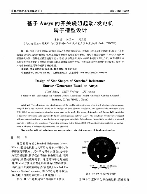
基于Ansys的开关磁阻起动/发电机转子槽型设计
如 O 0
O
大 值 在 材 料 允 许 的 范 围 内。 当 转 速 达 到 2 0 / iH 材料 配合 面应 力达 到 40k a转 1 0rmn ̄, 0 0 P , 速 若大 于此转 速 , 填 充 块从 转 子 槽 中脱 出进 入 则
气隙 , 电机损 毁 。
Un I 'I Pl
r pc Eq u 1 al n I 、 O n — 、 v c (
T il I c.I l 2l 一7 I 39 Jll -1
结果 分别 如 图 6 图 7所示 。 、
A SI 】 ieIinI 【 c SI l ir r Equ i a c n l St ss  ̄ l re
20 0~ 00 0rr n内 变化 时 , 充块 与转 子 槽 0 2 0 a /i 填
配 合面 处应 力 随转 速 呈 指数 上 升 趋 势 , 应力 最 且
热场分析 中首次提 出 厂多场联合有 限元仿真 的温度场分析方法 。为开关磁阻 电机槽型 的设计提供 了参考 , 并 对两种槽 型的适 用场合提供了理论依据 。
关 键 词 : 关 磁 阻起 动 / 电 机 ;转 子 槽 型 ;有 限 元 分 析 开 发 中 图分 类 号 : M 32 T 5 文 献标 志 码 : 文 章编 号 :6 36 4 (0 2 0 0 10 T 0 : M 32 A 17 — 0 2 1 ) 1 0 — 5 5
ao( RS G)w saa zd ae ntea a s f nt e m n s ua o ,w pi zds t t c rso S t S / r a nl e .B sdo n l i o i l et i lin toot e l r t e f R y h ys f e e i m t mi o su u
- 1、下载文档前请自行甄别文档内容的完整性,平台不提供额外的编辑、内容补充、找答案等附加服务。
- 2、"仅部分预览"的文档,不可在线预览部分如存在完整性等问题,可反馈申请退款(可完整预览的文档不适用该条件!)。
- 3、如文档侵犯您的权益,请联系客服反馈,我们会尽快为您处理(人工客服工作时间:9:00-18:30)。
T o r q u e An a l y s i s o f S w i t c h e d Re l u c t a n c e Mo t o r B a s e d o n An s o f t
< 设 计分新
—
z ≯ ∞
I
够特 宴
彭德奇, 等 2 0 1 4 / g  ̄ 4 2 鲞 葶 期
基
基 于 AN S OF T的 开 关 磁 阻 电动 机 转 矩 分 析
彭德奇 , 李华柏 , 谭 平
( 1湖南铁道 职业技术 学院, 湖南株 洲 4 1 2 0 0 1 ; 2中国兵器工业集团江麓机 电科技有限公司 , 湖南湘潭 4 1 1 1 0 0 )
摘 要: 基于工程电磁场有限元分析软件 A n s o f t , 采 用全场域的分析方法, 对开关磁阻电动机的磁场分布 、 瞬态 特性等进行了仿真分析与研究 , 主要就开关磁 阻 电动机 的气 隙、 定转子 极弧 、 导通角对 转矩 的影 响作 了详 细 的研 究, 研究结果表明合理的电机结构尺寸及导通角可 以较好地抑制 电机 的转矩脉动 。 关键词 : 有限元分析软件 ; 开关磁阻 电动机 ; 转矩脉动 ; 导通角
Abs t r a c t : Th e s i mu la t i o n a n a l y s i s a n d r e s e a r c h o f t h e ma g n e t i c ie f l d d i s t r i b u t i o n a n d t r a n s i e n t c h a r a e t e r i ti o c s o f s w i t c h e d r e l u c t a n c e mo t o r we r e c a r r i e d o u t b a s e d o n An s l f n u s i n g t h e d o ma i n a n ly a s i s me t h o d An d a d e t a l i e d tu o d y ma i n l y o n t h e mo t o r a i r g a p , t h e s t a t o r a n d r o t o r p o l e a r c a n d c o n d u c t i o n a n g l e S i n lu f e n c e o n t o r q u e wa s ma d e T h e r e s e a r c h r e s u l t s
2 C h i n a No r t h I n d u s t r i e s Gr ou p C o r p o r a t i o n J i a n g l i u Ma c h i n e r y a n d
E l e c t r o n i c s G r o u p C o, L t d ,Xi a n g t a n 41 1 1 0 0, C h i n a )
1
. .
饱 和的磁路, 很难得 到精 确 的电机解析 式…。在研
—
a ( i …i.一. i
—
究S R M转矩脉 动的方法 中, 其中一个重要的方法就 是 利用有限元法对 S R M磁场进行 分析 , 这种方法计
算 速度快 , 具有 一定精度 。本文将利用 A n s o f t 有 限 元 分析软件对 非线 性 的 S R M 的磁场 分布 、 磁化曲 线、 电感以及瞬态转矩进行分析与计算 , 在此基础上 对气 隙、 定转子极弧 、 开关角对转矩 的影 响进行仿真 分析 , 为S R M的优化设 计提供可靠依据 。
s h o w t h a t r e a s o n a b l e s t r u c t u r e s i z e a n d c o n d u c t i o n a n l g e c a n e f e c t i v e l y s u p p r e s s t h e m o t o r t o r q u e r i p p l e K e y w o r d s : A n s l; f n s w i t c h e d r d u c t a n c e mo t o r( S R M) ; t o r q u e r i p p l e ; c o n d u c t i o n a n le g
吲
言
开关 磁阻电动机 ( 以下 简称 S R M) 具 有典 型 的
响
时
川 ㈦
1 2转矩方程
双 凸极结构和固有 的供电方式 , 使得 S R M的转矩脉
动 非常突出。由于 S R M不 规则 的气 隙和 局部高度
根据机 电能量转换原理 , S R M稳态 运行时 电磁 转矩 可表示 … :
PENG De —q i , L 1 Hu a—b o , T AN 。
( 1 Hu n a n Ra i l w a y P r o f e s s i o n a l T e c h n o l o g y C o l l e g e ,Z h u z h o u 4 1 2 0 0 1 , C h i n a;