力士乐比例减压阀中文说明书
德国rexroth阀Z2FS6外形尺寸与说明
6011431857 SID-UV1ZB 6111431022 SID-UV1ZC 6012431877 SID-UV1ZBB 6011431869 SID-UV1ZP-RASTA 6112431050 SID-UV1ZP-RASTA 6012431883 SID-UV1ZP-RASTB 1015300205 STANDFUSSDREHBARRAL9006P 1016786000 STANDFUSSEINFACHA 6301106065 T-06N/SC 6301262039 T-62N/SB 6301167054 T-67N/SB 6301268028 T-68NC 6402169038 T-69N(KA)/SB 6301269031 T-69N/SC 6116469043 TI2-A1ZKSB 6116469068 TI2-A1ZKSP 产品描述 Z2FS 型阀门采用夹层板设计,是一种双节流止回阀。它用于一个或两个执行器端口的主流量或先导流量 限制。 两个彼此对称对齐的节流止回阀在一个方向上流动并允许在相反方向上的自由回流。 在供应节流的情况下,液压流体通过通道 A6 经由阀座(2)和节流阀芯(3)形成的节流点(1)引导至致 动器 A6。节流阀芯(3)可以通过固定螺丝(4)轴向调节,以调节节流点(1)。 来自致动器 A?的液压流体返回流动使阀座(2)在节流阀芯(3)的方向上抵靠弹簧(5)移动,并且使得 无阻碍的流动作为止回阀。根据安装位置,可能在供应或排放中发生节流效应。 主流限制(版本“2Q”)
(二)施工作业
安装施工必须小心,切忌撞击脆性材料制作的阀门。
安装前,应将阀门作一检查,核对规格型号,鉴定有无损坏,尤其对于阀杆。还要转动几下,看是否歪斜, 因为运输过程中,最易撞歪阀杆。还要清除阀内的杂物。
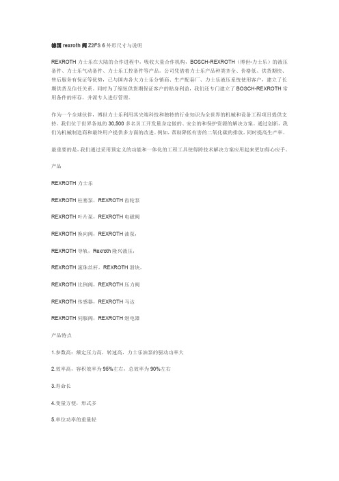
rexroth RE 18702型号比例流量控制阀说明书
Proportional flow control valve,with integrated pressure compensatorFeatures▶Mounting cavity R/UNF-16-03-0-06▶Direct operated proportional valve for controlling the flow size▶Operation by means of proportional solenoid with central thread and detachable coil ▶Rotatable solenoid coil▶With concealed manual override▶Screwable manual override with star handle, optionalContentsFeatures 1Ordering code, valve types 2Available coils, symbols 3Function 4Technical data 5 ... 6Characteristic curves 7 ... 10Minimum terminal voltage at the coil and relative duty cycle 11Dimensions 12Mounting cavity 13Available individual components 14Further information 14▶Size 3▶Component series A▶Maximum operating pressure 350 bar▶Maximum flow 120 l/minRE 18702Edition: 2016-02Replaces: 05.12H7659Type KUDSR2/14KUDSR | Proportional flow control valve 01Proportional flow control valve, with integrated pressure compensator, direct operatedKUDS 02Maximum operating pressure 350 bar R 03Size 3305Component seriesA 06High Performance and mounting cavity R/UNF-16-03-0-06, see page 13F 07With concealed manual override 2)N9Seal material 08FKM sealsV(other seals upon request) Attention! Observe compatibility of seals with hydraulic fluid used!09Further details in the plain text*010203040506070809KUDSR 3A /F N9V *Type Material no.KUDSR3CA/FN9V R901255657KUDSR3C1A/FN9V R901287409KUDSR3C2A/FN9VR901265879Valve types (without coil) 1)1) Complete valves with mounted coil on request.2)Screwable manual override with star handle "N14"(separate order, material no. R913009058, see page 12).Proportional flow control valve | KUDSR 3/143) Mating connectors, separate order, see data sheet 08006.4)Other voltages upon request.Available coils (separate order) 1)Direct voltage DC 4)Material no. for coil with connector 3)"K4" 03pol (2+PE) DIN EN 175301-803"K40" 02pol K40DT 04-2PA, co. Deutsch"C4"02pol C4/Z30 AMP Junior-Timer 12 V (1.8 A)R901022180R901272648R90102268024 V (1.2 A)R901022174R901272647R901022683Symbols① = Main port 1 (P)② = Main port 2 (T)① = Main port 3 (A)14/14KUDSR | Proportional flow control valveGeneralThe proportional flow control valve is a direct operated screw-in cartridge valve in spool design with integrated pressure compensator. It regulates the flow proportionally to the input signal in a stepless form from main port ① to ②. Any excessive residual flow is led to the tank or to another actuator via port ②.The valve basically consists of housing, control spool,control spring, pressure compensator piston, orifice bush, pressure compensator spring as well as proportional solenoid (1) with central thread and detachable coil.FunctionVersion "C4"Type KUDSR3…①②①FunctionWith de-energized proportional solenoid (1), the control spool that is always pressure-compensated to the actuat -ing forces due to its structural design is held in the initial position by the control spring and blocks the flow between main port ① and ③. By energizing the proportionalsolenoid (1), the control spool is adjusted directly propor -tional to the electrical input signal and, via orifice-type cross-sections (with progressive flow characteristics), adjusts and connects the main ports ① and ③. Due to the integrated pressure compensator piston together with the pressure compensator spring, the pressure drop across the valve is kept constant, independent of the pressures at ①, ② and ③. In case of excessive flow from ①, the pres -sure compensator piston moves to the right and opens the connection ① to ②. In case of de-excitation of the propor -tional solenoid (1), the control spring returns the control spool into its initial position. The entire flow is now directly led from main port ① to main port ②The manual override (2) allows for the adjustment of the valve without solenoid energization.Proportional flow control valve | KUDSR 5/14Technical data(For applications outside these parameters, please consult us!)1)The cleanliness classes specified for the components must be adhered to in hydraulic systems. Effective filtration prevents faults and simultaneously increases the life cycle of the components.Available filters can be found at /filter.Environmental auditsSalt spray test according to DIN 50021h 720Surface protection DC solenoids Coating according to DIN 50962-Fe//ZnNi with thick film passivation Hydraulic fluid Classification Suitable sealing materials Standards Mineral oils HL, HLP FKM DIN 51524Bio-degradable▶Insoluble in water HEES FKM VDMA 24568▶Soluble in waterHEPGFKMfluids, please refer to data sheet 90220 or contact us!▶There may be limitations regarding the technical valve data (temperature, pressure range, life cycle, maintenance intervals, etc.)!▶The flash point of the hydraulic fluids used has to be 40 K above the maximum solenoid surface temperature.▶Bio-degradable: If bio-degradable hydraulic fluids are used that are also zinc-solving, there may be an accumulation of zinc.2)Measured with analog amplifier type RA2-1/10 according to data sheet 95230 (PWM = 100 Hz).6/14KUDSR | Proportional flow control valveTechnical data(For applications outside these parameters, please consult us!)standards ISO 13732-1 and ISO 4413 need to be adhered to!024620406080100135Proportional flow control valve | KUDSR 7/14Characteristic curves(measured with HLP46, ϑoil = 40 ± 5 °C and 24 V coil)Flow in l/min →P r e s s u r e d i f f e r e n t i a l i n b a r →∆p -q V characteristic curve – main port ① to ② (③ open, orifice closed)5010015020025030035010203040506070809010005010015020025030035010203040506070809010001020304050607080901020304050607080901008/14KUDSR | Proportional flow control valveCharacteristic curves: Version "C"(measured with HLP46, ϑoil = 40 ± 5 °C and q V ① = 80 l/min)Load pressure in bar →Load pressure in bar →Command value in % →F l o w i n l /m i n →F l o w i n l /m i n →F l o w i n l /m i n →Regulated flow at main port ③ as a function of the load pressure 3-way function (main port ② open to the tank)Regulated flow at main port ③ as a function of the load pressure 2-way function (main port ② closed)Regulated flow at main port ③ as a function of the command value5010015020025030035010203040506070800501001502002503003501020304050607080010203040506070102030405060708090100Proportional flow control valve | KUDSR 9/14Characteristic curves: Version "C1"(measured with HLP46, ϑoil = 40 ± 5 °C and q V ① = 60 l/min)Load pressure in bar →Load pressure in bar →Command value in % →F l o w i n l /m i n →F l o w i n l /m i n →F l o w i n l /m i n →Regulated flow at main port ③ as a function of the load pressure 3-way function (main port ② open to the tank)Regulated flow at main port ③ as a function of the load pressure 2-way function (main port ② closed)Regulated flow at main port ③ as a function of the command value0501001502002503003501020304050600501001502002503003501020304050600102030405010203040506070809010010/14KUDSR | Proportional flow control valveCharacteristic curves: Version "C2"(measured with HLP46, ϑoil = 40 ± 5 °C and q V ① = 40 l/min)Load pressure in bar →Load pressure in bar →Command value in % →F l o w i n l /m i n →F l o w i n l /m i n →F l o w i n l /m i n →Regulated flow at main port ③ as a function of the load pressure 3-way function (main port ② open to the tank)Regulated flow at main port ③ as a function of the load pressure 2-way function (main port ② closed)Regulated flow at main port ③ as a function of the command value24687080901001101201,010122,01,21,41,61,8048127080901001101200,416201,40,60,81,01,2Ambient temperature in °C →Ambient temperature in °C →R e q u i r e d m i n i m u m v o l t a g e a t t h e c o i l (1) →R e q u i r e d m i n i m u m v o l t a g e a t t h e c o i l (1) →R e d u c e d d u t y c y c l e f o r I m a x (1.8 A ) i n % (2) →R e d u c e d d u t y c y c l e f o r I m a x (1.2 A ) i n % (2) →A d m i s s i b l e c o n t i n u o u s a p p l i c a t i o n o f c u r r e n t i n A w i t h 100 % d u t y c y c l e (3) →A d m i s s i b l e c o n t i n u o u s a p p l i c a t i o n o f c u r r e n t i n A w i th 100 % d u t y c y c l e (3) →▶Version "G12"▶Version "G24"Admissible working range dependent on the ambient temperatureLimited valve performanceMinimum terminal voltage at the coil and relative duty cycleDimensions (dimensions in mm)①② = Main port 2 (T)③ = Main port 3 (A)LS = Location shoulder1Mating connector without circuitry for connector "K4"(separate order, see data sheet 08006)2Space required to remove the mating connector3SW36, tightening torque M A = 165+15 Nm4Dimension for "K4" mating connector, without circuitry 5Dimension () for "K4" mating connector, with circuitry 6Mating connector for connector "K40"(separate order, see data sheet 08006)7Mating connector for connector "C4"(separate order, see data sheet 08006)8Nut, tightening torque M A = 5+2 Nm9Coil (separate order, see page 3)10Concealed manual override "N9"11Screwable manual override with star handle "N14"(separate order, see page 3)Mounting cavity R/UNF16-03-0-06; 3 main ports; thread 1 5/16-12 UN-2B (dimensions in mm)1)① = Main port 1 (P)② = Main port 2 (T)③ = Main port 3 (A)LS = Location shoulderAll seal ring insertion faces are rounded and free of burrsBosch Rexroth AG HydraulicsZum Eisengießer 197816 Lohr am Main, Germany Phone +49 (0) 93 52 / 18-0***************************** www.boschrexroth.de© This document, as well as the data, specifications and other information set forth in it, are the exclusive property of Bosch Rexroth AG. It may not be reproduced or given to third parties without its consent.The data specified above only serve to describe the product. No statements concerning a certain condition or suitability for a certain application can be derived from our information. The information given does not release the user from the obligation of own judgment and verification. It must be remembered that our products are subject to a natural process of wear and aging.Available individual componentsItem Denomination Material no.910NutR900029574920Seal ring for pole tube R900002507999Seal kit of the valve R961003236AManual override "N14"R913009058Coils, separate order, see page 3.999A920910Further information▶Control electronics:–Analog amplifier module type VT-MSPA1…Data sheet 30223 –Plug-in proportional amplifier type VT-SSPA1…Data sheet 30116 –Analog amplifier type RA…Data sheet 95230 –BODAS control unit type RC…Data sheet 95200▶Selection of the filters/filterBosch Rexroth AGHydraulicsZum Eisengießer 197816 Lohr am Main, Germany Phone +49 (0) 93 52 / 18-0***************************** www.boschrexroth.de © This document, as well as the data, specifications and other information set forth in it, are the exclusive property of Bosch Rexroth AG. It may not be reproduced or given to third parties without its consent.The data specified above only serve to describe the product. No statements concerning a certain condition or suitability for a certain application can be derived from our information. The information given does not release the user from the obligation of own judgment and verification. It must be remembered that our products are subject to a natural process of wear and aging.NotesNotes。
ZDR10DA2-5X150Y力士乐减压阀

ZDR10DA2-5X150Y力士乐减压阀ZDR10DA2-5X/150Y力士乐减压减压阀是常开的,其出口压力由调压弹簧设定。
减压阀可将进口压力降至出口压力。
在液压系统中,如果不同设备需要不同压力,则可以使用减压阀·当出口压力升高时,作用在控制活塞左端面上油压力变大,控制活塞向右移动,阀口变小,压降增大,从而使出口压力降至设定值。
在滑阀式结构中,也可以采用控制边结构,以缓慢增加开口量,从而使减压阀具有较高调压精度。
直动式3位4通比例方向控制阀带输入电压控制信号士10VDC公称流量32L/min中位机能O型,可以锁止油缸,换向位置精度高最高工作压力315bar(4550psi)采用氟橡胶密封,耐腐蚀最大流量80L/min设计系列号2X=23,22,21,20……ZDR10DA2-5X/150Y于冶金,注塑机等高端液压系统的流量方向,速度,压力等的综合精密控制。
减压阀是一种自动降低管路工作压力的专门装置,它可将阀前管路较高的液体压力减少至阀后管路所需的水平。
这里的传输介质主要是水。
减压阀广泛用于高层建筑、城市给水管网水压过高的区域、矿井及其他场合,以保证给水系统中各用水点获得适当的服务水压和流量。
鉴于水的漏失率和浪费程度几乎同给水系统的水压大小成正比,因此减压阀具有改善系统运行工况和潜在节水作用,据统计其节水效果约为30%。
减压阀的构造类型很多,以往常见的有薄膜式、内弹簧活塞式等。
减压阀的基本作用原理是靠阀内流道对水流的局部阻力降低水压,水压降的范围由连接阀瓣的薄膜或活塞两侧的进出口水压差自动调节。
力士乐压力阀ZDR10DA2-5X/150Y,ZDR10DA2-5X/210Y微欣直接搜索添加本馆名。
力士乐REXROTH减压阀是通过调节,将进口压力减至某一需要的出口压力,并依靠介质本身的能量,使出口压力自动保持稳定的阀门。
从流体力学的观点看,减压阀是一个局部阻力可以变化的节流元件,即通过改变节流面积,使流速及流体的动能改变,造成不同的压力损失,从而达到减压的目的。
德国力士乐液压阀 DBGT 的说明说明书

德国rexroth阀DBGT的的液压阀块说明力士乐致力于为各类机械和系统设备提供安全、精准、高效以及高性价比的传动与控制技术。
公司融合全球的应用经验,研发创新的产品,为行走机械、机械应用与工程、工厂自动化及可再生能源每一个细分市场的客户量身定制系统解决方案及服务。
博世力士乐同时为客户提供各种液压、电子传动与控制、气动、齿轮、线性传动及组装技术.重点产品低成本、低排放——博世力士乐液压风扇驱动系统全球气候的异常变化让世人的目光再次聚焦到节能和减排这两个敏感话题上,各国对于废气排放的标准已经变得越来越严格。
力士乐的液压风扇驱动系统凭借其出色的降噪、散热及节能效果,使城市公交客车在降低能耗的同时,实现更低的排放等级。
与传统的液压风扇系统相比,力士乐液压风扇驱动系统可以节省最高达5%的油耗,并降低3分贝以上噪音。
高能效、高产能——博世力士乐液压抽油机当前中国抽油机市场以机械游梁式抽油机为主,但随着市场的发展,对能效和生产力的要求进一步提高。
博世力士乐顺应市场需求,推出了液压抽油机。
不同于机械抽油机,液压抽油机可以通过直接输入参数来调节冲次和冲程,轻松便捷地根据条件变化进行调整。
与传统解决方案相比,力士乐液压抽油机可以节省25%的能耗,并使生产力提高15%。
高能效、低噪音——博世力士乐Sytronix混合动力系统低能耗可以降低设备的运作成本,提高市场竞争力。
博世力士乐新型混合动力系统Sytronix可以实现设备运行时只消耗实际所需能源的目标。
通过优化泵和电机驱动组合达到快速响应来提高性能,以扩展液压控制功能。
力士乐Sytronix混合动力系统可以节省最高达80%的能耗,并降低20分贝以上噪音。
绿色、可靠——博世力士乐风能齿轮箱中国的风力发电机市场已经位居全球前端地位,计划到2015年,风能装机容量将上升到大约10万MW。
博世力士乐作为全球很大的独立风能主齿轮箱供应商,为风力发电机提供全套传动与控制技术。
为了更好的支持中国风力发电事业,博世力士乐于2008年在北京建立了全新的生产基地。
l力士乐比例分流阀2

3
M1
M 4
3
X
A
X
B
6
1
P
MHFAN型
5 S
X-X
带附加内置式压力补油阀
RC 64 582/05.03 | MH2FA
行走机械液压 | 博世力士乐 /14
功能说明,剖面图
带自由轮回路的分流阀(可切换) 从原理上来讲,该分流阀的功能与不带自由轮回路分 流阀的功能相同。不过该阀附装有控制阀芯()和阀芯 复位弹簧(8)。 控制阀芯()由复位弹簧(8)维持在起始位置。P口的流 量环绕控制阀芯()直接流入油口A和B。 操作控制阀芯()可选择通过Pst口(10)进行液控或经换 向阀()及电磁铁(11)进行电控制。
3
8
4 0
16
1
8
4
0
0
40
60
80
100
进油流量qv,p%→
p-qv-关闭差速阀时的工作曲线
,0
通径1
1,5
1,0
通径18,,
0,5
3
0
50
100
150
00
50
300
进油流量qv,p%→
0,6 0,8 1,0 1, 1,5 ,0 3,0
节流孔-特性曲线
450 300
00
3 补偿节流孔的螺堵 4 测量油口的螺堵 5 分流阀固定孔 6 “无压力补油阀”的结构尺寸 带压力补油阀(订货型号“H”)的结构尺寸
RC 64 582/05.03 | MH2FA
无自由轮回路的分流阀(尺寸单位:mm)
通径 18,,3
P
14,5
10
M1; 18
03
81
M1
Rexroth 先導式減壓閥 ZDR 10 型 说明书
4R 83/5Industrial HydraulicsElectric Drives and ControlsLinear Motion andAssembly TechnologiesPneumaticsService AutomationMobile HydraulicsZDR 10 VA5-3X/...Y...RC 26 861/02.0312.02ZDR 10103X315 bar100 L/min©2003by Bosch Rexroth AG,Industrial Hydraulics,D-97813Lohr am MainDIN 24 340 A ISO 4401 CE TOP-RP 121 H 4 4VA, VB1 1 22 23 344Pressure valves type ZDR10V are pilot operated pressure valves ofsandwich plate design.They are used to reduce a system pressure.The valves consist of the cartridge(1)and a housing(2).The reducedpressure is set via the adjustment element(4).Version"VP"At rest,the valve is normally open,and fluid can flow unhinderedfrom port P2to port P1.Pressure in port P1is simultaneously alsopresent at the main spool(6),via orifice(5),and on the spring loadedinner side of the main spool(6).The pressure is also present viaorifice(9)on the pilot poppet(8).When the pressure in port P2exceeds the pressure level set at thespring(7),then the pilot poppet(8)opens.Pressure fluid then flowsfrom the spring loaded inner side of the main spool(6)via orifice(9),and the pilot poppet(8)into the spring chamber(10)to tank.Themain spool(6)moves into the control position and holds the pressureset at spring(7)in port P1constant.Pilot oil drain from spring chamber(10)is via port TA.Versions"VA"and"VB"For versions VA and VB,the pressure is reduced in ports A2or B2.In order to allow free reverse flow from portA2toA1,or B2to B1anoptional check valve may in included(this is not possible for versionVP).An optional pressure gauge connection(3)allow the secondarypressure to be monitored.ቢ = ባ =ZDR 10V1 2 4"VP"P2 P1P1 6 56 98P2 7 86 98 10 67 P1 TA Y10"VA" "VB"VA VB A2 B2A2 A1 B2 B1VP34100205031540608010015020025030001002010406080203040508910020406080305101520251320100205406080101520253045100204060800,30,40,50,6672)RE 50 070 RC 50 076 RC 50 081HLP46 ϑoil = 40˚C ± 5˚Cb a r →L/min →L/min →p A -q V -∆p p E -p A - p A -q V -∆p min -q V -L /m i n →L/min →p A -q V - 50 barb a r →∆p-q V -L/min →L/min →b a r →b a r →1P2 P1 VP 2A1 A2 VA 3B1 B2 VB 4A2 A1 VA 5B2 B1 VB6 p = 50bar7 p = 250bar 89419 1 :(852) 2262 5100 :(852) 2786 0733:@ :Bosch Rexroth AG Industrial HydraulicsD-97813 Lohr am MainZum Eisengießer 1 • D-97816 Lohr am Main Telephone : 0 93 52/18-0Telefax : 0 93 52/18-23 58 • Telex : 6 89 418-0eMail : documentation@boschrexroth.de Internet : www.boschrexroth.demm。
Festo VPPL比例压力阀操作手册说明书
1适用文件2安全2.1安全注意事项–仅在原装状态下使用产品,请勿擅自进行改动。
–请仅在技术状态完好的情况下使用本产品。
–仅使用符合规格说明的介质 è 技术参数。
–禁止使用液体或气体工作。
–请注意使用场所的环境条件。
–本阀仅允许按照标记的流向使用。
–本产品可能产生高频干扰,在居住环境内可能需要采取抗干扰措施。
2.2按规定使用按照规定,比例压力调节阀 VPPL 只能用于根据给定的额定值按比例调节压力。
带和不带外部先导气源的比例压力调节阀 VPPL 的法兰安装型只能与减压阀PREL 一起使用。
2.3专业人员的资质关于产品的一切工作仅允许由具备资质的专业人员进行,这些专业人员对工作进行评估并识别出危险。
专业人员拥有处理电气气动控制技术的知识和经验。
2.4UL/CSA 认证本章节信息和产品上的 UL 检验标志,均表示符合美国和加拿大Underwriters Laboratories Inc. 公司 (UL) 的认证条件 公司的的认证条件。
3其他信息–技术问题请联系当地 Festo 联络人 è .–附件和备件 è /catalogue。
4产品概况4.1功能减压阀 PREL 的输出压力被接通到比例压力调节阀 VPPL 的工作接口。
通过集成的压力传感器确定输出压力,并与设定值进行对比。
存在偏差时,VPPL 对PREL 的控制器进行控制,直至输出压力达到设定值。
安全设置电缆断裂时,输出压力下降至 0 MPa。
当设定值信号小于满量程的 1 % 时,VPPL 将其解析为 0 V。
这种情况下,工作压力将被设置为环境压力。
4.2结构比例压力调节阀 VPPL 有三种版本:–法兰安装型 VPPL-3Q–带外部先导气源的法兰安装型 VPPL-3Q-Z –管式 VPPL-3L VPPL-3Q/VPPL-3Q-Z插图 1:VPPL-3Q/VPPL-3Q-ZVPPL-3L插图 2:VPPL-3L4.2.1显示元件和操作元件插图 3:显示元件和操作元件4.2.2连接元件表格 4:“实际值输出”接口的针脚分配表格 5:“设定值输入/电源”接口的针脚分配5装配5.1安装前提条件:–管路系统无压力,且未输送介质。
比例阀中文说明书
①同时摁下达 3 秒以上
■ 使用注意事项
! 注意
1. 本产品,在控制状态时,由于停电等异常情况引起电源被切断,能在短时间内保持 2 次侧的出口压力。 当 2 次侧为大气开放的状态时,停电后空气还会继续排放,使用时请充分注意。
2. 本产品,在通电状态下停止供给压力时,内藏的电磁阀持续动作,可能会引发噪声。当停止供气时,请 务必同时切断电源。
电流型 电压型
4~20mADC (ITV10※※-01,ITV20※※-01,ITV30※※-01) 0~20mADC (ITV10※※-11,ITV20※※-11,ITV30※※-11) 0~5VDC (ITV10※※-21,ITV20※※-21,ITV30※※-21) 0~10VDC (ITV10※※-31,ITV20※※-31,ITV30※※-31)
质量
约 250g(无附属品){ITV1000}
约 350g(无附属品){ITV2000}
约 620g(无附属品){ITV3000}
注1) 输出压力 0.1MPa 规格最大供给压力为 0.2MPa。
注2) 超出规格范围时,会发生破损,请注意。
3
■ 配线方法 电缆与本体的端子连接时,请以下记的形式进行配线。
输出压力% 输出压力%
输入信号
输入信号
■ 显示输出
显示用的输出电压依据下表所示。本产品所连接的计测器件,其所使用的负载阻抗请确保在 1kΩ 以上。另
外,此输出电压需增幅使用时,请同样考虑设计负载阻抗在 1kΩ 以上。
型号
输出压力(MPa)
显示用输出电压(VDC) 注)
ITV※01※-※1
0.005~0.1
1各部分名称外形尺寸安装孔up键键配线电缆接线端子设定键set键down键键安装托架选配右弯出线型电缆接线端子显示用led4芯sup接口压力表用接口out接口外形尺寸安装孔安装孔安装托架安装托架选配选配直线出线型电缆接线端子4芯右弯出线型电缆接线端子4芯安装孔2规格供给压力注1设定压力01mpa但最大为1mpa000501mpaitv1011itv2011itv3011设定压力000505mpaitv1031itv2031itv3031000509mpaitv1051itv2051itv3051约200lminanritv1000供给压力
Rexroth 压力调节阀 EV07 说明书
产品手册2Bosch Rexroth AG | Pneumatics压力调节阀 → 电气比例阀补充性产品,系列 EV07粗体字标识的材料编号从德国的中心仓库起即可使用,详细信息请见购物篮气动产品-目录,在线PDF,制定于 2011-11-05, © Bosch Rexroth AG,保留更改权利3Bosch Rexroth AG | Pneumatics压力调节阀 → 电气比例阀E/P压力调节阀, 系列 EV07▶ Qn= 800 l/min ▶ 压缩空气 接口 出口: G 1/4 ▶ 电子连接: 多芯插头, EN 175301-803, A型 ▶ 信号连接: 输入和输出, 多芯插头, EN 175301-803, A型 ▶ 伺服阀(先导阀)补充性产品粗体字标识的材料编号从德国的中心仓库起即可使用,详细信息请见购物篮气动产品-目录,在线PDF,制定于 2011-11-05, © Bosch Rexroth AG,保留更改权利P561_028结构特点提动阀控制方式模拟量合格证书CE认证环境温度 最小值/最大值+5°C / +50°C 最低/最高介质温度+5°C / +50°C 介质压缩空气颗粒大小 max.50 µm 压缩空气中的最大含油量0,1 mg/m³Qn800 l/min 安装位置垂直进气压力见下表滞环0,03 bar 工作电压DC 24 VDC电压公差-20% / +20%允许的脉动5%功率消耗 max.0,2 A 防护等级 带有接线盒 / 插头IP 54压缩空气 接口 人口G 1/4压缩空气 接口 出口G 1/4压缩空气连接 排气G 1/4重量2 kg材料:外壳铝材-压铸件密封丙烯树胶额定流量Qn,当工作压力为7 bar、二次压力为6 bar及Δp = 0.2 bar时4Bosch Rexroth AG | Pneumatics压力调节阀 → 电气比例阀E/P压力调节阀, 系列 EV07▶ Qn= 800 l/min ▶ 压缩空气 接口 出口: G 1/4 ▶ 电子连接: 多芯插头, EN 175301-803, A型 ▶ 信号连接: 输入和输出, 多芯插头, EN 175301-803, A型 ▶ 伺服阀(先导阀)补充性产品粗体字标识的材料编号从德国的中心仓库起即可使用,详细信息请见购物篮气动产品-目录,在线PDF,制定于 2011-11-05, © Bosch Rexroth AG,保留更改权利D561_0103) 螺纹接口 1 - 3 = G1/4 ISO 228/1:2000D561_020a)额定输入值 b)实际输出值 E/P 压力调节阀是根据相似的电流值来调节压力。
4WRZE力士乐比例阀样本
B → T:qV /2 A → T:qV B → T:堵塞
A → T:qV
注意:符号为 W6-,W8-,W9-,W6A 时,A → T 和 B → T 的连接距离在切换位置 "0" 的各公称剖面的 2 % 以下。
4/28 Bosch Rexroth AG Hydraulics
.WRZ;.WRZE;.WRH RC 29115/08.13
= 无代码 =E
= ET =T
RC 29115/08.13 .WRZ;.WRZE;.WRH
Hydraulics Bosch Rexroth AG
3/28
*
M = V = 无代码 = D3 1)=
A1 = F1 = 无代码 =
K4 1, 4)=
K31 1, 4)=
1)不适用于型号 4WRH 2)适用于型号 "J" → "N",不适用于 "N9"
不带电气位置反馈,不带/带集成电子 RC 29115/08.13 1/28
元件(OBE)的先导式二位四通,
替代对象:10.05
三位四通和二位五通,
三位五通比例方向阀
型号 .WRZ…,.WRZE… 和 .WRH…
规格 10 至 52 组件系列 7X 最大工作压力 350 bar 最大流量 2800 l/min
带液压操作
型号 4WRH…-7X./… 和 型号 4WRH 52…-7XF/…
AB
a
a 0b
b
X
PT
X
型号 5WRH 52…-7X. AB
a
a 0b
b
X
RPT
X
X = 外部 Y = 外部
X = 外部 Y = 外部
- 1、下载文档前请自行甄别文档内容的完整性,平台不提供额外的编辑、内容补充、找答案等附加服务。
- 2、"仅部分预览"的文档,不可在线预览部分如存在完整性等问题,可反馈申请退款(可完整预览的文档不适用该条件!)。
- 3、如文档侵犯您的权益,请联系客服反馈,我们会尽快为您处理(人工客服工作时间:9:00-18:30)。
力士乐比例减压阀中文说明书
力士乐比例减压阀功能:通过比例电磁铁设置A或B中的压力。
压力的大小取决于电流。
线圈(5、6)断电后,控制阀芯(2)将通过压缩弹.簧(8)保持在中心位置。
油口A和B连接到T,以便液压油可以不受阻挡地流入油箱。
通过为比例电磁铁(例如线圈“a"(5))通电,压力测量阀芯(3)和控制阀芯(2)将向右移动。
这样将通过具有渐进流体特性的节流横截面,打开从P到B及从A到T的连接。
在通道B中形成的压力通过压力测量阀芯(4)的表面作用于控制阀芯,抵抗线圈磁力。
压力测量阀芯(4)受线圈“b”支撑。
如果压力超过线圈“a”上设置的值,将逆线圈磁力方向回推控制阀芯(2),并建立B与T的连接,直到重新达到调定压力。
压力与线圈电流成比例。
当线圈关闭时,控制阀芯(2)在压缩弹簧(8)的作用下返回到中心位置。
可选手动应急操作元件(9、10)可在线圈不通电的情况下移动控制阀芯(2)。
德国REXROTH力士乐比例减压阀特征
用于控制压力和流向的直动式比例阀
通过带有中心螺纹和可拆卸线圈的比例电磁铁进行操纵
用于底板安装:孔图按ISo4401
手动应急操作,可选
弹簧定中的控制滑板
带集成电子元件(OBE)的型号3DREPE
带外部电子元件的型号3DREP
型号DRSandZDRS
比例减压阀,先导式,有直流马达操作
规格6
安装面按ISO4401
用于降低系统压的阀,有溢流功能
直流马达操作
力士乐减压阀/力士乐比例减压阀
底板安装
作为叠加阀
型号3DRE(M)和3DRE(M)E
比例减压阀,先导式
规格10和16
安装面按DIN24340A型和ISO4401
用于降低系统压力的阀
比例电磁铁操作
底板安装
用于3DREEand3DREME的集成电控器(OBE)
型号DRE
比例减压阀,先导式
规格6和10
规格6:安装面按ISO4401
规格10:安装面按ISO5781-AG-06-2-A
用于降低系统压力的阀
比例电磁铁操作
通过电磁铁电枢位置进行调节
DREBE型的集成电控器(OBE)
型号DRE(M)和DRE(M)E
比例减压阀,先导式
规格10至32
安装面按DIN24340D型
用于降低系统压力的阀
比例电磁铁操作
底板安装
线性压力/指令值特性曲线
用于DREM和DREME型的ZUi大减压功能
可选单向阀,在A和B油口之间
集成电控器(OBE),用于DREE和DREME 型号(Z)DREandZDREE10
比例减压阀,先导式
规格6和10
安装面按DIN24340A型和ISO4401
力士乐比例减压阀中文说明书。