流体力学与传热 :2-2-6 Pump priming
(完整版)流体力学与传热学试题及答案

流体力学与传热学试题及参考答案一、填空题:(每空1分)1、对流传热总是概括地着眼于壁面和流体主体之间的热传递,也就是将边界层的 和边界层外的 合并考虑,并命名为给热。
答案:热传导;对流传热2、在工程计算中,对两侧温度分别为t1,t2的固体,通常采用平均导热系数进行热传导计算。
平均导热系数的两种表示方法是 或 。
答案;221λλλ+=-;221t t +=-λ3、图3-2表示固定管板式换热器的两块管板。
由图可知,此换热器为 管程,管程流体的走向为 或 。
1 2 3图3-2 3-18 附图答案:4;2→4 →1→5→3;3→5→1→4→24、黑体的表面温度从300℃升至600℃,其辐射能力增大到原来的 倍. 答案: 5.39分析: 斯蒂芬-波尔兹曼定律表明黑体的辐射能力与绝对温度的4次方成正比, 而非摄氏温度,即4273300273600⎪⎭⎫⎝⎛++=5.39。
5、3-24 用0.1Mpa 的饱和水蒸气在套管换热器中加热空气。
空气走管内,由20℃升至60℃,则管内壁的温度约为 。
答案:100℃6、热油和水在一套管换热器中换热,水由20℃升至75℃。
若冷流体为最小值流体,传热效率0.65,则油的入口温度为 。
答案:104℃ 分析: ε=2020751--T =0.65 ∴1T =104℃1 2 37、因次分析法的基础是 ,又称因次的和谐性。
答案:因次的一致性8、粘度的物理意义是促使流体产生单位速度梯度的_____________。
答案:剪应力9、如果管内流体流量增大1倍以后,仍处于滞流状态,则流动阻力增大到原来的 倍。
答案:210、在滞流区,若总流量不变,规格相同的两根管子串联时的压降为并联时的 倍。
答案:411、流体沿壁面流动时,在边界层内垂直于流动方向上存在着显著的_______________,即使____________很小,____________仍然很大,不容忽视。
答案:速度梯度;粘度;内摩擦应力 12、雷诺数的物理意义实际上就是与阻力有关的两个作用力的比值,即流体流动时的______ 与__ ____ 之比。
流体力学与传热英文习题(64学时)

Problems of Fluid Flow and Heat Transfer for Unit Operations of Chemical EngineeringZHONG Li(College of Chemistry and Chemical Engineering, South China University of Technology)1. Water is pumped at a constant velocity 1m/s from large reservoir resting on the floor to the open top of an absorption tower. The point of discharge is 4 meter above the floor, and the friction losses from the reservoir to the tower amount to 30 J/kg. At what height in the reservoir must the water level be kept if the pump can develop only60 J/kg?2. The fluid (density 1200 kg/m3 ) is pumped at a constant rate 20 m3 /h from the large reservoir to the evaporator. The pressure above the reservoir maintains atmosphere pressure and the pressure of the evaporator keeps 200 mmHg (vacuum). The distance between the level of liquid in the reservoir and the exit of evaporator is 15 meter and frictional loss in the pipe is 120 J/kg not including the exit of evaporator, what is the pump effective work and power if the diameter of pipe is 60 mm?3. Water comes out of the pipe (Φ108x4 mm), as shown in Fig. The friction loss of the pipeline which does not cover the loss at the exit of pipe can be calculated by the following equation:h f =6.5U2where U is the velocity in the pipe, finda. water velocity at section A-A'.b. water flow rate, in m3 /h.4. Water passes through the variable pipe. The velocity in the small pipe is 2.5 m/s. The vertical glass tubes are inserted respectively at the section A and B to measure the pressure (see fig.) If the friction loss between two section is 15 J/kg, what is the water column difference between two glass tubes? By the way, draw the relative liquid column height of two tubes in the Fig.5. A centrifugal pump takes brine (density 1180 kg/m3 , viscosity 1.2 cp) from the bottom of a supply tank and delivers it into another tank. The line between the tanks is 300 m of 25 mm diameter pipe (inner diameter). The flow rate is 2 m3 /h. In this line, there are two gate valves, four elbows (90o ) and one return bend, what is the friction loss if the roughness of pipe is 0.025 mm?6. The orifice meter (diameter of orifice 0.0001 m) is installed for measuring the flow rate. The indicating liquid of orifice is mercury if U shape pressure gauge reading is 0.6 meter and orifice coefficient can be taken as 0.61, what is the flow rate of water?7. Water flows through a pipe with a diameter di 100 mm as shown in figure.a. when the valve is closed, R is 600 mm and h equals 1500 mm. While the valve opens partially, R=400 mm and h=1400 mm, f=0.00625 (Finning factor) and k c =0.5 (contraction coefficient), what is the flow rate of water, in m3 /h?b. If the valve opens fully, what is the pressure of section 2-2', in N/m2 ? The equivalent length of the valve is1.5 m and the Fanning factor f keeps the same?(ρH2O=1000kg/m3, ρHg=13600kg/m3)8. The rotameter is installed to measure the water flow rate, as shown in figure. If the total length includingequivalent length of pipeline A is 10 m and the reading of rotameter is 2.72 m3 /h, what is the flow rate for pipeline B? (f A =0.0075, f B =0.0045)9. Water is transported by a pump (efficiency of pump 65%) from reactor to higher tank, as shown in Figure. The total equivalent length of pipe is 200 m including all local frictional loss. The pipeline is φ89⨯4.5 mm , theorifice coefficient C o and orifice diameter d o are 0.61 and 20 mm, respectively. Frictional coefficient λis 0.025 and the readings of vacuum gauge in reactor and pressure gauge in tank are 200 mm Hg and 49000N/m2 , respectively.Find:(1) Water mass flow rate, in kg/s when the reading R of U pressure gauge in orifice meter is 600 mm Hg? (ρH2O =1000 kg/m3, ρHg =13600 kg/m3)(2)Effective work of pump, in J/kg?C (density of air 1.205 kg/m3 , viscosity 1x10⁻⁵ Pa.s). Calculate the maximum diameter of particle if the settle obeys the Stoke s’ Law?11. A filter press(A=0.1 m2 ) is used for filtering slurry. The vacuum inside the filter is 500 mm Hg. One liter filtrate can be got after filtering of 5 min and 0.6 more liter filtrate is obtained after 5 more min. How much filtrate will be got after filtering of 5 more min?12. The following data are obtained for a filter press (A=0.0093 m2) in a lab.------------------------------------------------------------------------------------------------pressure difference (kg f /cm2 ) filtering time (s) filtrate volume (m3 )1.05 502.27⨯10-3660 9.10⨯10-33.50 17.1 2.27⨯10-3233 9.10⨯10-3Find1) filtering constant K, q e , t e at pressure difference 1.05 kg f /cm2 ?2) if the frame of filter is filled with the cake at 660 s, what is the end filtering rate (dV/dt)E at P 1.05 kg f /cm2 ?3) compressible constant of cake s?13. A slurry is filtered by a 0.1 m2 filter press at constant pressure if the cake is incompressible. The filter basic equation is as follows:(q+10)2 = 250(t+ 0.4)where q---l/m2 t----minfind (1) how much filtrate is got after 249.6 min?(2) if the pressure difference is double and the resistance of cake is constant, how much filtrate can be obtained after 249.6 min? (cake is incompressible)14. A flat furnace wall is constructed of 120 mm layer of sil-o-cel brick, with a thermal conductivity 0.08 w/(m o C), backed by a 150 mm of common brick, of conductivity 0.8 w/(m o C), the temperature of inner face of the wall is 1400 o , and that of the outer face is 200o C.a. What is the heat loss through the wall in w per square meter.b. To reduce the heat loss to 600 w/m2 by adding a layer of cork with k 0.2 w/(m o C) on the outside of common brick, how many meters of cork are required?15. The vapor pipe (d o=426 mm) is covered by a 426 mm insulating layer (k=0.615 w/m o C). If the temperature of outer surface of pipe is 177 o C and the temperature outside the insulating layer is 38 o C, what are the heat loss per meter pipe and the temperature profile within the insulating layer?16. A steel spherical shell has inside radius r i and outside radius r o. The temperatures inside and outside walls are t i and t o, respectively and the conductivity is k. Derive the equation for heat transfer by conduction.17. Air at the normal pressure passes through the pipe (d i 20 mm) and is heated from 20o C to 100o C. What is the film heat transfer coefficient between the air and pipe wall if the average velocity of air is 10 m/s? The properties of air at 60 o C are as follows:density 1.06 kg/m3 , viscosity 0.02 cp, conductivity 0.0289 w/(m o C), and heat capacity 1 kJ/kg-K18. A hot fluid with a mass flow rate 2250 kg/h passes through a ∅25⨯2.5(outer diameter of pipe⨯ thickness of pipe wall) mm tube. The physical properties of fluid are as follows:k=0.5 w/(m o C), C p =4 kJ/kg-K, viscosity 10-3 N-s/m2 , density 1000 kg/m3 Find:a. Heat transfer film coefficient h i , in w/(m2 -K).b. If the flow rate decreases to 1125 kg/h and other conditions are the same, what is the h i ?c. If the diameter of tube (inside diameter) is decreased to 10 mm, and the velocity u keeps the same as that ofcase a, calculate h i .d. When the average temperature of fluid and quantity of heat flow per meter of tube are 40o C and 400 w/m, respectively, what is the average temperature of pipe wall for case a?e. From this problem, in order to increase the heat transfer film coefficient and enhance heat transfer, what kinds of methods can you use and which is better, explain why?Hint: for laminar flow, Nu=1.86[Re Pr]1/3for turbulent flow Nu=0.023Re0.8 Pr1/319. In a double pipe exchange (Φ23⨯2 mm), the cold fluid (Cp=1 kJ/kg, flow rate 500 kg/h) passes through the pipe and the hot fluid goes through the outside. The inlet and outlet temperatures of cold fluid are 20 and 80 o , and the inlet and outlet temperatures of hot fluid are 150 and 90o , respectively. The h i (film coefficient inside pipe) is 700 w/(m2 o C)and overall heat transfer coefficient U o (based on the outside surface of pipe) is 300w/(m2 o C), respectively. If the heat loss is ignored and the conductivity of pipe wall (steel) is taken as 45 w/(m o C), find:(1) heat transfer film coefficient outside the pipe h o?(2) the pipe length required for counter flow, in m?(3) what is the pipe length required if the heating medium changes to saturated vapor(140 o C) and it condenses to saturated liquid and other conditions keep unchanged?(4) When the exchanger is used for a year, it is found that it cannot meet the need of production (the outlet temperature of cold fluid cannot reach 80o C), explain why?20. Water flows turbulently in the pipe of Φ25⨯2.5 mm shell tube exchanger. When the velocity of water u is 1 m/s, overall heat transfer coefficient Uo (based on the outer surface area of pipe) is 2115 w/(m2 o C). If the u becomes 1.5 m/s and other conditions keep unchanged, Uo is 2660 w/( m2 o C ). What is the film coefficient ho outside the pipe? (Heat resistances of pipe wall and scale are ignored)21. Water and oil pass parallelly through a exchanger which is 1 m long. The inlet and outlet temperatures of water are 15 and 40 o C, and those of oil are 150 and 100 o C, respectively. If the outlet temperature of oil decreases to 80 o C, and the flow rates and physical properties and inlet temperatures of water and oil maintain the same, what is the pipe length of new exchanger? (Heat loss and pipe wall resistance are neglected)22. Air which passes through the pipe in turbulent flow is heated from 20 to 80 o C. The saturated vapor at 116.3 o C condenses to saturated water outside the pipe. If air flow rate increases to 120% of the origin and inlet and outlet temperatures of air stay constant, what kind of method can you employ in order to do that? (Heat resistance of pipe wall and scale can be ignored)23. Water flows through the pipe of a Φ25⨯2.5 mm shell-tube exchanger from 20 to 50 o C. The hot fluid (C p 1.9 kJ/kg o C, flow rate 1.25 kg/s) goes along the shell and the temperatures change from 80 to 30 o C. Film coefficients of water and hot fluid are 0.85kw/(m2 o C) and 1.7 kw/(m2 o C). What is the overall heat transfer coefficient Uo and heat transfer area if the scale resistance can be ignored? (the conductivity of steel is 45w/(m o C).思考问答题1. If the inlet and outlet temperatures of fluids are given, the LMTD of countercurrent flow is always larger than that of parallel-current flow?2. For countercurrent flow, the outlet temperature of cold fluid can be higher than that of hot one.3. The value of overall heat transfer coeff. U is closed to that of larger heat transfer film coeff.4. Dirty overall heat transfer coef. is smaller than clean overall heat transfer coef.5. If h i and h o are 10 and 1000 w/(m2o C), respectively, we should try to increase h o in order to elevate overall heat transfer coefficient U.6. For no phase change, ΔT of 1-2 pass shell-tube exchanger is smaller than LMTD of countercurrent flow.7. Explain simply the advantages of countercurrent flow over parallel-current flow and in what situations, parallel flow should be used.8.Dimensional analysis can directly produce the numerical results without experimental data.9. Decrease of thermal boundary layer thickness can increase h and enhance heat transfer.10. Newton's cooling law says that heat transfer film coefficient is a constant.11. The tube length changes only affect the heat transfer area during the convection heat transfer.12. Increase of Reynolds Number can elevate the heat transfer film coeff. of free convection.13. Increase of Reynolds Number can raise the heat transfer film coeff. of forced convection.14. Heat transfer film coeff. of the return bend pipe is larger than that of the same diameter straight pipe.15. The smaller the heat transfer film coef. h, the less the convective heat transfer resistance.16. What happens to the viscosity of liquid or gas when the temperature increases?17. At steady-state heat transfer by conduction, the temperature at all points in a solid is equal.18. Direction of heat flow is opposite to that of the temperature gradient.19. The thicker the insulating layer, the smaller the heat loss.20. For heat transfer through a series of layers at steady-state, the smaller the temperature drop at a certain layer, the larger the heat resistance at the same layer.21. At steady-state heat transfer conduction through a pipe wall, q/A is a constant.22. For heat transfer through two layers of insulating materials having the same thickness but different conductivities at a flat wall. Temperatures of both sides of insulating materials keep constant. If two layers of insulating materials change their places how does heat loss change? Explain why?23. For the same conditions as the above question, but heat transfer through a cylinder, how does heat loss change? Explain why?24. Which can develop more total head H, one pump or two same pump which work in series?25. The dimension for viscosity in SI system is______, and what about the unit for it?26. What is the relationship between the gauge and absolute pressure, the vacuum and absolute pressure? If the reading at entrance of pump is 0.029 MPa(vacuum), what are vacuum in mmHg and gauge pressure in mmHg? If reading at the exit of pump is 0.67 Mpa (gauge), what is absolute pressure (atmosphere pressure 0.1MPa)?27. The total (developed) head of centrifugal pump H means______ and maximum suction lift implies________ and net positive suction head (NPSH) is_______.28. What is cavitation? At what situations, the cavitation will occur?29. If the temperature of fluids increases, what happen to viscosities of liquid and gas?30. The pressure or pressure difference of liquid can be measured by U-shape pressure gauge. If the reading of R becomes smaller, what kind of gauge can be used in order to keep the accurate measurement?31. What are going on flow rate, total head and brakepower of centrifugal pump if the fluid of density 1200 kg/m3 is transported in the same pipe line compared to? (Other properties of fluid are the same as those of water).32. Somebody says that the total mechanical energy entering section 1-1 equals that leaving section 2-2, what do you think about that? If you consider that it is wrong, what is the correct statement?33. When the pipe changes from horizontal to vertical position and velocity keeps the same, what happens to energy loss?34. The solid dust is removed from gases in a gravity-settling chamber. If settling is within the laminar region, compare the productivity at 20 and 200 o C and which is larger?35. For shell-tube exchangers, what is one-pass? When the flow rate is given, velocity of fluid will _________ and Reynolds Number will______and convective film coefficient will ______ if one-pass change to two-pass.36. For the same velocity entering cyclone, separation factor (efficiency) will _____ with the increase of diameter of cyclone.37. The filter basic equation is derived based on __________.38. What is equivalent diameter for 0.5m square?39. How do you adjust the flow rate of centrifugal and reciprocating pumps?。
流体力学与传热课件evaporation

Once-through and circulation evaporators
Evaporators may be operated either as once-
through or circulation units. In once-through operation the feed liquor passes through the tubes only once, releases the vapor, and leaves the unit as thicker liquor. All the evaporation is accomplished in a single pass.
is made in the evaporation step to separate the
vapor into fractions .
2021/1/16
Evaporation differs from crystallization in that emphasis is placed on concentrating a solution rather than forming and building crystals.
流体力学与传热课件evaporation
Evaporation differs from distillation in that
the vapor usually is a single component, and
even when the vapor is a mixture ,no attempt
2021/1/16
The boiling point of the solution may also rise considerably as the solid content
流体力学与传热:Nature of fluids
The distinction between the two types of flow
Laminar flow
Fluid flows without lateral mixing, and there are neither cross-currents and eddies.
Turbulence
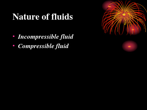
Nature of fluids
• Incompressible fluid • Compressible fluid
Pressure concept
• Isotropy • Scalar • Unit • reference
Fluid statics and its application
• The equation for hydrostatic equilibrium • applications
VELOCITY PROFILE IN LAMINAR FLOW
• The velocity distribution of fluid flowing in circular conduit and over a plane
• Average velocity • Maximum velocity • The relation between the average velocity
Turbulence can result from 1. contact of the flowing stream with solid
boundaries 2. contact between two layers of fluid moving
at different velocities.
The fluid moves erratically in form of crosscurrents and eddies.
流体力学与传热复习提纲
流体力学与传热复习提纲第一章 流体流动1) 压强的表示方法绝对压:以绝对真空为基准的真实压强值表压:以大气压为基准的相对压强值表绝=p p p a +如果绝对压小于表压,此时表压称为真空度。
例题 当地大气压为745mmHg 测得一容器内的绝对压强为350mmHg ,则真空度为 。
测得另一容器内的表压强为1360 mmHg ,则其绝对压强为 。
2) 牛顿粘度定律的表达式及适用条件dydu μτ= 适用条件:牛顿型流体 μ-流体粘度3) 粘度随温度的变化液体:温度上升,粘度下降;气体:变化趋势刚好和液体相反,温度上升,粘度增大。
4) 流体静力学基本方程式5) 流体静力学基本方程式的应用等压面及其条件静止、连续、同种流体、同一水平面6) 连续性方程对于稳定流动的流体,通过某一截面的质量流量为一常数:如果流动过程ρ不变,则1122u A u A =如果是圆管,则121222u d u d =因此管径增大一倍,则流速成平方的降低。
7) 伯努利方程式的表达式及其物理意义、单位不可压缩理想流体作稳定流动时的机械能衡算式∑-+++=+++21,222212112121f s W p u gz W p u gz ρρ 对于理想流动,阻力为0,机械能损失为0,且又没有外加功,则ρρ222212112121p u gz p u gz ++=++ )(2112z z g p p -+=ρ常数==uA m ρs物理意义:理想流体稳定流动时,其机械能守恒。
注意伯努利方程的几种表达形式和各物理量的单位。
例题 如题图所示虹吸装置。
忽略在管内流动损失,虹吸管出口与罐底部相平,则虹吸管出口处的流速8) 流型的判据流体有两种流型:层流,湍流。
层流:流体质点只作平行管轴的流动,质点之间无碰撞;湍流:流体质点除了沿管轴作主流运动外,在其它的方向上还作随机脉动,相互碰撞。
流型的判据: Re <2000,流体在管内层流,为层流区;Re >4000,流体在管内湍流,为湍流区;9) 流体在圆管内层流时的速度分布层流时流体在某一截面各点处的速度并不相等,在此截面上呈正态分布。
DESMI B114NPrimingPump操作与维护指南说明书

OPERATION AND MAINTENANCE INSTRUCTIONSDESMI priming pump B114NDESMI Pumping Technology A/STagholm 1 – DK-9400 Nørresundby – DenmarkTel.: +45 96 32 81 11Fax: +45 98 17 54 99E-mail: ***************Internet: Special pump no. ................._______________________________________________________________________________Table of Contents:1. PRODUCT DESCRIPTION (3)1.1DELIVERY (3)2. TECHNICAL DATA (3)2.1EXPLANATION OF THE NAME PLATE (3)2.2TECHNICAL DESCRIPTION (3)3. INSTALLATION (4)3.1WIRING (4)4. TRANSPORT/STORAGE (4)5. DISMANTLING (4)5.1ACCESS TO IMPELLER (4)5.2SHAFT SEAL (4)5.3INSPECTION (5)6. ASSEMBLING (5)6.1FITTING SHAFT AND SHAFT SEAL (5)6.2FITTING IMPELLER (5)6.3SHAFT (5)7. FROST PROTECTION (5)8. DISMANTLING (6)9. START-UP (6)9.1STARTING (6)10. INSPECTION AND MAINTENANCE (8)11. REPAIRS (8)11.1ORDERING SPARE PARTS (8)12. OPERATING DATA (8)13. EU DECLARATION OF CONFORMITY (9)14. INFORMATION RELEVANT FOR DISASSEMBLY OR DISPOSAL AT END-OF-LIFE (10)15. ASSEMBLY DRAWING B114N (11)14.1SPARE PARTS LIST B114N (11)16. DIMENSIONAL SKETCH (12)_____________________________________________________________________________________________________________________________________________________________DESMI Pumping Technology A/S 31. PRODUCT DESCRIPTIONThese maintenance and operation instructions apply to the DESMI priming pumps B114N. The pumps have 1/2" connections on suction and pressure side. B114N is a vacuum pump of the water ring type, with mechanical shaft seal, bronze shaft, impeller and pump casing.For special applications the pump can be delivered in other material combinations – e.g. with stainless steel shaft and ductile cast iron impeller and pump casing.Max. temperature for standard design is 80°C.The pumped liquid serves as lubricant for the pumps and therefore, they do not have to be lubricated further.Max. pump speed is 3600 RPM. The pump is driven by an electric motor, which may be a standard AC motor, or a DC motor.1.1 DELIVERY- Check on receipt that the delivery is complete and undamaged.- Defects and damages, if any, to be reported to the carrier and the supplier immediatelyin order that a claim can be advanced.2. TECHNICAL DATA2.1 EXPLANATION OF THE NAME PLATEThe pumps are equipped with a name plate indicating pump type, production week, production year, item list number if the pump has been sold alone, or an order number, if the pump has been sold when built together with another machine.Before putting a pump into operation, the suitability of the material combination of the pump must always be taken into consideration. In case of doubt, contact the supplier.If the pumps are intended for special purposes the following is to be indicated:Pump No. : _________________________________________________ Pump type : _________________________________________________ Application : _________________________________________________ Comment : _________________________________________________2.2 TECHNICAL DESCRIPTIONThe noise level indicated is the airborne noise including the motor. The noise depends on the motor type supplied, as the noise from the pump can be calculated as the noise level of the motor + 2dB(A). This noise level applies to pumps with electric motors.The permissible loads on the flanges on suction and pressure side are stated in the table below:______________________________________________________________________________ DESMI Pumping Technology A/S 4Fv : The max. permissible sum of the vertical forces on the two connections. Fh : The max. permissible sum of the horizontal forces on the two connections. ∑F : The vectorial sum of the two forces Fv and Fh.∑Mt : The max. permissible sum of torques on the two connections.In connection with the permissible loads on the connections stated in the above table the following is to be observed:222⎪⎪⎭⎫⎝⎛⎪⎭⎫⎝⎛∑∑+∑∑t M calc M F calc F where index "calc" is the values calculated by the user.3. INSTALLATIONThe max. permissible loads on the connections stated in paragraph 2.2 must be observed. At installations pumping hot or very cold liquids the operator must be awarethat it is dangerous to touch the pump surface and he is to take the necessary safety measures.3.1 WIRING Wiring to be carried out by authorized skilled workmen according to the rulesand regulations in force.4. TRANSPORT/STORAGEThe pump is to be stored in a dry area.5. DISMANTLINGThe numbers in brackets refer to the position numbers on the assembly drawing.5.1 ACCESS TO IMPELLERRemove Allen screws (12) and dismantle the end cover (3). Remove the pointed screw (7). The impeller (1) can now be pulled off and inspected.5.2 SHAFT SEALRemove key (11) from the shaft (4). Remove the copper pipes (16) and (27) connected to the pump casing. Remove set screws (14) and pull the pump casing free of the shaft (4) and the electric motor and the shaft seal is pulled off the shaft. Press the seat out from behind the pump casing.5.3 INSPECTIONAfter dismantling as described in 5.1, inspect the impeller, end cover and pump casing. Replace the parts, if wear or corrosion is established in areas to such an extent that the priming ability of the pump is considerably deteriorated, or the pump makes more noise than usual. Check the seat in the shaft seal for flatness and cracks. Check rubber parts for elasticity.6. ASSEMBLING6.1 FITTING SHAFT AND SHAFT SEALFit the shaft (4) on the motor shaft. The motor shaft must entirely bottom the hole in the shaft (4). Fit and tighten the pointed screws (6) (first the middle screw). Check that the wobble of the shaft, measured as far as possible from the motor, does not exceed 0.07 mm (70 m).Fit the sealing washer (9) in the pump casing. Fit the pump casing on the motor with screws and washers (14).Please note which type of rubber is used in the shaft seal bellows. As standard the material is nitrile, but it might be EPDM which will be damaged by mineral grease. Use soft soap or silicone grease for EPDM. Before fitting the seat, clean the recess in the cover. Dip the outer rubber ring of the seat in soapy water or grease it with silicone. Now press the seat into place with the fingers and check that all parts are correctly imbedded. If it is necessary to use fitting tools, then protect the sliding surface of the seat to prevent it from being scratched or cut. Lubricate the inner diameter of the rubber bellows on the slide ring with soapy water and push it over the shaft.Push the slide ring over the shaft with the hand. If the rubber bellows is tight, use a fitting tool and take care that the slide ring is not damaged. If the carbon ring is not fixed, it is important to check that it is fitted correctly, i.e. the chamfered/lapped side is to face the seat. The carbon ring can be held by a little grease. When using soapy water on the shaft, the bellows will settle and seat in about 15 minutes and until then tightness should not be expected. After start, check by viewing the leak hole that there are no leaks.6.2 FITTING IMPELLERFit the key (11) in the shaft and lead the impeller over the shaft. Use an air gap gauge to place the impeller 0.05 mm from the pump casing when tightening the pointed screw (7). Fit the end cover and O-ring (13) with Allen screws (12). Fit the copper pipes (16) and (27) connected to the pump casing.6.3 SHAFTWhen the pump has been assembled, check that the shaft rotates freely and without noise.7. FROST PROTECTIONPumps which are not in operation during frost periods are to be drained to avoid frost damage. Alternatively, it is possible to use anti-freeze liquids in normal constructions.______________________________________________________________________________ DESMI Pumping Technology A/S 5______________________________________________________________________________ DESMI Pumping Technology A/S 68. DISMANTLINGBefore dismantling the pump make sure that it has stopped. Empty the pump of liquid before it is dismantled from the piping system. If the pump has been pumping dangerous liquids you are to be aware of this and take the necessary safety measures.If the pump has been pumping hot liquids, take great care that it is drained before it is removed from the piping system.The priming pump is designed for mounting on non-selfpriming centrifugal pumps thusmaking the pump unit self-priming. NOTE : The priming system only works if the delivery pipe on the main pump is shut off, e.g. by means of a non-return valve !9. START-UPThe pump will not function until the feed water tank has been filled with liquid. The liquid also serves as coolant for the shaft seal. In order to protect the shaftseal the pump must not run dry.The priming pump is designed for mounting on non-selfpriming centrifugal pumps thusmaking the pump unit self-priming. NOTE : The priming system only works if the delivery pipe on the main pump is shut off, e.g. by means of a non-return valve!9.1 STARTINGBefore starting the pump check that- the shaft rotates freely without jarring sounds. - the feed water tank is filled with liquid.Start the pump for a moment to check the direction of rotation. If the direction is correct (i.e. in the direction of the arrow), the pump may be started. Should the pump not function as intended, please proceed according to the fault-finding list. Bear in mind, though, that the pump was carefully checked and tested at the factory and that the majority of faults stem from the piping system.______________________________________________________________________________ DESMI Pumping Technology A/S 7______________________________________________________________________________DESMI Pumping Technology A/S 810. INSPECTION AND MAINTENANCEInspect the shaft seal in B114N for leaks at regular intervals.- Before any inspection of a pump without guard check that the unit cannot be startedunintentionally.- The system is to be without pressure and drained of liquid.- The repairman must be familiar with the type of liquid which has been pumped as wellas the safety measures he is to take when handling the liquid.11. REPAIRS11.1 ORDERING SPARE PARTSWhen ordering spare parts please always state pump type and pump No. (indicated on the name plate of the pump). See also spare parts drawing with item No´s and part names. See assembly drawing.12. OPERATING DATAThe powers indicated in the table below constitute the max. power consumption of the pump. The following working pressures are allowed:13. EU DECLARATION OF CONFORMITYDESMI Pumping Technology A/S, hereby declare that our pumps of the type B114N are manufactured in conformity with the following essential safety and health requirements in the COUNCIL DIRECTIVE 2006/42/EC on machines, Annex 1.The following harmonized standards have been used:Pumps delivered by us connected with prime movers are CE-marked and comply with the above requirements.Pumps delivered by us without prime movers (as partly completed machinery) must only be used when the prime mover and the connection between prime mover and pump comply with the above requirements.Nørresundby, March 05 2019Henrik Mørkholt SørensenManaging DirectorDESMI A/STagholm 1, 9400 Nørresundby______________________________________________________________________________ DESMI Pumping Technology A/S 9______________________________________________________________________________ DESMI Pumping Technology A/S 1014. INFORMATION RELEVANT FOR DISASSEMBLY OR DISPOSAL AT END-OF-LIFENo damage materials are used in DESMI pumps – please refer to DESMI Green Passport (can be sent on request – contact a DESMI sales office) – i.e. common recycling companies can handle the disposal at end-of-life. Alternatively the pump and motor can be returned to DESMI at end-of-life for safe recycling.______________________________________________________________________________ DESMI Pumping Technology A/S 1115. ASSEMBLY DRAWING B114N14.1 SPARE PARTS LIST B114N1 Impeller 14 Set screw/washer 27 Copper pipe2 Pump casing 15 Angle nipple 28 Angle nipple3 End cover 16 Copper pipe 29 Fitting4 Shaft 17 Hexagon nipple 30 Magnetic valve *5 Shaft seal 18 Bushing 31 Pressure switch *6 Pointed screw 19 Filter32 Muff 7 Pointed screw 20 Hexagon nipple 33 Nipple 8 Feed water tank 21 Non-return valve 34 Muff-tee 9 Sealing washer 22 Pipe clamp 35 Motor10 Pipe plug 23 Muff-tee11 Key24 Hexagon nipple 12 Allen screw 25 Red. nozzle 13 O-ring 26Hexagon nipple*) OPTION16. DIMENSIONAL SKETCH______________________________________________________________________________ DESMI Pumping Technology A/S 12。
2020中国石油大学(华东)油气储运专业综合考研初试考试大纲
一、考试要求:1、要求考生掌握工程流体力学和传热学的基本概念、基本原理和基本计算分析方法,具有运用基础理论解决实际问题的能力。
2、考试时携带必要书写工具之外,须携带计算器。
二、考试内容:1、工程流体力学(1)流体及其主要物理性质a)正确理解和掌握流体及连续介质的概念;b)流体主要物理性质:密度、重度和相对密度的关系;流体压缩性、膨胀性及流体粘性产生原因及温度对流体粘性的影响;牛顿内摩擦定律;正确理解理想流体和实际流体的概念等;c)作用在流体上的力。
(2)流体静力学a)熟练掌握流体静压力的概念和二个基本特性;b)掌握用微元体分析法推导流体平衡微分方程的方法,熟练掌握水静力学基本方程式及应用;c)掌握压强表示方法(绝对压强、表压和真空度)、单位换算关系以及测量和计算;d)掌握绝对静止与相对静止流体中的等压面和压强分布规律的分析方法;e)掌握在液面压强p0=pa和p0≠pa两种情况下静止流体作用在平面和曲面上的总压力(包括大小、方向和作用点)以及物体浮力的计算方法。
(3)流体运动学与动力学基础a)正确理解描述流体运动的拉格朗日法、欧拉法,随体导数及其意义;b)掌握稳定流与不稳定流、流线与迹线、有效断面、流量、断面平均流速、流束与总流、空间和平面及一元流动、动能修正系数、缓变流、水头线(位置水头线线、测压管水头和总水头线)及水力坡降、流量系数、总压强与驻压强、泵的扬程和功率等基本概念;c)掌握欧拉运动方程、连续性方程、伯努利方程及动量方程的推导思路,并理解方程的物理意义及使用条件和范围,并熟练掌握连续性方程、伯努利方程和动量方程的应用。
(4)流体阻力和水头损失a)正确理解和掌握层流、紊流、雷诺数、水力半径、水力光滑与水力粗糙等概念;b)掌握因次分析和相似原理(特别是各种比尺及三个相似准数:雷诺数、富劳德数、欧拉数)在试验中的应用;c)掌握用N-S 方程分析几种典型的层流问题(如圆管层流、平板层流等)流动规律;d)掌握层流、紊流状态下圆管和非圆管的水头损失(沿程损失及局部损失)的计算方法。
流体力学与传热学-1

2、连续介质假设(1753年欧拉)
假定流体是由无穷多个、无穷小的、紧密毗邻、连续不断的流体质点所构 成的一种绝无间隙的连续介质。 流体状态的宏观物理量如速度、压强、密度、温度等都可以作为空间和 时间的连续函数
§1.4 流体的主要物理性质
1、流体的密度与重度
密度: 单位体积内流体的质量
lim
流体之间或流体与固体之间的相互作用力;
流动过程中动量、能量和质量的传输规律等。
2、流体力学的发展简况 1、经验阶段(十七世纪前)
大禹治水 4000多年前的大禹治水 古代已有大规模的治河工程。 (公元前256~210年) 秦代,修建了都江堰、郑国渠、灵渠三大水利工程对明槽水流和堰 流流动规律的认识已经达到相当水平。 (公元前156~前87) 西汉武帝时期,为引洛水灌溉农田,在黄土高原上修建了龙首渠 创造性地采用了井渠法,即用竖井沟通长十余里的穿山隧洞,有效地防 止了黄土的塌方。 真州船闸(960-1126) 北宋时期,在运河上修建的真州船闸与十四世纪末荷兰的同类船相 比,约早三百多年。
两层气体之间的黏性力主要由分子动量交换形成
一般仅随温度变化,液体温度升高黏度减小,气体温度升高黏度增大。
8) 黏性流体和理想流体
黏性流体 实际中的流体都具有粘性,因为都是由分子组成,都存在分子间的 引力和分子的热运动,故都具有黏性。 理想流体(假想没有黏性的流体) 一些情况下基本上符合粘性不大的实际流体的运动规律,可用来描 述实际流体的运动规律,如空气绕流圆柱体时,边界层以外的势流就可 以用理想流体的理论进行描述。 还由于一些黏性流体力学的问题往往是根据理想流体力学的理论进 行分析和研究的。 再者,在有些问题中流体的黏性显示不出来,如均匀流动、流体静 止状态,这时实际流体可以看成理想流体。
- 1、下载文档前请自行甄别文档内容的完整性,平台不提供额外的编辑、内容补充、找答案等附加服务。
- 2、"仅部分预览"的文档,不可在线预览部分如存在完整性等问题,可反馈申请退款(可完整预览的文档不适用该条件!)。
- 3、如文档侵犯您的权益,请联系客服反馈,我们会尽快为您处理(人工客服工作时间:9:00-18:30)。
• Select a pump with high efficiency contours over your range of expected operating points. A few points of efficiency improvement can save significant energy over the life of the pump.
The performance curve of centrifugal pump shows the pump’s capacity and total head. It also shows required power, and NPSH requirement over a range of flow rates.
Classification:
• fans for low pressures, discharge heads are
low, from about 0.1 m to 1.5 m H2O.
• blowers for intermediate pressures,
• compressors for high pressures
The increase in pressure, however, is the product of the developed head and the fluid density. If a pump develops, say, a head of 30.5m and is full of water, the increase in pressure is 2.95 atm.
Positive-displacement pumps are not subject to air binding.
2.2.7 pump selection
Before a centrifugal pump is selected, its application must be clearly understood. It is necessary to know the liquid to be handled, the total head, capacity and, in most cases, the temperature, viscosity, vapor pressure, and specific gravity.
2.3.1 Fans
The commonest method for moving small volumes of gas at low pressures is by means of a fan. Large fans are usually centrifugal and their operating principle is similar to that of centrifugal pumps.
It also shows the pump’s best efficiency point (BEP). The pump operates most cost effectively when the operating point is close to the BEP.
Pumps can generally be ordered with a variety of impeller sizes. Each impeller has a separate performance curve (see Figure ). To select a midrange impeller that can be trimmed or replaced to meet higher or lower flow rate requirements.
In chemical industry, the task of pumps election is frequently further complicated by the presence of solids in the liquid and liquid corrosion characteristics requiring special materials of construction.
2.2.6 Pump priming
If the impeller speed, the radius of the impeller, and the velocity of the fluid leaving the impeller are constant, the developed head is the same for fluids of all densities and is the same for liquids and gases
2.3 Gas-Moving Machinery
Gas-moving machinery comprises mechanical devices used for compressing and moving gases. They are often classified from the standpoint of the pressure heads produced
If the pump is full of air at ordinary density, the pressure increase is about 0.0035atm. It is called air bound and pump can accomplish nothing until the air has been replaced by a liquid.