龙威开关电源说明书
开关电源操作手册

开关电源操作手册因部分开关电源(爱默生、中达、中兴、北京动力源、托普)参数设置不准确和监控单元显示数值与实际情况有偏移等问题,使基站蓄电池长期处于过充、欠充、过放等情况,导致后备电源不足当市电中断后,频繁发生因电源问题产生的大面积断站等严重事故。
因以上述技术隐患问题,我部门针对现网基站开关电源设备参数设置按基站重要层次分为三种:传输节点(3个以上)、VIP、普通站。
参数设置如下:一、基本要求:1、蓄电池均/浮充电压请按现场蓄电池端电压采样为准。
2、蓄电池容量根据现场实际蓄电池容量设置。
3、根据交流供电环境决定周期均充时间设置,正常交流供电环境设置3个月或100天一次;市电停电频繁的基站均充设置40-60天一次。
二、具体要求:传输节点站:均充 28.2V浮充26.8V155/622传输备:一次下电:23V2.5G:一次下电:23.5V二次下电:21.6VVIP基站:均充 28.2V浮充26.8V155/622传输备:一次下电:23V2.5G:一次下电:23.5V二次下电:21.6V普通基站:均充 28.2V浮充26.8V一次下电:23V二次下电:21.6V注:普通站一二次下电请根据实际蓄电池情况作相应调整三、操作手册针对现网使用开关电源(爱默生、中达、中兴、北京动力源、托普)以中达MCS_3000为例:本系统监控单元采用全智能化设计,内装微处理器,全数字化指示与调整,监控系统输入输出,整流模块状态、电池及环境温度、充放电控制与异常状况的告警与指示。
备有RS-232接口,具有遥讯、遥测、遥控功能,符合无人值守与集中监控的需要。
外接PC机采用中文窗口环境操作,可配合打印机提供系统文字信息,亦具有传呼机告警功能,能将主要告警通知用户,使用户随时获得系统最新信息。
监控单元与整流模块间以信号线联机。
它收集由整流模块传来的告警信号及电流值。
并可对整流模块下达停机、浮充/均充控制及浮充电压温度补偿的电压修正指令,下图为水平式监控单元外观图。
Eaton Moeller MSC-D DOL开关机启动器说明书

Eaton 283166Eaton Moeller® series MSC-D DOL starter, 380 V 400 V 415 V: 4 kW, Ir= 6.3 - 10 A, 24 V DC, DCGeneral specificationsEaton Moeller® series MSC-D DOL starter2831664015082831660MSC-D-10-M9(24VDC)95 mm 180 mm 45 mm 0.645 kgUL File No.: E36332 CE VDE 0660CSA Class No.: 3211-24 UL Category Control No.: NLRV CSA File No.: 012528 CSA-C22.2 No. 60947-4-1-14 CSAIEC/EN 60947-4-1 ULUL 60947-4-1Product NameCatalog Number EANModel CodeProduct Length/Depth Product Height Product Width Product Weight CertificationsShort-circuit releaseTemperature compensated overload protection CLASS 10 AScrew terminalsNo1IP20NEMA OtherDirect starterDIN rail16.3 A10 AIII36000 V ACAlso motors with efficiency class IE3 Starter with Bi-Metal releaseDCFitted with: Functions ClassConnectionConnection to SmartWire-DTCoordination typeDegree of protectionModelMounting methodNumber of auxiliary contacts (normally closed contacts) Number of auxiliary contacts (normally open contacts) Overload release current setting - minOverload release current setting - maxOvervoltage categoryPollution degreeRated impulse withstand voltage (Uimp)Suitable forTypeVoltage typeMax. 2000 m -25 °C55 °C 8.5 A9 A2.2 kW4 kW230 - 415 V AC15 A, 600 V AC, (UL/CSA)1 A, 250 V DC, (UL/CSA)A600, AC operated (UL/CSA) P300, DC operated (UL/CSA)150 A 155 A 2.6 W 0 V0 V0 V0 V 24 V 24 VAltitudeAmbient operating temperature - min Ambient operating temperature - max Rated operational current (Ie)Rated operational current (Ie) at AC-3, 380 V, 400 V, 415 V Rated operational power at AC-3, 220/230 V, 50 HzRated operational power at AC-3, 380/400 V, 50 HzRated operational voltageSwitching capacity (auxiliary contacts, general use) Switching capacity (auxiliary contacts, pilot duty)Rated conditional short-circuit current (Iq), type 2, 380 V, 400 V, 415 VShort-circuit release (Irm) - max Power consumption (sealing) at DCRated control supply voltage (Us) at AC, 50 Hz - min Rated control supply voltage (Us) at AC, 50 Hz - max Rated control supply voltage (Us) at AC, 60 Hz - min Rated control supply voltage (Us) at AC, 60 Hz - max Rated control supply voltage (Us) at DC - minRated control supply voltage (Us) at DC - max9 W0 W3 W9 A2.6 WMeets the product standard's requirements.Meets the product standard's requirements.Meets the product standard's requirements.Meets the product standard's requirements.Meets the product standard's requirements.Does not apply, since the entire switchgear needs to be evaluated.Does not apply, since the entire switchgear needs to be evaluated.Meets the product standard's requirements.Does not apply, since the entire switchgear needs to be evaluated.Meets the product standard's requirements.Does not apply, since the entire switchgear needs to be evaluated.Motor Starters in System xStart - brochureSimple, flexible and safe! Distribution system for motor-starter combinationsSave time and space thanks to the new link module PKZM0-XDM32MEProduct Range Catalog Switching and protecting motorsDA-DC-00004878.pdfDA-DC-00004910.pdfeaton-manual-motor-starters-motorstarter-msc-d-dol-starter-dimensions.epseaton-manual-motor-starters-mounting-msc-d-dol-starter-3d-drawing.eps eaton-general-ie-ready-dilm-contactor-standards.epsETN.MSC-D-10-M9(24VDC).edzIL034038ZUIL034014ZUWIN-WIN with push-in technologyDA-CS-msc_d_bg1DA-CD-msc_d_bg1eaton-manual-motor-starters-device-msc-d-dol-starter-wiring-diagram.epsEquipment heat dissipation, current-dependent PvidHeat dissipation capacity PdissHeat dissipation per pole, current-dependent PvidRated operational current for specified heat dissipation (In) Static heat dissipation, non-current-dependent Pvs10.2.2 Corrosion resistance10.2.3.1 Verification of thermal stability of enclosures10.2.3.2 Verification of resistance of insulating materials to normal heat10.2.3.3 Resist. of insul. mat. to abnormal heat/fire by internal elect. effects10.2.4 Resistance to ultra-violet (UV) radiation10.2.5 Lifting10.2.6 Mechanical impact10.2.7 Inscriptions10.3 Degree of protection of assemblies10.4 Clearances and creepage distances10.5 Protection against electric shock10.6 Incorporation of switching devices and components BrochuresCatalogsDeclarations of conformity DrawingseCAD modelInstallation instructions Installation videosmCAD modelWiring diagramsEaton Corporation plc Eaton House30 Pembroke Road Dublin 4, Ireland © 2023 Eaton. All Rights Reserved. Eaton is a registered trademark.All other trademarks areproperty of their respectiveowners./socialmediaDoes not apply, since the entire switchgear needs to be evaluated.Is the panel builder's responsibility.Is the panel builder's responsibility.Is the panel builder's responsibility.Is the panel builder's responsibility.Is the panel builder's responsibility.The panel builder is responsible for the temperature rise calculation. Eaton will provide heat dissipation data for the devices.Is the panel builder's responsibility. The specifications for the switchgear must be observed.Is the panel builder's responsibility. The specifications for the switchgear must be observed.The device meets the requirements, provided the information in the instruction leaflet (IL) is observed.10.7 Internal electrical circuits and connections 10.8 Connections for external conductors 10.9.2 Power-frequency electric strength 10.9.3 Impulse withstand voltage 10.9.4 Testing of enclosures made of insulating material 10.10 Temperature rise10.11 Short-circuit rating10.12 Electromagnetic compatibility10.13 Mechanical function。
高压大电流降压型开关电源芯片说明书
4.2 引脚描述
引脚序号 引脚名称
1
ADJ
2
FB
3
OUT
4
HIN
5
SD
6
LIN
7
GND
8
LO
9
VCC
10
VS
11
HO
12
VB
13
VDD
14
VDD
15
CT
16
GND
I/O
I
I O I I
I
GND O
Power O O O
Power Power
I
GND
描述 输出电压调节端,内部误差放大器基准电压为 1.35V,外接两个分压 电阻对输出电压设定,输出电压 Vout=(1+R1/R2)*1.35V,R1 为 上拉到输出端的电阻,R2 为下拉到 GND 的电阻。 输出电压反馈输入端,输出 5V 场合,可以用内部二极管。 PWM 低压输出端,下拉电阻到地。 逻辑输入控制信号高电平有效,控制高端功率 MOS 管的导通与截止。 过流保护脚,高电平有效,关闭 HO、LO 输出。 逻辑输入控制信号低电平有效,控制低端功率 MOS 管的导通与截 止。 芯片的地端。
输出控制低端 MOS 功率管的导通与截止。 驱动电源输入端,电压范围 2.8V-20V。 高端悬浮地端。 输出控制高端 MOS 功率管的导通与截止。 高端悬浮电源。 PWM 控制部分电源,电压范围 3.5V-20V,跟 14 脚相连。 PWM 控制部分电源,电压范围 3.5V-20V。 外接电容,设置振荡器工作频率范围 10KHz-100KHz,频率 f=(37.5 x10⁶ )/CT (单位为 pF)。 芯片的地端。
Siglent SPS5000X 系列宽范围可编程直流开关电源用户手册说明书
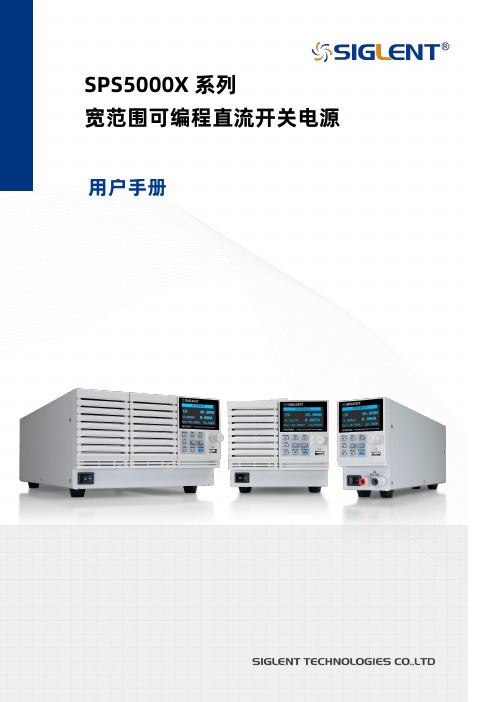
SPS5000X系列宽范围可编程直流开关电源用户手册目录1 引言 (4)2 安全要求 (5)2.1 一般安全概要 (5)2.2 安全符号和术语 (6)2.3 工作环境 (7)2.4 冷却要求 (7)2.5 AC电源供应 (8)2.6 清洁 (9)2.7 异常情况 (9)3 交付电源 (10)3.1 一般性检查 (10)3.2 质保 (10)3.3 维护协议 (11)4 SPS5000X可编程直流开关电源简介 (12)4.1 特性与特点 (13)4.2 型号介绍 (14)5 快速入门 (17)5.1 前面板 (17)5.2 后面板 (19)6 功能原理简介 (22)6.1 工作区 (22)6.2 CV和CC模式 (22)6.3 斜率 (23)6.4 泄放控制 (23)6.5 输出内阻 (24)6.6 保护报警 (25)6.7 注意事项 (25)6.7.1 浪涌电流 (26)6.7.2 峰值或峰值负载 (26)6.7.3 反向电流再生负载 (26)6.7.4 反向电流连接方法 (26)6.7.5 接地 (27)7 开关机和输出端口 (29)7.1 连接电源线 (29)7.2 开机 (29)7.3 关机 (30)7.4 输出端口 (30)8用户界面 (32)9 控制面板操作 (37)9.1 系统设置 (37)9.1.1 查看版本信息 (37)9.1.2 系统升级 (37)9.1.3 恢复默认 (37)9.1.4 蜂鸣器设置 (38)9.1.5 主机/从属机设置 (38)9.2 功能设置 (51)9.2.1 List功能 (51)9.2.2 OVP/OCP保护 (56)9.2.3 泄放控制 (56)9.2.4 CC/CV优先 (56)9.2.5 开启/关闭输出延时 (57)9.2.6 内阻设置 (57)9.2.7 测量平均值设置 (58)9.2.8 外部模拟量控制 (58)9.2.9 外部控制输出/关闭 (59)9.2.10 多通道设置 (60)9.2.11 模拟接口 (62)9.3 通讯接口设置 (65)9.3.1 USB (65)9.3.2 GPIB设置 (65)9.3.3 LAN设置 (65)10 远程控制 (66)10.1 控制方式 (66)10.2 语法惯例 (67)10.3 命令概要 (67)10.4 命令说明 (68)10.4.1 IEEE公用命令子系统 (68)10.4.2 Measure命令子系统 (71)10.4.3 Configure配置命令子系统 (74)10.4.4 List配置命令子系统 (84)10.4.5 系统配置命令子系统 (91)10.5 Web功能 (96)11 故障处理 (101)12 联系我们 (102)1 引言本用户手册包括与SPS5000X系列电源有关的重要的安全和安装信息,并包括电源的基本操作使用的简单操作教程。
开关电源规格书word资料16页
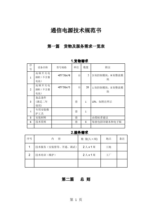
通信电源技术规范书第一篇货物及服务需求一览表第二篇总则1.总则说明与评价准则1.1 投标者应仔细阅读招标者发出的招标书中规定的所有条款,包括各项技术规格。
1.2 投标者提供的产品技术规格应与招标书中提出的要求一致。
投标者也可推荐出与招标书中规定的规格相类似的定型产品,但必须提供详细的技术规格偏差表。
1.3 投标者可推荐应用最新技术制造的产品,但其规格应相当或超过招标书中陈述的技术规格。
这种产品的性能、可靠性与耐久性必须有显著的提高,并在投标书中就选择该产品的意图提供详尽的证明文件及解释。
1.4 招标采购的设备应设计先进,采用经过验证的新工艺、新技术,并已有供货历史。
投标者应提供设备供应商(厂家)在生产该设备中经验方面的资料。
★1.5 对于招标书中提出的所有项目,投标者应表明在最近三年中所生产设备的编号(应与招标书提出的设备类型一致或非常相近),并附有主要用户名单以作参考。
投标商所供系统设备(应与招标书提出的设备类型一致或非常相近)在近3年中,铁路干线合同应累计500km以上。
1.6 评标及对中标者的选择都应以每个项目的总价格为基础,包括给予整个项目的折扣(如果有的话)。
然而,投标者应在投标价格表中列出每一分项目的单价与总价以及整套设备的总价,如果某个项目的总价出现错误,则以所报单价为依据,由买方重新评估总价。
1.7 根据招标者的意见,假如以合理价格对整套设备投标不能接受时,招标者有保留继续估价的权利,可以从原有整套项目中删去一项或几项,或从原有分项目中删去一个或几个部分,或单项估价。
2.技术规范总则2.1 除非在技术规范中另作规定,所有的设备和仪器的工作电源均采用单相交流220V(±10%)、50Hz(±1)。
设备应能在室外环境温度为-8~+45℃或者室内环境温度为+5~+40℃、相对湿度为90%(在+25℃时)、海拔高度在1000m 的条件下,连续运行24小时以上。
如果产品不能满足这些要求,投标者应申报偏差值。
DUM227 4850系列智能开关电源系统
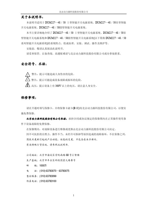
关于本说明书:本说明书适用于DUM227—48/50 Ⅰ型智能开关电源系统、DUM227—48/50Ⅱ型智能开关电源系统、DUM227—48/50Ⅲ型智能开关电源系统。
本书主要详细地介绍了DUM227—48/50 Ⅰ型智能开关电源系统、DUM227—48/50Ⅱ型智能开关电源系统和DUM227—48/50Ⅲ型智能开关电源系统(以下简称DUM227—48/50系列智能开关电源系统)的系统特点、组成原理、安装、调试、操作及维护等。
安装前,敬请认真阅读此说明书。
请妥善保管,以备查阅,尚遇疑难请与北京动力源科技股份有限公司或办事处联系。
安全符号、术语:警告:提示可能造成人身伤害的危险。
警告:提示可能造成设备故障或损坏的危险。
高压:提示设备上有300V 以上的电压,请注意人身安全。
保修事项:请在开通时填写保修卡,并将保修卡副卡(B 联)寄北京动力源科技股份有限公司,以便实施免费保修。
北京动力源科技股份有限公司承诺:承担合同或协议规定的保修期内在正常操作使用条件下设备故障的免费保修。
在保修期内,对故障设备进行维修或更换由北京动力源科技股份有限公司决定。
因不可抗拒的自然力、操作不当、未经许可拆卸等原因造成的故障损坏,不在保修之列。
因技术更新引起的产品功能、性能的变更,不包含在本手册内。
有关特殊订货系统,请参照此说明书。
公司地址:北京市海淀区学院南路68号汇智楼 生产基地;北京市丰台区科技园星火路8号 邮 编;10007l电 话:(010)63783070~63783075 售后服务:(010)63783099 传真电话:(010)63783100目录第一章概述 (1)一、简介 (1)二、系统特点 (1)三、使用环境与工作条件 (2)四、安全 (2)第二章电源系统 (3)一、主要技术指标 (3)二、基本工作原理 (3)三、系统组成 (3)第三章控制系统 (6)第四章整流器 (8)一、整流器工作原理 (8)二、整流器技术指标 (8)三、整流器外形 (10)第五章交直流配电 (11)一、交流配电 (11)二、直流配电 (13)第六章安装 (16)第七章操作 (19)第一章概述一、简介DUM227—48/50系列智能开关电源系统是北京动力源科技股份有限公司根据信息产业部行业标准,结合国内供电状况和使用要求,采用新型元器件设计、生产的高新技术产品。
开关电源说明书
1、开关电源的功能组成:(1)开关管的驱动电路(UC3844及其外围电路)(2)反馈电路(TL431和光耦PC817)(3)反激式变压器设计2、设计目标●输入:DC 200~500V。
●电源输出:+24V、50mA 供电给继电器15V、450mA 运放、传感器加7805+8V、1A CPU/DSP、逻辑电路(作反馈)25V、150mA 六路驱动20V 50mA 3844供电(开关电源自启动电源) 共计11路输出3、各功能部分原理(1)驱动电路部分驱动芯片使用UC3844或UC3845,引脚功能如下:引脚1、2是运算放大器输入端。
此设计中,光耦的输出直接接UC3844的误差放大器的脚1,而反向输入端脚2直接接地。
输出电压反馈直接联接到脚1,而不是脚2,略过了UC3844的内部误差放大器,这使得电源的动态响应更快。
引脚3是限流保护引脚。
当引脚电压超过1V时,PWM输出立即被封锁。
此处设置变压器原边流不得超过1.5A(变压器峰值电流为1.6A),由R=U/I得,R187=0.7欧。
另外在引脚3加470pf电容滤波。
R4、C5构成低通滤波器,将采到的电流信号滤波后供给3脚,提供电流反馈。
引脚4振荡频率设定端。
开关管的工作频率为40KHz.由于UC3844内部有个分频器,所以驱动MOSFET功率开关管的方波频率为芯片内部振荡频率的一半,则引脚4应设置为80KHz(UC3844最大振荡频率可为1MHz),根据计算估计公式f=1.7/RC,取R=91K,C=150PF(频率不一定设的很准,可以改变电阻值测定)。
引脚5为模拟地,引脚8是基准电压5V输出端。
引脚7是电源供电端,需15-20V。
引脚6是PWM输出端。
经一个限流电阻(100欧/0.25W)限流后驱动功IGBT,为保护功率IGBT,在脚6并联一支15V的稳压二极管。
(2)自启动电路开关电源只有交流侧供电,必须能够实现自动启动。
本设计的自启动电路如下图框内所示,基本原理是:启动过程,供电电压310V通过RR3、RR4给C125充电,当电压值达到15伏,驱动芯片UC3844开始工作,开关管正常驱动,直到变压器输出侧34输出电压稳定在20伏,整个电路系统工作,电源实现了自启动。
GEI1-5K逆变电源说明书A4版
目录前言第一篇GEI─05K/1K/2K/3K使用说明书一、简介1.1主要特点---------------------------------------------------------11.2注意事项 --------------------------------------------------------11.3系统概述 --------------------------------------------------------21.4系统框图---------------------------------------------------------21.5原理描述---------------------------------------------------------3二、安全使用2.1敬告用户---------------------------------------------------------42.2执行标准---------------------------------------------------------4三、外观3.1外型结构与功能说明-----------------------------------------------53.2前面板示意图-----------------------------------------------------63.3后面板示意图-----------------------------------------------------7四、安装4.1拆包与检验------------------------------------------------------ 84.2安装开孔尺寸-----------------------------------------------------84.3放置要求---------------------------------------------------------8五、接线及操作程序5.1接线-------------------------------------------------------------95.2开机前准备-------------------------------------------------------105.3设备操作程序-----------------------------------------------------10六、状态输出及保护报警6.1状态输出(选配件)-----------------------------------------------116.2保护功能---------------------------------------------------------116.3过载及故障告警---------------------------------------------------11七、订货须知--------------------------------------------------------12八、服务保证--------------------------------------------------------12九、技术性能指标---------------------------------------------------13目录第二篇GEI─5K使用说明书一、简介1.1主要特点---------------------------------------------------------141.2注意事项 --------------------------------------------------------141.3系统框图及描述 --------------------------------------------------15二、外型结构及功能说明2.1电源设备立体示意图-----------------------------------------------162.2前面板示意图及功能说明-------------------------------------------172.3后面板示意图及功能说明-------------------------------------------192.4 GEI-5K卧式机箱开孔示意图----------------------------------------21三、安装及接线方法3.1安装注意事项-----------------------------------------------------213.2 GEI-5K卧式机箱接线方法------------------------------------------223.3 GEI-5K立式机箱接线方法------------------------------------------23四、操作程序4.1开机前准备-------------------------------------------------------244.2第一次开机操作程序-----------------------------------------------244.3日常开关机操作程序-----------------------------------------------26五、状况处理5.1符号代表意义如下-------------------------------------------------265.2设备运转状况显示及不正常时之处理方式-----------------------------26六、通讯界面说明--------------------------------------------------34七、订货须知-------------------------------------------------------35八、服务保证-------------------------------------------------------35九、技术指标-------------------------------------------------------36前言衷心感谢您选用我公司所生产的电源产品,希望我们的产品能使您满意。
威小龙电源用户手册说明书
Page 1©1998 Whelen Engineering Company Inc.Form No.13366A (020900)For warranty information regarding this product, visit /warranty•Proper installation of this product requires the installer to have a good understanding of automotive electronics, systems and procedures.•Whelen Engineering requires the use of waterproof butt splices and/or connectors if that connector could be exposed to moisture.•Any holes, either created or utilized by this product, should be made both air- and watertight using a sealant recommended by your vehicle manufacturer.•Failure to use specified installation parts and/or hardware will void the product warranty.•If mounting this product requires drilling holes, the installer MUST be sure that no vehicle components or other vital parts could be damaged by the drilling process. Check both sides of the mounting surface before drilling begins. Also de-burr the holes and remove any metal shards or remnants. Install grommets into all wire passage holes.•If this manual states that this product may be mounted with suction cups, magnets, tape or Velcro®, clean the mounting surface with a 50/50 mix of isopropyl alcohol and water and dry thoroughly.•Do not install this product or route any wires in the deployment area of your air bag. Equipment mounted or located in the air bag deployment area will damage or reduce the effectiveness of the air bag, or become a projectile that could cause serious personal injury or death. Refer to your vehicle owner’s manual for the air bag deployment area. The User/Installer assumes full responsibility to determine proper mounting location, based on providing ultimate safety to all passengers inside the vehicle.•For this product to operate at optimum efficiency, a good electrical connection to chassis ground must be made. The recommendedprocedure requires the product ground wire to be connected directly to the NEGATIVE (-) battery post (this does not include products that use cigar power cords).•Do not attempt to activate or control this device in a hazardous driving situation.•Use only soap and water to clean the outer lens. Use of other chemicals could result in premature lens cracking (crazing) and discoloration. Lenses in this condition have significantly reduced effectiveness and should be replaced immediately. Inspect and operate this product regularly to confirm its proper operation and mounting condition. Do not use a pressure washer to clean this product.•It is recommended that these instructions be stored in a safe place and referred to when performing maintenance and/or reinstallation of this product.•FAILURE TO FOLLOW THESE SAFETY PRECAUTIONS AND INSTRUCTIONS COULD RESULT IN DAMAGE TO THE PRODUCT OR VEHICLE AND/OR SERIOUS INJURY TO YOU AND YOUR PASSENGERS!A u t o m o t i v e : Warnings to InstallersWhelen’s emergency vehicle warning devices must be properly mounted and wired in order to be effective and safe. Read and follow all of Whelen’s written instructions when installing or using this device. Emergency vehicles are often operated under high speed stressful conditions which must be accounted for when installing all emergency warning devices. Controls should be placed within convenient reach of the operator so that they can operate the system without taking their eyes off the roadway. Emergency warning devices can require high electrical voltages and/or currents. Properly protect and use caution around live electrical connections.Grounding or shorting of electrical connections can cause high current arcing, which can cause personal injury and/or vehicle damage, including fire. Many electronic devices used in emergency vehicles can create or be affected by electromagnetic interference. Therefore, after installation of any electronic device it is necessary to test all electronic equipment simultaneously to insure that they operate free of interference from other components within the vehicle. Never power emergency warning equipment from the same circuit or share the same grounding circuit with radio communication equipment. All devices should be mounted in accordance with the manufacturer’s instructions and securely fastened to vehicle elements of sufficient strength to withstand the forces applied to the device. Driver and/or passenger air bags (SRS) will affect the way equipment should be mounted. This device should be mounted by permanent installation and within the zones specified by the vehicle manufacturer, if any. Any device mounted in the deployment area of an air bag will damage or reduce the effectiveness of the air bag and may damage or dislodge the device. Installer must be sure that this device, its mounting hardware and electrical supply wiring does not interfere with the air bag or the SRS wiring or sensors. Mounting the unit inside the vehicle by a method other than permanent installation is not recommended as unit may become dislodged during swerving; sudden braking or collision. Failure to follow instructions can result in personal injury. Whelen assumes no liability for any loss resulting from the use of this warning device. PROPER INSTALLATION COMBINED WITH OPERATOR TRAINING IN THE PROPER USE OF EMERGENCY WARNING DEVICES IS ESSENTIAL TO INSURE THE SAFETY OF EMERGENCY PERSONNEL AND THE PUBLIC.Warnings to UsersWhelen’s emergency vehicle warning devices are intended to alert other operators and pedestrians to the presence and operation of emergency vehicles and personnel. However, the use of this or any other Whelen emergency warning device does not guarantee that you will have the right-of-way or that other drivers and pedestrians will properly heed an emergency warning signal. Never assume you have the right-of-way. It is your responsibility to proceed safely before entering an intersection, driving against traffic, responding at a high rate of speed, or walking on or around traffic lanes. Emergency vehicle warning devices should be tested on a daily basis to ensure that they operate properly. When in actual use, the operator must ensure that both visual and audible warnings are not blocked by vehicle components (i.e.: open trunks or compartment doors), people, vehicles, or other obstructions. It is the user’s responsibility to understand and obey all laws regarding emergency warning devices. The user should be familiar with all applicable laws and regulations prior to the use of any emergency vehicle warning device. Whelen’s audible warning devices are designed to project sound in a forward direction away from the vehicle occupants. However, because sustained periodic exposure to loud sounds can cause hearing loss, all audible warning devices should be installed and operated in accordance with the standards established by the National Fire Protection Association.Safety FirstThis document provides all the necessary information to allow your Whelen product to be properly and safely installed. Before beginning the installation and/or operation of your new product, the installation technician and operator must read this manual completely. Important information is contained herein that could prevent serious injury or damage.WARNING: This product can expose you to chemicals including Lead which is known to the State of California to cause cancer and birth defects or other reproductive harm. For more information go to .Installation Guide:Intelligent Strobe Power SupplyModel ISP1882451 Winthrop RoadChester, Connecticut 06412-0684Phone: (860) 526-9504Internet: Salese-mail:*******************CustomerServicee-mail:*******************®ENGINEERING COMPANY INC.This ISP18824 Intelligent Strobe Power Supply can be installed in many different types of vehicles. The guidelines for the installation of this prod-uct are written so that no matter what vehicle is being used, the installation will be simple and straight forward.Selecting a Mounting Location:The logical choice for a mounting area would be a trunk or similar com-partment. However, due to the wide variety of vehicles onto which the ISP18824 can be installed, this is not always possible. The following guidelines will help the installer select an alternative:A)The unit should be mounted on a metal surface to aid heat dissipa-tion. Be sure that this surface is not one that either generates or is exposed to excessive heat during normal operation of the vehicle. B)Do not select a location where the power supply will be exposed topotential damage from any unsecured or loose equipment.C)Be sure the area selected will not be exposed to water.D)When routing the wires, it is important to choose a path that will keepthe wires away from excessive heat or vehicle equipment that could compromise the integrity of the wires (ex. trunk lids, door jams, etc.).E)Be sure your mounting location does not block the cooling fan in therear of the unit. (See last page)WARNING! When extending the communication wires (BLUE & GREY), use either the Whelen 25ft cable (P/N 46-9641638-250) or similar “twisted pair” wires.WARNING! All customer supplied wires that connect to the positive terminal of the battery must be sized to supply at least 125% of the maximum operating current and FUSED at the battery to carry that load. DO NOT USE CIRCUIT BREAKERS WITH THIS PRODUCT! Caution: Permanent mounting of this product will requiredrilling. It is absolutely necessary to make sure that no other vehicle components could be damaged by this process. Check both sides of the mounting surface before starting. If damage is likely, select a dif-ferent mounting location.Operating Instructions:The ISP18824 has been designed to emulate the operations of four exist-ing Whelen power supplies:The UPS-188C / Alternating Pairs..................................ALT 2X2X4The DOT-188C / Simultaneous Pairs........................SIMUL. 2X2X4The DOT-188MN / Simultaneous...............................SIMUL. 2X2X4The BL188C............................................................................ B-LINK Select the desired operational mode by configuring dip switches #1, 2 3 & 8, located on the front panel of the power supply. The use of Dip Switches #4 & 5 is explained in the “Hi-Lo Power” section. The following section will explain how to place the ISP18824 into each of these respective modes, as well as outline the operational procedures for each mode.Section 1: Emulation Modes:Applying +24VDC to the control wires indicated in each mode (using cus-tomer supplied switches) will cause the results indicated. For a listing of the available flash patterns refer to Section 2: Flash Patterns.ALT. 2X2X4 Mode / Default Configuration:Dip SwitchesThe dip switch configuration for UPS188C-mode is:Switch 1 - OFF Switch 2 - OFF Switch 3 - OFF Switch 8 - OFF Control WiresWire #1 = Outlets 1 & 2 Enabled Wire #2 = Outlets 3 & 4 EnabledWire #3 = 5, 6, 7 & 8 EnabledSIM 2X2X4 Mode:Dip SwitchesThe dip switch configuration for DOT-188C mode is:Switch 1 - ON Switch 2 - OFF Switch 3 - OFF Switch 8 - OFF Control WiresWire #1 = Outlets 1 & 3 Enabled Wire #2 = Outlets 5 & 7 EnabledWire #3 = 2, 4, 6 & 8 Enabled SIM 2X2X4MN Mode:Dip SwitchesThe dip switch configuration for DOT188MN Mode:Dip Switch 1 - OFF Dip Switch 3 - OFFDip Switch 2 - ON Dip Switch 8 - OFFControl WiresControl Wire #1 = Outlets 2 & 4 EnabledControl Wire #2 = Outlets 6 & 8 EnabledControl Wire #3 = Outlets 1, 3, 5 & 7 EnabledALT 2X2X2X2 Mode:Dip SwitchesThe dip switch configuration for ALT 2X2X2X2 Mode:Dip Switch 1 - ON Dip Switch 3 - OFFDip Switch 2 - ON Dip Switch 8 - OFFBL188C Mode:When the ISP18824 is configured to emulate the BL188C, it is important to understand that the connections and operational procedures used are different from any of the other modes.Dip SwitchesBL188C emulation is accomplished by placing Dip Switch 8 in the ON position. At this point, the remaining Dip Switches (1 thru 3) are used to configure the address of the ISP18824 for use in a B-LINK system. The addressing properties function as follows:To Configure Address 1:To Configure Address 2:Dip Switch 1 - ON Dip Switch 1 - OFFDip Switch 2 - OFF Dip Switch 2 - ONDip Switch 3 - OFF Dip Switch 3 - OFFTo Configure Address 3Dip Switch 1 - OFF Dip Switch 2 - OFF Dip Switch 3 - ON Control WiresIn this configuration, control wires 1, 2, 3 & 4 are not used to enable out-lets or control Hi/Lo power activation, as with the previous modes. Outlet control and Hi/Lo power activation is handled by the B-LINK Multi-Purpose Controller.Section 2: Flash PatternsThe ISP18824 can generate any of 16 available flash patterns simply acti-vating the 4 Pattern Control wires, either individually or in combination. Table 1 on Page 3 outlines all of the available patterns and the wire activa-tions needed to produce them.Section 3: Hi/Lo PowerHi/Lo power activation and functionality can be configured in any of 4 modes, depending upon how Dip Switches 4 & 5 are positioned. Table 2 on Page 3 outlines each of the 4 configurations and their attributes. NOTE: In BL188C emulation mode, Hi/Lo power activation is controlled with a B-LINK Multi-Purpose Controller.Section 4: Diagnostix™ / OptionalThe optional Diagnostix™ display allows the operator to confirm proper operation of not only the 8 outlets on the ISP18824, but of the strobe light and strobe cable connected to these outlets as well. Each LED indicator on the Diagnostix™ display, provides diagnostic information for one outlet. For example; LED #1 monitors Outlet #1, etc. The LED’s appearance indi-cates the condition of it’s corresponding outlet. Refer to Table 3 on Page 3. Section 5: PhasingWhen you turn dip switch 7 on, you will cause outlets 1-4 to drift slowly in and out of sync with outlets 5-8. Lights will work as described in each mode. The result will be a more eye catching or random flash pattern. IMPORTANT! It is the responsibility of the installation technician to make sure that the installation and operation of this product will not interfere with or compromise the operation or efficiency of any vehicle equipment!Page 2Page 3Page 4ISP18824REPLACEMENT PARTSLEFT SWEEP 76543218RIGHT SWEEP 12345678SPLIT-SWEEP 32112344LEFTRIGHTLamp 1Lamp 2Lamp 3Lamp 4Lamp 5Lamp 6Outlet 1Outlet 5Outlet 3Outlet 7Outlet 2Outlet 6Lamp 7Lamp 8Outlet 4Outlet 8TRAFFIC ADVISORIn order for the Traffic Advisor patterns to flash properly,it is necessary for the lamps to be connected to theISP18824in the following pattern.The Traffic Advisor (or T/A)mode is comprised of four,traffic control-oriented flash patterns.Traffic Advisor Mode...Control Wire #1=LEFT SWEEP Control Wire #2=RIGHT SWEEPControl Wire #3=ALTERNATING FLASH Control Wire #2=SPLIT SWEEPDip SwitchesControl WiresThe dip switch configuration for Traffic Advisor Mode:Dip Switch 1-ON Dip Switch 2-ON Dip Switch 3-ON In this configuration,applying +24VDC to the control wires (using customer supplied switches)will have the following results:21ALTERNATING FLASH 12The T/A pattern mode is enabled as indicated in table 2.54WHEN MOUNTING UNIT KEEP REAR SIDE CLEAR OF OBSTRUCTIONS.8A IRF LO W72391ISP18824PARTS LIST01-0683157-00ISP18824STROBE POWER SUPPLY01-0662830-00123ISP18824FINAL ASSEMBLY CONTROL CONNECTOR ASSEMBLY 46-0725613-00446-0725945-00PATTERN CONNECTOR ASSEMBLY 2POS PHOENIX CONNECTOR 39CIJ02523-IJ 5CABLE ASSY,8POS TELEPHONE 8’02-0241485-08601-0267643-00702-0241485-25CABLE ASSY,8POS TELEPHONE 25'846-0725612-00POWER CONNECTOR ASSEMBLY 9DOT DIAGNOSTIC INDICATOR ASSEMBLY 25'TWISTED PAIR B-LINK CABLE 46-9641638250REF UPS DIAGNOSTIC INDICATOR ASSEMBLY 01-0267265-00ITEM PART NUMBER DESCRIPTIONN0.8X 5/8PAN HEAD SHEET METAL SCREWS(QUANTITY 4)T O P VIEW9.148.562When mounting this unit keep the rear side clear of obstructions.AIR FLOW8.635.001.81When mounting this unit vertically air must flow up.,5。
Eaton Pow-R-Line 4RX 电源板补充式说明书
SIGNIFICANT SAVINGS AND MAXIMUM FLEXIBILITYCustomers need to upgrade their existing electrical systems to meet growing power demands. Upgrading existing distribution equipment can present many challenges for facility managers such as high cost and a long shutdown. Eaton offers the most economical life extension solution with the new Pow-R-Line 4RX Panelboard, specifically designed to reduce installation time.Eaton retrofit solutions expand from lighting panelboards (Pow-R-Line 1RX & 2RX) to power panelboards, with the addition of the Pow-R-Line4RX retrofit. Panelboard chassis are engineeredto adapt to the existing enclosures and therefore significantly reduce the installation cost of an otherwise brand-new panelboard.The retrofit panelboard is available up to 1200A and is offered as an Eaton installed solution with EESS (Eaton Electrical Services and Systems).Benefits• Eaton’s installed solution• Reduced installation time• Site Verification andApplication Review• Extended warranty• CSA listed equipmentto fit into anymanufacturer's enclosureRetrofit Features• Panelboard andswitchboard retrofit• Integral depth adjustmentto fit custom depths• Custom trim collar• Tin plated aluminum andsilver-plated copper bus• Top and bottom entry orcross-bussed• Custom height• Surge protective devices• Metering options• Optional door overdistributionMarket Segment &Applications• Schools and Universities• Healthcare facilities• Commercial buildings• Industrial facilities• Utility installations• Hi-rise towers andcondominiumsBreaker Options• Padlock Hasp• Visible windows• Electronic trip units• Maintenance Mode (ARMS)• Communications overnetwork• Shunt trip• Auxiliary contacts• Bell alarm• Main or branch breakerup to 1200A• Higher interruptingcapacitiesAdvanced Retrofit Solutions• Distribution chassis retrofits in existing switchboards, including upgrade and refurbishment of existing bus systems, large frame breakers, metering, relays are available from EESS.2EATON Life Extension Solutions Pow-R-Line 4RX Retrofit PanelboardRequired Information• Dimensions (height, width, depth)• Short circuit rating • Top or bottom entry • Special neutral requirements • Location of existing lugs • Main breaker or main lug• Cross bus location (switchboard only) • Metering and SPD devices•Special door and trim requirements, if applicablePRL 4RX Interior reduces installation time by using an existingenclosure with adjustable sliding mechanismRetrofit Installation: Before & AfterN.B. Non-CSA Compliant retrofits can be accommodated by on-site special inspections by applicable Utility Authority, organized by EESSDimensional Guidelines (for compliance with CSA)Bus Amps (A)Interrupting Rating (kA)Max Branch Breaker (A)Voltage (Vac)Min Height (Inch)Min Width (Inch)120065120060073.544.012006560060073.538.08006560060057.030.08005040060057.024.0Depth RequirementsMin Depth (Inch)Notes11.5No collar 9Box collar < 9Custom collar Height RequirementsChassis SizeMin Height (Inch)26X 5738X 7250X88PRL4RX retrofit panels require special information that Eaton requires to pre-engineer this custom-made product, ensur-ing the retrofit will install in the space available. This information will also be used to highlight custom requirements, or any special issues. Please include the following details in the Tender Documents.Panel Designation:Exterior Photo and Interior Photo: Under separate coverWidth (W): Height (H): Depth(D):Flange (F) Dimensions:System information:System voltage: # Phases/ # Wires:Bus Amperage:Interrupting Capacity:Chassis Bus and Breaker Details:Main Breaker Amperage:Main Breaker incoming cable size and quantity:or Main Lug Only size and quantity:Copper silver plated or Aluminum tin plated Bus:Special Neutral requirements:How many neutrals:Panel Mounting Details:Surface or Flush Mounted:Special overhang of Flush trim, if required:Door Requirements, if any:Top or Bottom cable entry:Paint Colour Details:ASA 61 Gray, standardor, Special Colour:Additional Details:Panel Schedule: Sketch of Panel Layout showing Branch Breakers and Locations. See page 4.Special devices such as SPD, Metering:Other special requirements:Comments for PRL4RX RFQ specification:For Retrofit Installation, Eaton recommends the following comments be included in the T ender Documents:- Installation will be provided by Eaton Electrical Services and Systems personnel- C ontractor/ Owner is responsible to remove existing panel interior and trim assembly, to push existing cables aside,then re-install cables after the new PRL4RX retrofit is installed.3EATON Life Extension Solutions Pow-R-Line 4RX Retrofit PanelboardEaton is a registered trademark.All other trademarks are property of their respective owners.Eaton5050 Mainway Burlington ON 1-800-268-3578 EatonCanada.ca© 2021 Eaton Corporation All Rights Reserved Printed in CanadaPublication No. SA014046EN June 2021Notes:Follow us on social media to get the latest product and support information.。
- 1、下载文档前请自行甄别文档内容的完整性,平台不提供额外的编辑、内容补充、找答案等附加服务。
- 2、"仅部分预览"的文档,不可在线预览部分如存在完整性等问题,可反馈申请退款(可完整预览的文档不适用该条件!)。
- 3、如文档侵犯您的权益,请联系客服反馈,我们会尽快为您处理(人工客服工作时间:9:00-18:30)。
参数型号LW-1550KD 0-15V连续可调0-50A连续可调LED数字显示±1% ±1个字LW-1560KD 0-15V连续可调0-60A连续可调LED数字显示±1% ±1个字LW-3040KD0-30V连续可调0-40A连续可调LED数字显示±1% ±1个字LW-3050KD 0-30V连续可调0-50A连续可调LED数字显示±1% ±1个字LW-3060KD 0-30V连续可调0-60A连续可调LED数字显示±1% ±1个字LW-6020KD 0-60V连续可调0-20A连续可调LED数字显示±1% ±1个字LW-6030KD 0-60V连续可调0-30A连续可调LED数字显示±1% ±1个字LW-10020KD 0-100V连续可调0-20A连续可调LED数字显示±1% ±1个字- 1 -高精度直流稳压稳流开关电源使 用 说 明 书INSTRUCTION MANUAL2.1.额定工作条件:输入电压:AC220V±10% 50Hz(AC110V 60Hz输入可定做)工作环境:-10℃ ~ +40℃ 相对湿度<80%储存环境:-20℃ ~ +70℃ 相对湿度<70%LW系列电源为高效率开关电源,具有带载能力强,连续工作故障率低,并有过压、过温、过载、限流等多种保护功能。
即可作稳压电源使用也可作稳流电源使用,稳压、稳流可自动转换。
是科研、院校、工厂等首选电源产品。
具体型号参数见下表:二、参数规格电压输出电流输出显示方式显示精度 LONGWEI SWITCHING POWER SUPPLY香 港 龙 威 仪 器 仪 表 有 限 公 司LONGWEI INSTRUMENTS (H.K) CO., LTD感谢您购买使用龙威开关电源系列产品,为了使您更好的使用本产品,使用之前请仔细阅读说明书,并妥善保管,以便日后查阅!一、概述2.2.电源输出参数:电压稳定度:≤0.2%电流稳定度:≤0.5%负载稳定度:≤0.5%纹波及噪声:≤1%(有效值)三、面板控制3.1.前面板:(1)电流显示:用于显示当前电流值,单位:安培(A)。
(2)过压设臵旋钮:用于设臵过压保护值。
顺时针调大,逆时针减小。
(3)稳流设臵旋钮:用于设臵稳流状态时的电流值。
顺时针调大,逆时针减小。
(4)稳流指示灯C.C:此灯亮起时表明电源处于稳流状态。
(5)过压指示灯O.V:此灯亮起时表明电源处于过压保护状态,电源停止输出。
(6)电源开关:用于打开或关闭电源。
(7)过温指示灯O.T:此灯亮起时表明电源处于过温保护状态,电源停止输出。
- 2 -(8)稳压指示灯C.V:此灯亮起时表明电源处于稳压状态。
(9)电压粗调旋钮:用于设臵输出电压值。
(10)电压细调旋钮:用于精细调整输出电压值。
(11)电压显示:用于显示当前电压值,单位:伏特(V)。
3.2.后面板:(12)正极输出端:电源输出正极。
(13)负极输出端:电源输出负极。
(14)接地端:电源接地端,内部于电源外壳相连,与输入的安全地线相连。
- 3 -(15)电源输入接口:上部为安全地线、零线、火线输入,下部为保险丝,拔掉电源插头可用螺丝刀撬出更换保险丝。
注:只能更换相同规格保险丝!(16)110V/220V切换开关:用于AC110V输入或AC220V输入切换。
严禁随意拨动此开关,输入电压与切换电压必须一致,否则会损坏电源。
(默认不带此开关,如有需要可定做。
)(17)散热风扇:用于电源风冷散热。
该风扇采用智能温控,当电源内部温度高于45℃时,风扇开始旋转散热;当电源内部温度低于40℃时,风扇停止旋转。
注:进出风口要留有10cm以上散热空间,以免出现过温保护,影响正常使用。
- 4 -四、使用说明4.1.通电前准备:4.1.1.确认输入电压是否在标称范围之内(AC198-242V 50Hz)。
AC110V 60Hz输入会有特殊标明。
4.1.2电源四周至少要留有10cm以上散热空间,工作环境温度不高于40℃,湿度<80%,不能使用于有酸碱气体,粉尘超标的场所。
防止雨淋,日晒,剧烈震动场所使用。
4.2.操作方法:4.2.1.连接好电源线,打开电源开关。
此时指示灯亮起,LED有显示。
4.2.2.稳压设定:将过压设臵(2)、稳流设臵(3)旋钮顺时针调至最大,调节电压粗调(9)、电压细调(10)旋钮至所需电压值,连接负载至输出端正极输出(12)和负极输出(13),即可正常使用。
此时电源工作于稳压状态,稳压指示灯C.V(8)亮起,即电压恒定,电流随负载的变化而变化。
4.2.3.稳流设定:将过压设臵(2)旋钮顺时针调至最大,调节电压粗调(9)旋钮使电压输出为3-5V任意值,然后将稳流设臵(3)旋钮逆时针调至最小,用导线短路输出端正极(12)和负极(13),调节稳流设臵(3)旋钮至所需电流值,拆除短路导线,调节电压粗调(9)、电压细调(10)旋钮至所需电压值,连接负载到输出端正极(12)、负极(13),即可正常使用。
此时电源应工作于稳流状态,稳流指示灯C.C(4)亮起,即电流恒定,电压随负载变化而变化。
(如果- 5 -稳流指示灯C.C(4)未亮起,则电源未工作在稳流状态,此时应加大负载或更改稳流值,让电源工作于稳流状态。
电源短路时有轻微异音属正常现象。
)4.2.4.过压保护设定:先将过压设臵(2)、稳流设臵(3)旋钮顺时针调至最大,调节电压粗调(9)、电压细调(10)旋钮至所需保护电压值,然后慢慢逆时针调小过压设臵(2)旋钮,直至电源刚好保护,此时过压指示灯(5)亮起,电源停止输出。
关闭电源开关(6),逆时针调小电压粗调(9)、电压细调(10)旋钮,约10秒钟后电源关闭,LED无显示,再次打开电源开关,此时电源启动,稳压指示灯亮起,调节电压至所需值,连接负载即可使用。
注意:输出电压必须低于过压保护设定值才能完成电源重启!4.2.5.过压保护设臵举例:例如电源要设臵为13.8V保护,先将稳流设臵(3)和过压设臵(2)旋钮顺时针调至最大,打开电源开关(6),调节电压粗调(9)、电压细调(10)旋钮,使电压显示(11)为13.8V,然后逆时针慢慢调节过压保护旋钮(2),直至电源刚好保护,过压指示灯O.V(5)亮起,然后关闭电源开关(6),逆时针调节电压粗调(9)电压细调(10)至最小,约10秒钟后过压指示灯O.V熄灭,LED无显示,再打开电源开关(6),此时稳压指示灯C.V(8)亮起,调节电压粗调(9)电压细调(10)旋钮,使电压在0-13.7V之间任意值,连接负载电源即可正常工作。
当因某种因素电压高于13.8V时,电源过压保护,电源停止输出,以保护负载不被损坏。
设臵好过压保护值后,过压设臵旋钮(2)就不能再调节,以免改动过压保护值,出现提前保护或过压值不保护的情况。
- 6 -4.2.6.过压保护解除:当电源处于过压保护,O.V指示灯(5)亮起时,表明电源处于过压保护状态,此时电源停止输出。
解除过压保护方式:顺时针把过压设臵旋钮调至最大,关闭电源开关,约10秒后电源O.V指示灯(5)熄灭,LED无显示,重重新打开电源开关(6),此时指示灯转换到C.C(4)或者C.V(8),然后按正常程序操作即可。
4.3.注意事项:4.3.1.电源输出电压必须低于过压保护的设定值才能启动电源。
4.3.2.输入与输出的线径要足够大,以免因大电流发热产生意外。
定期检查接线端子是否旋紧,以免因接线端子松动,接触电阻较大发热而损坏端子。
4.3.3.本电源采用智能风扇,当机内温度高于45℃时,风扇开始旋转散热。
当电源内温度低于40℃时,风扇停止转动。
当机内温度高于75℃时,电源过温保护,电源将停止输出,当机内温度低于70℃时电源自动恢复输出。
4.3.4.本电源关机有1-6秒延迟(视负载情况而定)。
不可频繁打开关闭电源,时间间隔至少要10秒钟以上,以免降低电源使用寿命。
4.3.5.为减小纹波,请将输出端正极(12)或负极(13)可靠接地(14)。
五、维护5.1.保险管的代换:如遇到保险管烧断,须查明原因,方可用相同容量保险管替换。
保险管位于后面板的电源输入接口(15)的下部,用螺丝刀撬出更换。
5.2.定期对电源除尘,可用干布擦拭外壳,不可采用有机溶剂擦拭。
电源内部采- 7 -用高压干燥空气从通风孔吹入除尘,不可拆开外壳清洁,以免发生意外。
5.3.如长时间不用本电源,须将插头拔下,彻底切断电源,放臵于通风干燥避免阳光直射处,每隔六个月通电三十分钟以上,给电源内部电容赋能处理。
5.4.机内有高压线路,非专业人员严禁打开外壳维修,以免发生意外!七、装箱清单7.1.电源 1台7.2.说明书 1本7.3.合格证 1张7.4.电源线 1条对于本说明书中打印错误及与最新资料不符之处,我们会及时改进并编进新版说明书中,恕不另行通知!- 8 -香 港 龙 威 仪 器 仪 表 有 限 公 司。