模具设计外文翻译
模具设计外文翻译资料4
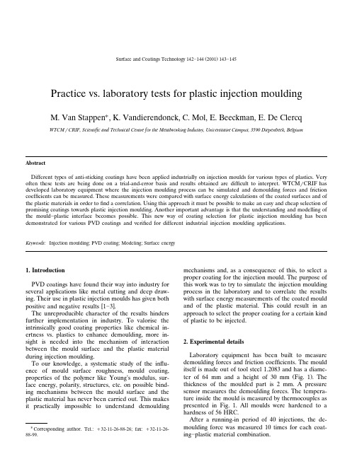
Ž.Surface and Coatings Technology142᎐1442001143᎐145Practice boratory tests for plastic injection mouldingM.Van Stappen U,K.Vandierendonck,C.Mol,E.Beeckman,E.De ClercqWTCM r CRIF,Scientific and Technical Centre for the Metalworking Industry,Uni¨ersitaire Campus,3590Diepenbeek,BelgiumAbstractDifferent types of anti-sticking coatings have been applied industrially on injection moulds for various types of plastics.Very often these tests are being done on a trial-and-error basis and results obtained are difficult to interpret.WTCM r CRIF has developed laboratory equipment where the injection moulding process can be simulated and demoulding forces and friction coefficients can be measured.These measurements were compared with surface energy calculations of the coated surfaces and of the plastic materials in order tofind a ing this approach it must be possible to make an easy and cheap selection of promising coatings towards plastic injection moulding.Another important advantage is that the understanding and modelling of the mould᎐plastic interface becomes possible.This new way of coating selection for plastic injection moulding has been demonstrated for various PVD coatings and verified for different industrial injection moulding applications.Keywords:Injection moulding;PVD coating;Modeling;Surface energy1.IntroductionPVD coatings have found their way into industry for several applications like metal cutting and deep draw-ing.Their use in plastic injection moulds has given bothw xpositive and negative results1᎐3.The unreproducible character of the results hinders further implementation in industry.To valorise the intrinsically good coating properties like chemical in-ertness vs.plastics to enhance demoulding,more in-sight is needed into the mechanism of interaction between the mould surface and the plastic material during injection moulding.To our knowledge,a systematic study of the influ-ence of mould surface roughness,mould coating, properties of the polymer like Young’s modulus,sur-face energy,polarity,structures,etc.on possible bind-ing mechanisms between the mould surface and the plastic material has never been carried out.This makes it practically impossible to understand demouldingU Corresponding author.Tel.:q32-11-26-88-26;fax:q32-11-26-88-99.mechanisms and,as a consequence of this,to select a proper coating for the injection mould.The purpose of this work was to try to simulate the injection moulding process in the laboratory and to correlate the results with surface energy measurements of the coated mould and of the plastic material.This could result in an approach to select the proper coating for a certain kind of plastic to be injected.2.Experimental detailsLaboratory equipment has been built to measure demoulding forces and friction coefficients.The mould itself is made out of tool steel1.2083and has a diame-Ž.ter of64mm and a height of30mm Fig.1.The thickness of the moulded part is2mm.A pressure sensor measures the demoulding forces.The tempera-ture inside the mould is measured by thermocouples as presented in Fig.1.All moulds were hardened to a hardness of56HRC.After a running-in period of40injections,the de-moulding force was measured10times for each coat-ing᎐plastic material combination.()M.Van Stappen et al.r Surface and Coatings Technology 142᎐1442001143᎐145144Fig.1.A cylindrical plastic part injection moulded around a mould.Surface energy was measured on the surface of the coating and on the surface of the plastic material using the model of Owens and Wendt.A Digidrop GBX apparatus has been used based on water and di-iodomethane as testing liquids.To measure the total surface energy,the dispersive surface energy and the polar surface energy are measured.Injection moulding was carried out as follows.In the first application,a polyurethane plastic material with tradename DESMOPAN 385S was injection moulded using uncoated moulds and moulds coated with,respec-tively,a TiN and a CrN coating.In the second applica-tion,three types of polymers were tested on a TiN coated mould and an uncoated mould.Two elastomers Žtrade name HYTREL G 3548W,which is a block-copolyester,and SANTOPRENE 101-73,which is a .blend of polypropylene and EPDM ,and EVOPRENE,which consists of polystyrene and butadiene.3.Results and discussionThe demoulding forces measured for the first appli-cation are given in Table 1.The demoulding forces for the second application are given in Fig.2.This demoulding behaviour has also been observed in industrial practice,so the demoulding laboratory apparatusis a good simulation of reality.To explain these results,an attempt was made to find a correlation with the surface energy measurements.Both total surface energy as well as polar surfaceTable 1Ž.Demoulding forces N for DESMOPAN Uncoated mould 7757N TiN coated mould -2810N CrN coated mould<415NŽ.Fig. 2.Demoulding forces in N for three materials:HYTREL,EVOPRENE,SANTOPRENE.energy in mJ r m 2were compared for both coated sur-Ž.faces and plastic materials Fig.3.In order to explain the demoulding behaviour,an attempt was made to make a correlation between de-moulding forces measured and the surface energy val-ues.It should be expected that when the surface energy of the coated surface is lower than the surface energy of the plastic material,an easy demoulding behaviour could result as a consequence of low material affinity between coating and plastic material.Because the ratio of polar vs.dispersive surface energy varies for the different plastic materials,both surface energy values are taken into account.For the demoulding forces measured in the first case Ž.Table 1,it could be seen that a CrNcoating,espe-cially,could offer good demoulding behaviour.When Ž.we compare Fig.3the surface energy values of DESMOPAN with the values for the mould surfaces Ž.ᎏSTAVAX s uncoated ,CrN and TiN ᎏthen it can be seen,for both total surface energy as polar surface energy,that the measured values for DESMO-Ž2.Fig.3.Total surface energies mJ r m of the different coatings and plastic materials.()M.Van Stappen et al.r Surface and Coatings Technology142᎐1442001143᎐145145Ž2.Fig.4.Polar surface energies mJ r m of the different coatings and plastic materials.PAN are lower compared to the mould surface values. This means that there is no correlation between the demoulding forces measured and the surface energy values.It seems,however,that a CrN surface has the lowest surface energy compared to a TiN coated sur-face and an uncoated surface.When one looks to the total surface energy values Ž.Fig.3,one can see that SANTOPRENE has the lowest value and HYTREL the highest.If our hypothesis was correct from the beginning,we should conclude that the demoulding force for HYTREL should be small and should be large for SANTOPRENE.One can see from Fig.2that this is not the case.When one looks at the polar surface energy values Ž.Fig.4,the three plastic materials have a lower value than the mould surface and SANTOPRENE and EVOPRENE have a lower value than HYTREL. Even when other surface energy criteria are used, e.g.the lower the energy of the mould surface theŽ.lower the demoulding force3,even then no correla-tion can be found.It can be seen that a TiN coating always increases the surface energy and,on the other hand,good de-moulding is sometimes seen, e.g.for HYTREL and DESMOPAN,and sometimes bad demoulding results, e.g.for EVOPRENE.Hence,we can conclude that,based on the surface energy values measured,no correlation could be found within the demoulding forces.Obviously,other parameters,such as roughness and injection tempera-ture,also play an important role in explaining the demoulding behaviour.In order to continue the research work to explain the demoulding behaviour,we will focus onfive industrial demonstrations and try to incorporate all relevant parameters:coating properties,plastic material proper-ties and injection parameters.4.ConclusionsNo correlation could be found between the demould-ing behaviour of plastics vs.coated moulds and the measured surface energy values.Other parameters must also influence this demould-ing behaviour.Further research will focus on other parameters like coating properties,plastic properties and injection parameters.Referencesw x1Annonymous,Big savings made with coated injection mouldingŽ.tool,Precision Toolmaker61998,138w x2O.Kayser,PVD-Beschichtungen schutzen werkzeug und¨Ž.schmelze,Kunststoffe7199598.w x3M.Grischke,Hartstoffschichten mit niedriger Klebneigung,JOT Ž.1199615.。
模具英语词汇大全

汽车冲压模具英语词汇Die / Tool= 模具Prog. Die=progressive die 级进模Ball bearing guide posts and bushings=球形滚珠导柱和轴套Casting die=铸造模Cage=套Part=钣件Rigidity=强度Die material=制模材料Thin=薄Tool design=模具设计Strip design=料条设计Using material thickness radii where sharp corners are shown on the part reduces the occurrence of chipped punch or die corners in the tool. =在尖角处使用与材料厚度一样的R角减少冲头碎裂或模具中有“刀口”Tool design approval=模具设计审核Tool design modification/revision=模具设计更改Tool parts design (detail) = 模具钣件设计(详细)Heeled die sets, internally heel form & trim sections=带箱根的模架,成形与切刃冲头带导引FMC Make=保丽龙制作Construction method=结构方法modification= 更改Check & measure=检查& 测试Machining= 机器加工Large machining=在大型机器上加工上下模架(铣、车等)Small machining=在小型机器上加工模块等Lower die trim inserts=下模切刃块Lower trim inserts retainer=下模切刃块承盘Assemble inserts=组立镶块Punch stripping plates=冲头压料板Assembly=组立Trim punch backing plates=切刃冲头背板NC Machining=NC雕刻加工Stripper window inserts=料条窗户镶块Fitting=研磨组立Spotting=合模Die tryout=试模Cushing stroke=缓冲行程Dowel pin=定位销Guide lift pin=导引升降销Assemble gas spring=安装氮气缸Stamp parts=冲钣件Adjustment=调试Run off parts=冲钣件Lower trim steels=下刃块Hit parts=冲钣件Section=冲头断面Lifters=提升器Trim punch=切刃冲头Coil=卷材jack screw hole=起重[千斤顶]螺旋孔Guide block=导引块Die set, lower plate=下模架Guide the coil through the tool=导引卷材Die set, upper plate=上模架layout inspection=全尺寸检验Die inspection & approval=模具检查和审核Stretch carriers=拉伸运送装置delivery=发货Punch stripping plates=冲头压料板Rejected=拒收Trim punch backing plates=切刃冲头背板Scrapped=报废Stripper window inserts=料条窗户镶块Rework=返工Heel plates=背托stop block=停止块Prepare for delivery=准备发货Hydro form 液压成形Key=键Shear=剪切For locating retainer blocks=承盘键Sensor=传感器For holding buttons or pilots=冲母座或导销键Stretch web=拉伸网For fixed heel or positive stop=镶根键Layout the parts=设计钣件Construction method=结构方法Preceding into the design=继续设计Manual Surface Grinder=手动平面磨床Guide the coil through the tool=导引卷材Spotting red=合模用丹红Checking aid /checking gage=检具Layout ink=试模用蓝墨水Jig=夹具Masking tape=黄色不透明胶带(遮蔽胶带) Fixture=夹具Pliers=尖嘴钳,老虎钳Ball bearing guide posts and bushings=球形滚珠轴套Cresent wrench=可调扳手Guide post=导柱Bushings=导套Pump pipe=泵管Using material thickness radii where sharp corners are shown on the part reduces the occurrence of chipped punch or die corners in the tool. =在尖角处使用与材料厚度一样的R 角减少冲头碎裂或模具中有“刀口”CMM=三次元测量仪Symmetric=对称的The axis of symmetry=对称轴Technical=技术上的Diagonal=对角线Heeled die sets, internally heel form & trim sections=带箱根的模架,成形与切刃冲头带导引One two three block=一二三模块Adjustable parallels=可调平行块Stop block=阻止块Granite Table=花岗岩平台Backing Plate=背板Plotter= .描绘器, 图形显示器, 绘图器, 坐标自记器, 标图员Shoulder Bolt=肩头螺丝(Stripper bolt)Belt Sander=带磨机Keeper Block=行程块Metal Cutting Band Saw=立式带锯床Corner Guide Block=导块Blanchard Grinder=大型平面磨床Dowel pin=定位销Joe Blocks=精密量块Set Screw=螺塞Whirly Gig=筒夹式冲子成形器Jig & fixture =夹具Chamfer Tools=倒角刀具组Checking fixture=检具Angle Plate=L形直角座Guide Block=导块Gage Pins=英寸塞规Plunger=柱塞Sine Plate (magnetic)=正弦磁台Pierce=冲孔Flute End Mill=硬质合金钢铣刀Wear Strip=耐磨板Mill Cutter=波纹粗铣刀(标准型)Mating area=组立的接触面C’bore/ counter bore=六角沉头铣刀Accommodate=适应Radius Dresser=砂轮修整器Wiping hard (very shiny)= 过分摩擦闭合[接触](闪光)Boring Head & Boring Bar=搪孔器、搪刀杆Pin=销Increase the die clearance between the form steels=增加成形块间隙Reamer=绞刀Clearance=间隙Approval=确认Oil paper=油纸Impact wrench=气动扳手0-11” Micrometer=0-11”千分尺Air pin=空气销Trim line=切边bumper[‘bQmpE(r)] n.缓冲器+/-0.5mm unless otherwise specified除非另有规定,否则公差为+/-0.5mmV endor [‘vendE(r), -dC:(r)] n.卖主Part tolerance=钣件公差stripper layout=排样图Ball nose=球刀drawing of panel #987415&16=钣件设计图(公差)Bore=镗Line tap=攻丝校直Arbor =柄轴;心轴Borer=镗刀,镗床Drill chuck=钻夹头Chamfer=倒角Button=冲母座Radius=半径Nitrogen Cylinder=氮气缸Coolant=切削液Pilot=导销Punch=冲头Retainer=承盘Distribution Blocks=接头座Button=冲母座Screw=螺丝Hose Straps=软管夹(塑料)Shop=车间Flat Feet Keepers=顶料销Crib=仓库Ejector Pin=顶出销CNC mill= CNC机床Spring=弹簧Jack=千斤顶Straight Port Adapter=直管接头Strips=料条Y-205 Hose=软管(塑料)Styrofoam [`stairEfEum]n.聚苯乙烯泡沫塑料(保丽龙材料)Short Neck Adapter=短接头Cut off=落料45。
模具设计外文翻译

Four-Cavity Hot-runner Stack Mold for Producing Automotive Inner SillTrim Made from PolypropyleneTo produce the inner sill trim used in an automobile as the transition the carpeting and vehicle frame, a four-cavity hot-runner stack mold was designed. Interconnecting tubes with a sliding fit inate the thermal expansion of the hot-runner systenm ..Depending on the car mold ,there is a left-hand and a right-hand version as well as a long and a short sill.General Mold DesignThe dimensions of the inner sills are 1250 mm*60 mm*2.5 mm, so that the parts are relatively large in area but with comparatively little material content (fig.1). The molded parts weigh 180 and 150 g respectively. Producing these parts by means of a stack mold was the obvious solution, as this doubles the output of the injection molding machine although the claming force requirements remain the same. The name of parts needed to obtain optimum machine utilization resulted in a four-cavity mold with two different cavities for the left-hand and right-hand versions (fig.2 to 5)) . The variation in the lengh of the trim is taken care of by interchangeable mold inserts. To achieve warp-free polypropylene copolymer (hostalon ppr 1042,supplier: Hoechst AG , Germany)required that the flow lengths be limited to approximately 170 mm. Five injection points are needed to along the inside of the trim.The design of the mold provides for simultaneous opening of the two part lines with the aid of two racks (40) and a pinion (36) for each side. As it is essential that no gate marks show on the front of the inside. The mounting attachment and spacers for the carpeting, which require ejector assistance for part release, are also located in this area ,however. Some of the mounting attachment are not at right angles to the part line ,so that hydraulically operated ejectors have been incorporated in hot-runner plates (3) and (5). The cylinders have been specially designed to permit utilization in the immediate vicinity of the hot-runner manifolds at temperatures of about 260 cMold Temperature ControlThree independent circuits have been provide in cach of the mold plates (2) and (3) as well as (5) and (6) for mold temperature control. This permits the temperatures of the outer regions of the 1250 mm long part to be controlled independently of the center region .At a mold width of 1500 mm and with several channels per plate, division into several circuits is also much more favorable with regard to pressure losses, which otherwise would occur.Hot-Rnner DesignA hot-runner system utilizing indirectly heated thermally conductive torpedodes has been selected to distriute melt within the mold.Incorporating the hydraulically operated ejectors in reduce the available space ,thereby forcing a partial reduction of the torpedo diameter.By modifying other design parameters, it was possible to compensate for the resulting change in heat transfer. The chosen injection points require the hot-runner manifold to be 888 mm long. To reduce the ensuing thermal expansion of approx .2 mm total, four indibidual manifold blocks 8 to 11 that are connected to one another by means ofmelt-conbeying pipes 12 to 14 with sliding fits have been provided. The feed pipes 15 divides the central manifold 11 into a right-hand and a left-hand half, each with its own termperature control Eachmaniflod contains four thermally conducting torpecdoes. The left-hand side of manifold block 11 contains only three cartridge heaters, the heating for the feed pipe compensating for any possible heat loss in this area. It is thus possible to vary the temperature at each gate.The melt-conveying pipes of the hot-runner system are fitted with connercially available heater bands with integral thermocouples. The hot-runner system thus contains five heater circuits for the manifold blocks and four heater circuits four the melt-conveying pipes 12 and 13 was not needed. These pipes received adequate heat from the neighboring manifold blocks 8 to 11. No measurable temperature loss occurred .All of the cartridge heaters have the same dimension of 200 mm*16 mm dia. and a heating capacity of 1250w. The watt density in this case lies at 12.5w/cm ,a value guaranteeing long cartridge life even with negligible play in the heater cartridge well. The result is an installed heating capacity of 5000w per manifold or heater circuit power is supplied bia a temperature controller with thyristorcontrol and an output current of 25 A The four controllers for the melt-conveying pipes were chosen to have the same specifications, although an output current of 6 to 10 A would have been adequate. This mesure that if one temperature controller fails, operation of the most important manifold can be ensured by a simple wiring change. The total installed heating capacity thus amounts to 25 kw. The manifolds were designed to have 250w per kg .with this specific heating capacity, balanced heating can be achieved for temperatures of up to approx. 300 c at a mold temperature of 40 c .The warm-up time is approximately 15 minutes, not including the soft start provided bu the controls. The integral soft start limits the supplied power to 50% and thus protects the cartridge heaters.The manifold popes have been produced from hot work steel to ensure that there is no loss in hardness at a possible temperature of 300 c .The sealing lips which slide with the thermal expansion are designed to provide favorable flow characteristics. They have additionally been protected against proven to be leakproof in operation.The threaded section has been produced with a toleranced press fit. The feed pipe 15 is providedwith a decom-pression bushing 16 at the end; this bushing has a stroke of about 5 mm.The length of the feed pipe is such that no dripping material can possibly drop into the parting line of the mold .The melt covers a distance of 940 mm to the farthest gates .The nearest gates are 530 mm away from the decompression bushing. During operation,the hot runner is completely filled with melt. The pressure is thus transmitted almost uniformly up to the individual gates in the stationary melt (or during creep flow ).The holding pressure is therefore also uniformly applied. When the melt is flowing ,however, thereis a pressure drop along the flow path. A moldflow analysis conduted with the objective of providing identical pressure losses in the flowing melt up to each gate yielded different diameters for the runner channels. The primary runner channel has a diameter of 18 mm ,while the vertical secondary runners have a diameter of 6 mm in the center of the mold and one of 8 mm in the outer regions.The torpedoed\s are 110 mm long,17 mm in diameter with an insulating gap of 7.5 mm. At a hot runner manifold temperature of 260 c ,the temperature at the torpedo tip is still at least 235 c. This value is sufficient for polypropylene. Start-up even after a prolonged production inter-ruption does not present any problems. The gate inserts 21 are insulated from the mold plate by a 0.5 mm annular air pocket.A CuCrZr alloy (material no.2.1293) wsa selected for the torpedoes (3) .The torpedoes have been chemically plated with hard nickel 4 to prevent a chemical reaction between the copper and the pp and then subsequently coated with thin ;ayer of chrome to give better adhesive properties.The four hot-runner manifolds 8 to 11 have been provided with central pressure pads 17and 18 which serve to locate the manifolds and transmit the resulting forces into the adjacent mold plates .Four dowel pins in grooves prevent the manifolds from turning. The manifolds are not bolted to the adjacent nozzle plates, but are allowed to float. The distance between the torpedo retainer bushings 20 has been over dimensioned by 0.1 mm in relation to the center frame 4 to ensure that the sustem remains leak-proof even in the eyent of plate deflection or an angular displacement . It was found that, in spite of the size of the mold, the increased thermal expansion of the hot-runner system with respect to the mold frame is sufficient to provide an difficient seal . As a result of the separation into four separate manifolds with axially sliding melt conveying pipes, hermal expansion perpendicular to the mold axis did not have to be taken into account. The torpedoes themselves were shortened by 0.4 mm when cold. As they heat up ,they pxpand into the precalculated insulating ;lates 22 clad with aluminum foil to reduce radiation losses.The total volume of melt in the system is approxi-mately 840; the volume of the four sill trim moldings is 650. The ensures a short residence time for the melt in the manifold system. Changing to a different color for the sill trim does not present any problems during production and can be accomplished quickly.MOLD CONSTRUCTIONMolds for processing of thermosetting molding compounds are generally heated electrically. The heat needed for the crosslinking reaction is drawn from the mold .once in contact with the cavity surface the viscosity of the melt passes through a minimum,i.e. the melt becomes so low in viscosity that it can penetrate into very narrow gaps and produce flash. The molds must thus exhibit very tight fit ,while at the same time providing for adequate venting of the cavity. These largely oppssing requirements are the reason that formation of flast cannot be completely climinated. Molds should be designed to be extremely stiff so that formation of flash are avoided. The use of pressure sensors to determine and monitor the injection pressures, on the basis of which the mechanical properties of the mold are calculated,is recom-mended. The pressure actually required depends on the size an geometry of the molded parts. Material selection is of great importance with regard to the life wcpectancy of the molds, a subject which must already be addressed during the quoting phase what was said in this regard for thermoplastics applies analogously here. Through-hardening steels are to be preferred for the part-forming surfaces and must exhibit a resistance to tempering consistent with the relatively high operating temperatures of stick,e.g. unsaturated polyester resins, steels with >13%chrome content have proven useful, e.g.tool steel no. 1.208, since the thermosetting molding compounds are sometimes modified with abrasive fillers, special attention must be given to the resulting wear. Fillers such as stone flour, mica, glass gibers and the like , for instance ,promote wear. In wear prone regions of the mold such as the gate, for example, metal carbide inserts should be provided. Other wear-prone mold components should gener-ally be designed as easily replace inserts.EJECTION/VENTINGDepending on the geometry of molded part and type of molding compound, different amounts ofdraft for part release must be provided,usually between 1 and 3 .At the time of ejection,theroset parts exhibit very little shrinkage because of the relatively high temperature. As a result, parts are not necessarily retained on the mold cores, but rather may be held in the cavity by a vacuum. To avoid problems during production, measures must be taken to ensure that the parts can always be ejected from the same half of the mold .。
模具毕业设计外文翻译(英文+译文)
Injection MoldingThe basic concept of injection molding revolves around the ability of a thermoplastic material to be softened by heat and to harden when cooled .In most operations ,granular material (the plastic resin) is fed into one end of the cylinder (usually through a feeding device known as a hopper ),heated, and softened(plasticized or plasticized),forced out the other end of the cylinder, while it is still in the form of a melt, through a nozzle into a relatively cool mold held closed under pressure.Here,the melt cools and hardens until fully set-up. The mold is then opened, the piece ejected, and the sequence repeated.Thus, the significant elements of an injection molding machine become: 1) the way in which the melt is plasticized (softened) and forced into the mold (called the injection unit);2) the system for opening the mold and closing it under pressure (called the clamping unit);3) the type of mold used;4) the machine controls.The part of an injection-molding machine, which converts a plastic material from a sold phase to homogeneous seni-liguid phase by raising its temperature .This unit maintains the material at a present temperature and force it through the injection unit nozzle into a mold .The plunger is a combination of the injection and plasticizing device in which a heating chamber is mounted between the plunger and mold. This chamber heats the plastic material by conduction .The plunger, on each stroke; pushes unbelted plastic material into the chamber, which in turn forces plastic melt at the front of the chamber out through the nozzleThe part of an injection molding machine in which the mold is mounted, and which provides the motion and force to open and close the mold and to hold the mold close with force during injection .This unit can also provide other features necessary for the effective functioning of the molding operation .Movingplate is the member of the clamping unit, which is moved toward a stationary member. the moving section of the mold is bolted to this moving plate .This member usually includes the ejector holes and mold mounting pattern of blot holes or “T” slots .Stationary plate is the fixed member of the clamping unit on which the stationary section of the mold is bolted .This member usually includes a mold-mounting pattern of boles or “T” slots. Tie rods are member of the clamping force actuating mechanism that serve as the tension member of the clamp when it is holding the mold closed. They also serve as a gutted member for the movable plate .Ejector is a provision in the clamping unit that actuates a mechanism within the mold to eject the molded part(s) from the mold .The ejection actuating force may be applied hydraulically or pneumatically by a cylinder(s) attached to the moving plate, or mechanically by the opening stroke of the moving plate.Methods of melting and injecting the plastic differ from one machine to another and are constantly being implored .conventional machines use a cylinder and piston to do both jobs .This method simplifies machine construction but makes control of injection temperatures and pressures an inherently difficult problem .Other machines use a plasticizing extruder to melt the plastic and piston to inject it while some hare been designed to use a screw for both jobs :Nowadays, sixty percent of the machines use a reciprocating screw,35% a plunger (concentrated in the smaller machine size),and 5%a screw pot.Many of the problems connected with in ejection molding arise because the densities of polymers change so markedly with temperature and pressure. thigh temperatures, the density of a polymer is considerably cower than at room temperature, provided the pressure is the same.Therefore,if molds were filled at atmospheric pressure, “shrinkage” would make the molding deviate form the shape of the mold.To compensate for this poor effect, molds are filled at high pressure. The pressure compresses the polymer and allows more materials to flow into the mold, shrinkage is reduced and better quality moldings are produced.Cludes a mold-mounting pattern of bolt holes or “T” slots. Tie rods are members of the clamping force actuating mechanism that serve as the tension members of clamp when it is holding the mold closed. Ejector is a provision in the calming unit that actuates a mechanism within the mold to eject the molded part(s) form the mold. The ejection actuating force may be applied hydraulically or pneumatically by a cylinder(s) attached to the moving plate, or mechanically by the opening stroke of the moving plate.The function of a mold is twofold: imparting the desired shape to the plasticized polymer and cooling the injection molded part. It is basically made up of two sets of components: the cavities and cores and the base in which the cavities and cores are mounted. The mold ,which contains one or more cavities, consists of two basic parts :(1) a stationary molds half one the side where the plastic is injected,(2)Moving half on the closing or ejector side of the machine. The separation between the two mold halves is called the parting line. In some cases the cavity is partly in the stationary and partly in the moving section. The size and weight of the molded parts limit the number of cavities in the mold and also determine the machinery capacity required. The mold components and their functions are as following:(1)Mold Base-Hold cavity (cavities) in fixed, correctposition relative to machine nozzle.(2)Guide Pins-Maintain Proper alignment of entry into moldinterior.(3)Spree Bushing (spree)-Provide means of entry into moldinterior.(4)Runners-Conroy molten plastic from spree to cavities.(5)Gates-Control flow into cavities.(6)Cavity (female) and Force (male)-Control the size,shape and surface of mold article.(7)Water Channels-Control the temperature of mold surfacesto chill plastic to rigid state.(8)Side (actuated by came, gears or hydrauliccylinders)-Form side holes, slots, undercuts and threaded sections.(9)Vent-Allow the escape of trapped air and gas.(10)Ejector Mechanism (pins, blades, stripper plate)-Ejectrigid molded article form cavity or force.(11)Ejector Return Pins-Return ejector pins to retractedposition as mold closes for next cycle.The distance between the outer cavities and the primary spree must not be so long that the molten plastic loses too much heat in the runner to fill the outer cavities properly. The cavities should be so arranged around the primary spree that each receives its full and equal share of the total pressure available, through its own runner system (or the so-called balanced runner system).The requires the shortest possible distance between cavities and primary sprue, equal runner and gate dimension, and uniform culling.注射成型注射成型的基本概念是使热塑性材料在受热时熔融,冷却时硬化,在大部分加工中,粒状材料(即塑料树脂)从料筒的一端(通常通过一个叫做“料斗”的进料装置)送进,受热并熔融(即塑化或增塑),然后当材料还是溶体时,通过一个喷嘴从料筒的另一端挤到一个相对较冷的压和封闭的模子里。
项目 模具英语

项目模具英语模具英语是指在模具制造和使用过程中所涉及的英语词汇和表达方式。
模具是一种用于制造各种产品的工具或设备,通常由金属或塑料制成。
在国际贸易和合作中,模具行业的英语交流已经成为一种必备技能。
以下是模具英语的标准格式文本:一、模具制造过程中的英语词汇和表达方式1. 模具设计(Mold Design)- Design concept: 设计理念- 3D modeling: 三维建模- Draft angle: 脱模锥度- Parting line: 分模线- Core and cavity: 芯和腔- Cooling system: 冷却系统- Ejection system: 脱模系统- Runner system: 浇注系统- Gate design: 浇口设计- Mold flow analysis: 模流分析2. 模具制造(Mold Manufacturing)- CNC machining: 数控加工- EDM (Electrical Discharge Machining): 电火花加工 - Wire cutting: 线切割- Grinding: 磨削- Polishing: 抛光- Assembly: 组装- Trial production: 试产- Inspection: 检验- Modification: 修改3. 模具使用(Mold Application)- Injection molding: 注塑- Blow molding: 吹塑- Compression molding: 压塑- Thermoforming: 热成型- Extrusion molding: 挤出成型- Rotational molding: 旋转成型- Overmolding: 双色注塑- Insert molding: 嵌入式注塑- Molding defects: 成型缺陷- Mold maintenance: 模具维护二、模具行业常用的英语表达方式和句型1. 询盘和报价(Inquiry and Quotation)- We are interested in your mold products and would like to request a quotation.- Could you please provide us with the price list for your mold products?- Can you give us a detailed breakdown of the costs involved in manufacturing the mold?- We would like to know the delivery time for the mold products.2. 技术交流和合作(Technical Communication and Cooperation)- We would like to discuss the mold design and specifications in detail.- Could you provide us with the CAD files or 3D drawings of the mold?- We are open to any suggestions or improvements regarding the mold design.- We are willing to cooperate with your company on mold manufacturing and development.3. 合同和支付(Contract and Payment)- We would like to sign a contract for the mold manufacturing project.- What are the payment terms and conditions for the mold products?- We will make the payment in installments according to the agreed schedule.- The payment will be made by bank transfer or letter of credit.4. 售后服务和保修(After-sales Service and Warranty)- We expect a warranty period for the mold products.- In case of any problems or defects, we would like to know your after-sales service policy.- Could you provide us with the spare parts and maintenance manual for the mold?- We appreciate your prompt response and support in resolving any issues with the mold.以上是关于模具英语的标准格式文本,涵盖了模具制造过程中的英语词汇和表达方式,以及模具行业常用的英语表达方式和句型。
模具加工方法英语词汇大全

模具加工方法英语词汇大全在模具加工领域,掌握相关英语词汇是非常重要的。
本文将为你提供一个模具加工方法英语词汇大全,帮助你更好地理解和交流相关的知识。
1. 模具加工方法基础词汇Mold (模具)•Cavity: 空腔•Core: 芯子•Ejector Pins: 推杆•Draft Angle: 脱模锥度•Runner: 浇口Machining (加工)•Milling: 铣削•Turning: 车削•Drilling: 钻削•Grinding: 磨削•Boring: 镗削Surface Treatment (表面处理) •Polishing: 抛光•Electroplating: 电镀•Anodizing: 阳极氧化•Coating: 涂层•Sandblasting: 喷砂Measurement (测量)•Caliper: 卡尺•Micrometer: 千分尺•Height Gauge: 高度规•CMM (Coordinate Measuring Machine): 三坐标测量机•Profile Projector: 轮廓投影仪2. 模具加工方法高级词汇CNC Machining (数控加工)•CNC Milling: 数控铣削•CNC Turning: 数控车削•CNC Grinding: 数控磨削•CNC Wire EDM (Electrical Discharge Machining): 数控线切割•CAM (Computer-ded Manufacturing): 计算机辅助制造Injection Molding (注塑)•Mold Design: 模具设计•Mold Flow Analysis: 模流分析•Mold Temperature Control: 模具温度控制•Gate Design: 浇口设计•Venting: 排气Die Casting (压铸)•Die Design: 压铸模具设计•Die Lubrication: 压铸模具润滑•Die Casting Defects: 压铸缺陷•Cold Chamber Die Casting: 冷室压铸•Hot Chamber Die Casting: 热室压铸Stamping (冲压)•Progressive Die: 渐进模具•Blanking: 冲裁•Piercing: 穿孔•Bending: 弯曲•Deep Drawing: 深冲3. 模具加工方法其他相关词汇Mold Materials (模具材料)•Tool Steel: 工具钢•Stnless Steel: 不锈钢•Aluminum: 铝•Copper: 铜•Plastic: 塑料Mold Components (模具部件)•Guide Pins: 导柱•Ejector Sleeves: 推杆套筒•Sprue Bushing: 浇口套筒•Inserts: 嵌件•Lifter: 脱模销Mold Mntenance (模具维护)•Cleaning: 清洁•Lubrication: 润滑•Repr: 修复•Storage: 存储•Replacement: 更换以上是一个模具加工方法英语词汇大全,涵盖了基本和高级词汇以及其他相关词汇。
注塑成型的模具设计外文翻译
Figure 1. Organization of the IKEM Project2 Intelligent Mold Design ToolThe mold design tool in its basic form is a Visual Basic application taking input from a text file that contains information about the part and a User Input form. The text file contains information about the part geometry parsed from a Pro/E information file. The input is used to estimate the dimensions of mold and various other features.2.1 Literature ReviewDesign of molds is another stage of the injection molding process where the experience of an engineer largely helps automate the process and increase its efficiency. The issue that needs attention is the time that goes into designing the molds. Often, design engineers refer to tables and standard handbooks while designing a mold, which consumes lot of time. Also, a great deal of time goes into modeling components of the mold in standard CAD software. Differentresearchers have dealt with the issue of reducing the time it takes to design the mold in different ways. Koelsch and James have employed group technology techniques to reduce the mold design time. A unique coding system that groups a class of injection molded parts, and the tooling required ininjection molding is developed which is general and can be applied to other product lines.A software system to implement the coding system has also been developed. Attempts were also directed towards the automation of the mold design process by capturing experience and knowledge of engineers in the field. The development of a concurrent mold design system is one such approach that attempts to develop a systematic methodology for injection mold design processes in a concurrent engineering environment. The objective of their research was to develop a mold development process that facilitates concurrent engineering-based practice, andFigure 2. Organization of the Mold Design Module.While most of the input, like the number of cavities, cavity image dimensions, cycle time are based on the client specifications, other input like the plasticizing capacity, shots per minute etc., can be obtained from the machine specifications. The output of the application contains mold dimensions and other information, which clearly helps in selecting the standard mold base from catalogs. Apart from the input and output, the Figure 2 also shows the various modules that produce the final output.2.5 Framing rulesAt this stage, the expert’s knowledge is represented in the form of multiple If-Then statements. The rules may be representations of both qualitative and quantitative knowledge. By qualitative knowledge, we mean deterministic information about a problem that can be solved computationally. By qualitative we mean information that is not deterministic, but merely followed as a rule based on previous cases where the rule has worked. A typical rule is illustrated below:If Material = “Acetal” AndRunner Length <= 3 AndRunner Length > 0 ThenRunner Diameter =0.062End IfWhen framing the rules it is important that we represent the information in a compact way while avoiding redundancy, incompleteness and inconsistency. Decision tables help take care of all the above concerns by checking for redundancy and comprehensive expression of the problem statement. As an example, in the process of selecting an appropriate mold base, the size of mold base depends on the number of cavities and inserts. To ensure that all possible combinations of。
模具中英对照
模具中英对照模具是一种用来制造复杂形状的工具,广泛应用于汽车、航空、电子、医疗等领域。
在国际贸易中,模具领域是一个重要的行业,涉及到的技术术语和行业术语繁多,因此,建立起一个模具中英对照的文档对于学习和应用模具领域具有重要的意义。
下面我们将列出一些常见的模具术语及其中英对照:1. 模具设计:mould design2. 模具制造:mould making3.模具材料:mould material4. 模具钢:mould steel5. 模具试样:mould trial sample6. 模具寿命:mould life7. 塑料注塑模具:plastic injection mould8. 金属冲压模具:metal stampingmould9. 模具零件:mould parts10. 设计参数:design parameter11. 模具尺寸:mould dimension12. 模具重量:mould weight13. 模具结构:mould structure14. 成型工艺:forming process15. 模具表面处理:mould surface treatment16. 冷却系统:cooling system17. 模具加工:mould machining18.精度控制:precision control19. 模具维护:mould maintenance20. 模具修复:mould repair随着模具行业的发展,中英对照文档需要不断地进行更新和完善。
在实际应用中,我们需要根据需求来确定需要掌握的技术和行业术语,并及时查阅相关的中英对照文档,以便更好地理解和使用模具技术。
除了上述列出的术语,模具领域还涉及到很多具有专业性的技术术语和行业术语,例如模具热处理、模具注塑成型、模具表面处理等方面的专业术语。
因此,掌握和应用模具技术需要具备较高的专业素养和知识储备,这需要我们持续地学习、实践和总结。
项目 模具英语
项目模具英语一、引言模具(Mold),是创造工业中常用的一种工具,用于创造成型产品。
模具创造是一个复杂而精细的过程,需要涉及到多个环节和专业知识。
在国际交流与合作中,掌握模具英语是非常重要的,本文将介绍与模具相关的英语词汇、短语和常用句型,以匡助读者更好地理解和应对模具创造过程中的沟通需求。
二、模具英语词汇1. Mold:模具2. Die:模具3. Injection mold:注塑模具4. Casting mold:铸造模具5. Press mold:压铸模具6. Mold cavity:模具腔7. Core:芯子8. Ejector pin:顶针9. Runner system:流道系统10. Cooling system:冷却系统11. Mold release agent:脱模剂12. Mold design:模具设计13. Mold manufacturing:模具创造14. Mold maintenance:模具维护15. Mold repair:模具修复16. Mold trial:模具试模17. Mold flow analysis:模流分析18. Mold steel:模具钢19. Mold base:模具底板20. Mold cavity surface:模具腔面三、模具英语短语1. Mold making:模具制作2. Mold polishing:模具抛光3. Mold assembly:模具组装4. Mold testing:模具测试5. Mold modification:模具修改6. Mold maintenance and repair:模具维护和修复7. Mold design and development:模具设计与开辟8. Mold manufacturing process:模具创造过程9. Mold flow simulation:模具流动摹拟10. Mold release agent application:脱模剂的应用11. Mold temperature control:模具温度控制12. Mold surface treatment:模具表面处理13. Mold quality inspection:模具质量检验14. Mold life cycle:模具寿命周期15. Mold production efficiency:模具生产效率四、模具英语常用句型1. Could you please provide me with the mold design specification?(请提供模具设计规范好吗?)2. We need to modify the mold cavity to meet the product requirements.(我们需要修改模具腔以满足产品要求。
冲压模具设计毕业外文翻译 中英文翻译 外文文献翻译
冲压模具设计毕业外文翻译中英文翻译外文文献翻译毕业设计(论文)外文资料翻译系部:专业:姓名:学号:外文出处: The Pofessional English of DesignManufacture for Dies & Moulds附件: 1.外文资料翻译译文,2.外文原文。
指导教师评语:签名:年月日附件1:外文资料翻译译文冲压模具设计对于汽车行业与电子行业,各种各样的板料零件都是有各种不同的成型工艺所生产出来的,这些均可以列入一般种类“板料成形”的范畴。
板料成形(也称为冲压或压力成形)经常在厂区面积非常大的公司中进行。
如果自己没有去这些大公司访问,没有站在巨大的机器旁,没有感受到地面的震颤,没有看巨大型的机器人的手臂吧零件从一个机器移动到另一个机器,那么厂区的范围与价值真是难以想象的。
当然,一盘录像带或一部电视专题片不能反映出汽车冲压流水线的宏大规模。
站在这样的流水线旁观看的另一个因素是观看大量的汽车板类零件被进行不同类型的板料成形加工。
落料是简单的剪切完成的,然后进行不同类型的加工,诸如:弯曲、拉深、拉延、切断、剪切等,每一种情况均要求特殊的、专门的模具。
而且还有大量后续的加工工艺,在每一种情况下,均可以通过诸如拉深、拉延与弯曲等工艺不同的成形方法得到所希望的得到的形状。
根据板料平面的各种各样的受应力状态的小板单元体所可以考虑到的变形情形描述三种成形,原理图1描述的是一个简单的从圆坯料拉深成一个圆柱水杯的成形过程。
图1 板料成形一个简单的水杯拉深是从凸缘型坯料考虑的,即通过模具上冲头的向下作用使材料被水平拉深。
一个凸缘板料上的单元体在半径方向上被限定,而板厚保持几乎不变。
板料成形的原理如图2所示。
拉延通常是用来描述在板料平面上的两个互相垂直的方向被拉长的板料的单元体的变形原理的术语。
拉延的一种特殊形式,可以在大多数成形加工中遇到,即平面张力拉延。
在这种情况下,一个板料的单元体仅在一个方向上进行拉延,在拉长的方向上宽度没有发生变化,但是在厚度上有明确的变化,即变薄。
- 1、下载文档前请自行甄别文档内容的完整性,平台不提供额外的编辑、内容补充、找答案等附加服务。
- 2、"仅部分预览"的文档,不可在线预览部分如存在完整性等问题,可反馈申请退款(可完整预览的文档不适用该条件!)。
- 3、如文档侵犯您的权益,请联系客服反馈,我们会尽快为您处理(人工客服工作时间:9:00-18:30)。
通过控制金属模具的温度可将仅200℃的蒸竹粉用于注塑[摘要]通过控制金属模具的温度可在注塑中尝试添加蒸竹粉。
竹粉放在一个小压力容器内在200℃下蒸了20分钟。
蒸粉的热流动试验是为了便于进行粉末流动性的研究。
粉末在160-220℃具有流动性,其中在180-200℃具有良好的流动性。
注塑在180℃或200摄氏度的注射温度和80-160℃的金属模具温度的条件下进行。
通过这个过程可以获得产品。
特别的,在金属模具温度在140或160℃时可获得拥有类似光泽表面的塑料产品。
注射温度影响着注射压力;注射温度和金属模具温度较高时,应在低压下往金属模具内注入熔融材料。
然而,材料在金属模具内的流动性并没有影响到产品的表面纹理。
引言利用木质材料作为工业材料来使用被预计将是有效的。
然而,传统的木质材料加工方法例如直接加工或塑料成型等存在着工作效率和加工性较差等问题。
由于需要将木质材料作为用于进行批量生产时使用的工业材料,其生产力应得到提高。
此外,需要更有效的方法使木质材料用于成型任意形状的产品。
为了解决这些问题,作者开发了一个木质材料注塑成型的方法。
材料的流动性是注射成型的一个重要因素。
在压力和热量的作用下,木质材料由于软化以及分解成木质素和半纤维素形成液体流动状态(Yamashita et al., 2007)。
Miki et al. (2004)用木粉的饱和水溶液通过注射成型制造了复杂形状的产品。
然而,由于水在加热时会产生的水蒸气和热解气体,使得材料中的水在成型过程中起着负面影响。
此外,据报道,在木粉饱和水溶液注塑成型时不可以使用传统的电动注射机所使用的热塑性塑料。
(Miki et al., 2005)为了解决这些问题,木质材料应在干燥条件下具有良好的流动性以便于成型。
然而,据报道,在加热干燥木材时其软化点的温度提高了(Hillis and Rozsa, 1985)。
因此,仅使用木质材料进行注塑是很困难的。
另一方面,通过加热和水制备的木质材料由于在成型之前进行分解被视为一种有效的方式。
Takahashi et al. (2010)报道,通过蒸汽制备的木粉其热流动温度降低。
此外,作者进行了一次蒸竹粉的注射实验,并证明通过蒸汽制备的粉末,其注射能力得道提高(Kajikawa and Iizuka, 2013)。
在这项研究中,尝试使用了烘干状态的蒸竹粉用于注塑。
注塑机构由一个注射部分和一个金属模具部分组成。
更为可取的是注射温度高使得材料呈流体状态。
另一方面,金属模具的温度应该较低以便于模制产品得到有效的冷却。
但是当金属模具温度过低时,金属模具内的材料流动不充分。
出于这个原因,我们在注塑时应试图控制金属模具温度。
在实验中,竹粉被蒸制过,且其流动性已经被热流动性实验研究过。
此外,我们进行了使用蒸竹粉的注射成型测试,并评估了金属模具温度对模制产品外观和成型压力变化的影响。
1 材料和方法1.1 准备材料以竹粉作为材料。
首先,竹子经过自动进料刨床加工获得竹屑。
然后,竹屑经过铣削机床进一步被粉碎。
筛取直径为300微米以下的竹粉用于这个实验。
图1(a)展示了粉末的粒度分布。
在这个图示中,粉末粒度主要集中在75-300微米。
使用一个小型压力容器来蒸制竹粉。
通过加热装满水和粉末的小型压力容器生成饱和水蒸气来处理粉末。
所制备的粉末的含水量应是在蒸制前准备粉末干重的200%。
粉末在200℃下蒸制20分钟。
蒸制后,粉末置于30℃的一个风干的状态下干燥。
此外,粉末在105℃下干燥以便于烘干至实验前的状态。
图1(b)和(c)分别显示蒸制后和未蒸制的竹粉表象。
蒸制后粉末的颜色变为姜黄色。
图1:(a)竹粉的粒度分布;(b)竹粉蒸制前的外观;(c)竹粉蒸制后的外观。
1.2 热流实验为了研究蒸竹粉的流动性,我们依据了JIS K 7210设计了这个热流动试验。
在流动性实验中我们使用了毛细管流变仪(日本岛津公司测试用CFT-500D)。
测试缸体外圆柱直径为11mm,模具型腔直径为2mm长度为8mm。
首先,将测试缸体加热到测试温度f T。
将干重1.5g的粉末放入缸中并且插入活塞。
在这种状况下,粉末预热6分钟。
活塞在预热3分钟后排出多余气体后加压。
之后活塞以49Mpa压力将材料挤压入模具。
测试温度取140、160、180、200和220℃。
1.3 注射成型实验用于测试的注塑设备示意图如图2(a )所示。
粉末在缸体中通过加热加压使其通过金属模具的流道和浇口。
注射部分和金属模具部分分别用带式加热器和筒式加热器单独加热。
在缸体内部、金属模具内表面、和金属模具外表面分别测量出温度c T 、mi T 和mo T 。
配置的缸体,定位圈,浇口套和金属模具如图2(b )和(c )所示。
(a) 总装图;(b)缸体、定位圈、浇口套的装配;(c)金属模具的装配图2 用于注塑测试的设备原理图首先,竹粉放入加热缸中同时插入活塞。
然后,在粉末预热5分钟后,活塞以一个恒定的速度压下,1分钟后达到200Mpa 之后保持压力不变。
最后,使用冷却风机设备冷却,并在mo T 低于80℃后取出模制产品。
活塞的速度为100mm/min ,c T 温度取180和200℃、mi T 温度取80、100、120、140和160℃。
2. 结果和讨论2.1 蒸竹粉的流动性如图3(a )所示,蒸竹粉在f T 温度为160、180、200和220ºC 条件下经挤压流动入模具中。
图3(b )展示了在测试期间活塞的行程。
对于每个温度,由于粉末被挤压在缸体中,行程增加同时压力也就增加。
在f T 温度为180和200℃时,粉末被挤压完全的时间比其他任何温度下所用的时间要短。
这个结果表明,粉末在温度为180-200摄氏度时较好的流动性。
Goring (1963)报道到,木质素和半纤维素的软化温度分别为为134-230℃和167-217℃。
因此,认为当温度超过半纤维素的软化温度时,粉末具有良好的流动性。
然而,在f T 温度为220℃时,其流动性降低。
这表明,粉末在超过200℃的高温下的软化和分解对流动性产生了负面影响。
2.2 注射成型产品的外观热流动试验的结果决定了f T 取180和200℃。
在其他条件下也可能获得注射成型的产品。
图4展示了一个典型的在金属模具被完全填充下的注射产品的外观。
产品的颜色变成黑色,并且产生了类似塑料的表面光泽。
图5(a )显示了金属模具温度对注射成型产品的外观的影响。
如图5所示,在c T 温度为180℃条件下,当mi T 温度为80和100℃时,材料没有完全填满金属模具而且这些产品的表面是粗糙的;当mi T 温度为120℃时,材料完全充满金属模具但产品的表面有点粗糙;当mi T 温度为140和160℃时,材料填充完全并且产品拥有表面光泽。
相比之下,如图5(b )在c T 温度为200℃条件下,当mi T 温度为100、120、140和160℃时材料完全填充金属模具的样子。
另一方面,在c T 温度为2000℃、mi T 温度为140和160℃的产品表面光泽与c T 温度为180℃、mi T 温度为140和160℃时一样。
这些结果表明,当材料在较低温时填充模具应提高注射温度。
然而无论注射温度如何,金属模具的温度都应较高以保证产品的高光泽表面。
图3 热流动试验结果(a )挤压成型材料的外观。
(b )热流动曲线图4 金属模具被完全填充下的注射产品的典型外观(c T =200℃,mi T =160℃):(a )主视图;(b )顶针面视图;(c )浇口面视图图5金属模具温度对注射产品外观的影响:(a )c T =180℃;(b )c T =200℃。
2.3注射成型时注射压力的变化图6显示了在注射成型时注射压力的变化。
在每一种条件下,都可以观察到出现两个压力峰值。
据报道,类似的现象也出现在木粉-塑料混合物毛细管流动试验,并且在材料开始流动时压力下降(Imanishi et al., 2005)。
材料首先在缸体中被压实。
接下来,材料注入浇口时出现了第一个压力峰值。
之后,材料到达金属模具,并在浇口处再一次被压实。
最后,材料开始流向在垂直方向的注射部位时出现了第二个压力峰值。
在c T 温度为180℃的情况下,第一个压力峰值不随mi T 温度的变化而变化,第二个压力峰值在mi T 温度下降时增加。
此外,在mi T 温度很低时第二个压力峰值也很低。
当c T 温度为200℃时第一次压力峰值几乎和c T 温度为180℃时一样。
然而,第二次压力峰值变小了。
此外,第二次压力峰值不随mi T 温度变化而变化。
当材料在金属模具内流动时,c T 温度为200℃时和c T 温度为180℃时一样,压力随mi T 温度的降低而增加。
这些结果表明,高温时材料在注射部位和金属模具内部较容易流动。
然而,如图6所示,尽管在c T 温度为180℃、mi T 温度为160℃时注射与在c T 温度为200℃、mi T 温度为120℃时注射其压力变化几乎相同,但是产品的外观是不一样的。
因此,我们认为决定表面纹理的因素不仅仅是材料在金属模具内的流动性还有金属模具的温度。
图6 注射成型时注射压力的变化:(a )c T =180℃;(b )c T =200℃。
结论在这项研究中,设计了蒸竹粉的热流动试验和通过控制金属模具温度的蒸竹粉注射试验。
蒸竹粉在160-220℃的测试温度条件下产生流动。
特别的,在180和200℃具有较好的流动性。
通过注射成型制造模制产品是可行的。
当注射温度为180℃时,在金属模具温度为140或160℃时,可以得到完全填充模具的产品。
此外,在注射温度为200℃时,可在金属模具温度为100-160℃获得产品。
然而,无论注射部分的温度为多大,在金属模具温度为140和160℃下产品可获得类似塑料的表面光泽。
关于注射压力的变化,我们发现当材料在金属模具内流动时注射压力随着注射部位和金属模具温度的增加而降低。
然而,金属模具内的流动性并没有影响产品的表面纹理。
致谢语这项工作由JSPS KAKENHI 的编号为24360309提供支持。
我们对这个基础性研究表示万分感谢。
参考文献[1]Goring, D. A. I., 1963. Thermal Softening of Lignin, Hemicellulose and Cellulose. PULP AND PAPER MAGAZINE OF CANADA, 64, T517-T527.[2]Hillis, W. E., Rozsa, A. N., 1985. High temperature and chemical effects on wood stability. Wood Science and Technology, 19, 57-66.[3]Imanishi, H., Soma, N., Takeushi, K., Sugino, H., Kanayama, K., 2005. Flow Properties of Wood Powder –Plastic Mixture I. Understanding of flow properties by capillary flow tests. Mokuzai Gakkaishi, 51 (3), 166-171. (in Japanese)[4]Kajikawa, S., Iizuka, T., 2013. Influence of St eaming and Boiling at 180 ºC plus on the injectability of Bamboo Powder. Key Engineering Materials, 554-557, 1856-1863.[5]Miki, T., Takakura, N., Iizuka, T., Yamaguchi, K., Kanayama, K., 2004. Effects of Forming Conditions on Injection Moulding of Wood Powders. Proceedings of The 7th Esaform Conference on Material Forming, 295-298.[6]Miki, T., Takakura, N., Iizuka, T., Yamaguchi, K., Imanishi, H., Kanayama, K., 2005. Injection Moulding of Wood Powder with Low Binder Content. JSME International Journal Series A, 48 (4), 387-392.[7]Takahashi, I., Takasu, Y., Sugimoto, T., Kikata, Y., Sasaki, Y., 2010. Thermoplastic behavior of steamed wood flour under heat and compression. Wood Science and Technology, 44, 607-619.[8]Yamashita, O., Yokochi, H., Imanishi, H., Kanayama, K., 2007. Transfer molding of bamboo. Journal of Materials Processing Technology, 192-193, 259-264.。