菲仕伺服电机使用说明书(第二版)
FESTO EMMB-AS 2 品牌servo电机说明书
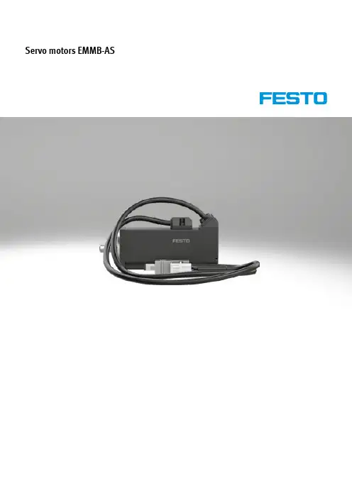
Servo motors EMMB-AS2d Internet: /catalogue/...Subject to change – 2022/11Servo motors EMMB-ASKey featuresEverything from a single source Motors EMMB-ASa Page 4• Brushless, permanently excited synchronous servo motors • Reliable, dynamic, precise• Digital absolute displacement en-coder with single turn, multi-turn optional• Optimised connection technology• Winding variants– For single-phase motor controller– Optimised for rotational speed • Holding brakeGear unit EMGA-EAS/-SASa Page 10• Low-backlash planetary gear • Gear ratio i = 3 and 5, available from stock• Life-time lubrication• Degree of protection: IP54• Other gear unit types, r atios, designs and versions on request Servo drive CMMT-ASa Internet: cmm• Universal servo drive for synchronous s ervo motors • Integrated EMC filters • Integrated brake chopper • Integrated braking resistor • Integrated safety functions• Position controller • Speed controller • Force controller•Range of control functions• Interfaces:– EtherCAT – PROFINETMotor, encoder and connecting cables NEBMa Page 11• Suitable for energy chains• Connection technology on motor side with degree of protection to IP20• Can be used in a wide temperature rangeAxial and parallel kits EAMMa Internet: eamm• Specific kits for all electromechani -cal axes from Festo• Each kit includes the relevant neces-sary coupling housing, couplings and motor flange as well as all screws• Optionally with degree of protection IP65Servo motors EMMB-AS Type codes3 2022/11 – Subject to change d Internet: /catalogue/...4d Internet: /catalogue/...Subject to change – 2022/11Servo motors EMMB-ASData sheetH- -NoteMotors and motor controllers from Festo have been specially designed to be used together. Trouble-free operation cannot be guaranteed in combination with third-party controllers.52022/11 – Subject to changed Internet: /catalogue/...Servo motors EMMB-ASData sheet1)The rotary shaft seal is included in the scope of delivery of the motor.2)For information about the area of use, see the EC declaration of conformity at: /sp d Certificates.If the devices are subject to usage restrictions in residential, commercial or light-industrial environments, further measures for the reduction of the emitted interference may be necessary.6d Internet: /catalogue/...Subject to change – 2022/11Servo motors EMMB-ASData sheetPin allocation – Motor side MotorBrakeEncoder72022/11 – Subject to changed Internet: /catalogue/...Servo motors EMMB-ASData sheetTorque M as a function of rotational speed n Flange size 40Flange size 60Performance class 01Performance class 02Flange size 60Flange size 80Performance class 04Performance class 07Peak torque Nominal torqueH- -NoteTypical motor characteristic curve with nominal voltage and optimal motor controller.Servo motors EMMB-ASData sheet8d Internet: /catalogue/...Subject to change – 2022/1192022/11 – Subject to changed Internet: /catalogue/...Servo motors EMMB-ASData sheetServo motors EMMB-ASData sheet10d Internet: /catalogue/...Subject to change – 2022/11112022/11 – Subject to changed Internet: /catalogue/...Servo motors EMMB-ASAccessories1)The battery is not included in the scope of deliveryServo motors EMMB-ASAccessories12d Internet: /catalogue/...Subject to change – 2022/11。
M700驱动菲仕永磁同步电机参数调试
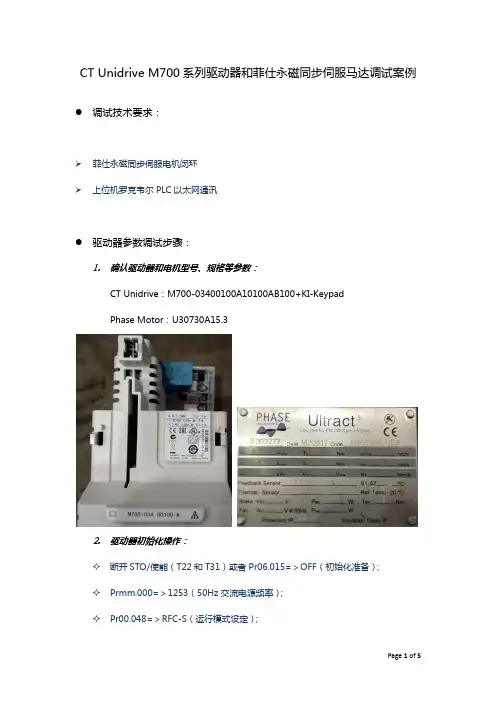
CT Unidrive M700系列驱动器和菲仕永磁同步伺服马达调试案例●调试技术要求:➢菲仕永磁同步伺服电机闭环➢上位机罗克韦尔PLC以太网通讯●驱动器参数调试步骤:1.确认驱动器和电机型号、规格等参数:CT Unidrive:M700-03400100A10100AB100+KI-KeypadPhase Motor:U30730A15.32.驱动器初始化操作:✧断开STO/使能(T22和T31)或者Pr06.015=>OFF(初始化准备);✧Prmm.000=>1253(50Hz交流电源频率);✧Pr00.048=>RFC-S(运行模式设定);✧按下红色复位按键(初始化完成)。
✧接通STO/使能(T22和T31)或者Pr06.015=>ON(驱动器使能待机)3.更改用户安全级别/访问级别:✧Pr00.049=>1(所有菜单均允许编辑)4.编码器相关接线和参数设定:✧菲仕电机编码器为绝对型,和CT驱动器完美兼容,接线图如下图所示:✧Pr03.024=>0(RFC反馈模式:Feedback);✧Pr03.026=>0(电机控制反馈选择:P1 Drive);✧Pr03.034=>2500(P1每转旋转脉冲数:2500PPR);✧Pr03.036=>0(P1电源电压:5V);✧Pr03.038=>3(P1设备类型:AB Servo);✧Pr03.039=>1(P1终端选择:AB启用,Z不启用);✧Pr03.118=>1(P1热敏电阻类型:KTY84)。
5.电机参数设定和参数自调谐:✧Pr05.007=>7.4(额定电流:7.4A);✧Pr05.008=>1500(额定转速:1500RPM);✧Pr05.009=>362(额定转速:1500RPM);✧Pr05.011=>8(电机极数:8Poles);✧Pr05.033=>224(每1000转电压:224V/1000RPM);✧Pr05.012=>2(电机自调谐方式:ROTATING,※电机旋转自调谐务必保证电机光轴,无负载输出);✧Pr01.014=>4(给定选择器:Keypad);✧按下键盘绿色运行按键,键盘显示Auto Tune,电机旋转自调谐,如果自调谐成功完成,键盘显示Inhibit。
伺服电机 说明书
第六章............................................................................................... 61
错误报警及处理 ................................................................................................ 61 6.1 报警一览表 .............................................................................................. 61 6.2 报警处理方法 .......................................................................................... 62
第七章............................................................................................... 65
通电运行 ............................................................................................................ 65 7.1 电源连接 .................................................................................................. 65 7.2 试运行 ...................................................................................................... 67 7.3 调整 .......................................................................................................... 69
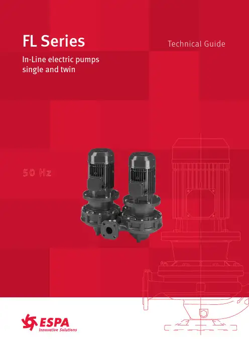
FL Series电动泵商品技术指南说明书
Sectors of application ...............................................................................................................................................................4Technical characteristics FL .................................................................................................................................................5-6Technical characteristics FLD ..............................................................................................................................................7-8Electropump identification data and nominal dat a ..........................................................................................................9List of models and table of materials ...........................................................................................................................10-17Mechanical closing device in accordance with the EN 12756 standard (18)List of models .............................................................................................................................................................................19Motor specifications and electrical data .....................................................................................................................20-22Electropump FLH-FLDH .....................................................................................................................................................23-24Hydraulic performance field and table, 50 Hz 2-poles at 2900 rpm ...................................................................25-26Hydraulic performance field and table, 4 -poles at 1450 rpm ..............................................................................27-30Hydraulic performance field and table (single operation), 2-poles at 2900 rpm ............................................31-32Hydraulic performance field and table (parallel operation), 2-poles at 2900 rpm .........................................33-34Hydraulic performance field and table, (single operation), 4 -poles at 1450 rpm .........................................35-36Hydraulic performance field and table, (parallel operation), 4 -poles at 1450 rpm .......................................37-38Hydraulic performance field and table, (single operation and parallel), 4 -poles at 1450 rpm ................39-40Operating characteristics FL -FLS, 50 Hz 2-poles at 2900 rpm .............................................................................42-51Operating characteristics FL -FLS, 50 Hz 4 -poles at 1450 rpm ............................................................................52-67Operating characteristics FLD -FLSD, 50 Hz 2-poles at 2900 rpm .......................................................................68-77Operating characteristics FLD -FLSD, 50 Hz 4 -poles at 1450 rpm ......................................................................78-92Dimensions, weights and accessories .......................................................................................................................94-117Notes (118)FL Series FL Series t IndexIn-line single and twin centrifugal electric pumps with dry-rotor The FL pump is a centrifugal pump with a single impellor and aspiration and impulsion orifices clamped in-line.Market sectors: Civil, industry.>> Water circulation in heating and air conditioning systems>> Handling of water and clean, chemically non-aggressive liquids.Field of application t FL at 2900 rpm and 1450 rpmCurves obtained in accordance with ISO9906 appendix A.Specificationst The FL is a centrifugal pump with a single impellor and aspira-tion and impulsion orifices clamped in-line.Technical datat Delivery up to 190 m3/h. 2 poles. 330 m3/h for 4 poles.t Head up to 89 m. 2 poles. 35 m for 4 poles.t Temperature of pumped liquid:-10 ÷ 130 °C for the “E” version,-20 ÷ 140 °C for the “S” version (depending on working pressure).t Maximum working pressure:10 bar (PN10) for the “E” version, 16 bar (PN 16) for the “S” version up to 120°C, 13 bar from 120°C and 140°C.t Impeller made of AISI 316L stainless steel, laser technology welded, up to size 80-160. Cast iron impeller for bigger sizes. Bronze impeller available on request for FLD 80-200 and bigger, in both the “E” and “S” versions.t Wear rings made of AISI 316L stainless steel, up to FL 100, on the impeller’s front and rear wear plates, to ensure high performance and easy replacement.t Mechanical seal according to EN 12756 (ex DIN 24960), lubricated by internal recirculation of pumped liquid to seal housing (up to FL 100).Mechanical seal locking pin slot on models up to FL 100 (on request.t Air valve on models up to FL 100.t Counterflange kits available on request.Electrical and motor specificationst Three-phase asynchronous, squirrel cage rotor, enclosed cons-truction, external ventilation.t IP55 protection.t Class F insulation.t Performances according to EN 60034-1.t Maximum ambient temperature: 40°C.t Continuous dutyt Standard voltage:Single-phase version 220-240 V 50 Hz, with built-in automatic reset overload protection up to 1,5 kW.For higher powers the protection to be provided by the user. Three-phase version 230-400 V 50 Hz for powers up to 4 kW; 400-690 V 50 Hz for powers above 4 kW.Overload protection to be provided by the user.t The ESPA surface motors have efficiency values that fall withinthe range normally referred to as efficiency class 2.Construction featurest Single-impeller centrifugal pump with in-line suction and delivery flanges.t Flanges in compliance with UNI EN 1092-2 (ex UNI 2236) and DIN 2532.t Back pull-out design (impeller, adapter and motor can be extracted without disconnecting the pump body from the pipes).FL series characteristicst Pump coupling: close-coupled by means of an adapter, with impeller keyed directly to the motor shaft extension.t Maximum operating pressure: 10 bar (PN 10)t Temperature of pumped liquid: -10ºC to 130°C.FLS series characteristicst Pump coupling: by adapter, with bracket and rigid coupling keyed to the shaft extension of standard motor.t Maximum operating pressure: 16 bar (PN 16) up to 120°Cto 140°C.t Temperature of pumped liquid: -20°C to 140°C.FL..H series characteristicst Variable speed control, using the Hydrovar® (on request), is recommended for managing pump operation according to system conditions. This ensures energy savings, lower operating costs, greater comfort and environmental protection. t This option is available for both the FL and FLS series, and includes the Hydrovar® (on request) and sensors. Accessories on requestt Threaded steel or galvanized iron counterflanges.t Pump supportOptional featurest Different voltages and frequencies.t Different materials for the mechanical seal and pump body seal. t Support available for vertical mounting (where added).t Motors Eff.1 (for FLS series).Installationt Installed in horizontal or vertical piping, in any position except with motor or terminal box facing downward.t Motor powers 5.5 kW and higher, for installations with motor shaft in the vertical position, the electric pump should be mounted on a base, the pump should rest on its feet or on the support foot (optional accessory). For installations with motor shaft in the horizontal position, use a support foot for the motor.FL - FL4 40-100 FLS - FLS4 40-100 FLS4 125-150Specificationst The FLD pump is a twin centrifugal pump with a single impellor and aspiration and impulsion orifices clamped in-line. Technical datat Delivery with one pump running: up to 190 m3/h with 2 poles motor, up to 330 m3/h with 4 poles motor; with two pumps running: up to 350 m3/h with 2 poles motor, up to 610 m3/h with 4 poles motor.t Head up to 89 m with 2 poles motor, up to 35 m with 4 poles motor.t Temperature of pumped liquid:-10 ÷ 130 °C for the “E” version,-20 ÷ 140 °C for the “S” version (depending on working pressure).t Maximum working pressure:10 bar (PN10) for the “E” version,16 bar (PN 16) for the “S” version up to 120°C, 13 bar from 120°C and 140°C.t Impeller: made of AISI 316L stainless steel, laser technology welded, up to size 80-160. Cast iron impeller for bigger sizes. Bronze impeller available on request for FLD 80-200 and bigger, in both the “E” and “S” versions.t Wear rings made of AISI 316L stainless steel, up to FL 100, on the impeller’s front and rear wear plates, to ensure high performance and easy replacement.t Mechanical seal according to EN 12756 (ex DIN 24960), lubricated by internal recirculation of pumped liquid to seal housing (up to FL 100) (on request).t Air valve on models up to FL 100.t Counterflange kit available on request.Electrical and motor specificationst Three-phase asynchronous, squirrel cage rotor, enclosed cons-truction, external ventilation.t Protection class IP55.t Class F insulation.t Performances according to EN 60034-1.t Maximum ambient temperature: 40°C.t Continuous duty.t Standard voltage:Single-phase version 220-240 V 50 Hz, with built-in automatic reset overload protection up to 1,5 kW. For higher powers the protection to be provided by the user.Three-phase version 230/400 V 50 Hz for powers up to 4 kW, 400/690 V 50 Hz for powers above 4 kW. Overload protection to be provided by the user.t The ESPA surface motors have efficiency values that fall withinthe range normally referred to as efficiency class 2.Construction featurest Two single-impeller centrifugal pumps featuring in-line suction and delivery flanges, with automatic changeover valve.t The two pumps can operate separately or in parallel.t Flanges in compliance with UNI EN 1092-2 (ex UNI 2236) and DIN 2532.t Back pull-out design; (impeller, adapter and motor can be extracted without disconnecting the pump body from the pipes). FLD series characteristicst Pump coupling: close-coupled by means of an adapter, with impeller keyed directly to the motor shaft extension.t Maximum operating pressure: 10 bar (PN 10)t Temperature of pumped liquid: -10ºC to 130°C.FLSD series characteristicst Pump coupling; by adapter, with bracket and rigid coupling keyed to the shaft extension of standard motors.t Maximum operating pressure: 16 bar (PN 16) up to 120°C,13 bar from 120°C to 140°C.t Temperature of pumped liquid: -20ºC to 140°C.FLD..H series characteristicst Variable speed control, using the Hydrovar®, is recommended for managing pump operation according to system conditions. This ensures energy savings, lower operating costs, greater comfort and environmental protection.t This option is available for both the FLD and FLSD series, and includes the Hydrovar® and sensors.Accessories on requestt Threaded steel or galvanized iron counterflanges.t Stand.Optional featurest Different voltages and frequencies.t Different materials for the mechanical seal and pump body seal. t Stand available for vertical mounting.t Version with frequency converter (variable speed).t Motors Eff. 1 (for FLSD series).Installationt Can be installed on horizontal or vertical piping, in any position except with motor or terminal board facing downward.t With motor powers 5.5. kW and up, for installations with motor shaft in the vertical position, the electric pump should be mounted on a base, the pump should rest on its feet or on the support foot (optional accessory). For installations with motor shaft in the horizontal position, use a support for the motor.FLD - FLD4 40-100 FLSD - FLSD4 40-100 FLSD4 125-150FL SeriesFL Series t Electropump identification data and nominal dataNominal dataFL/FLD series identification code FL/FLD B 4020040-/6AH 4 E = Close-coupled version S = Version with rigid coupling, IEC standard motorFL/FLD Series nameNull = Version with steel or cast iron impeller depending on size B = Version with bronze impellerVersion with HydrovarNull = 2 poles motor 4 = 4 poles motorNull = Three-phase version M = Single-phase versionDelivery port nominal diameter (mm)Impeller nominal diameter (mm)Rated motor power (kW x 10)Null = 50 Hz 6 = 60 HzReduced impellerFL Series FL Series t List of models and table of materialsFL - FL4 seriesVERSION 2 POLESVERSION 4 POLES * For 40/50-125 2/4 poles, 40/50-160 2/4 poles versionsFL4 seriesFLS - FLS4 seriesVERSION 2 POLES VERSION 4 POLESFLS4 seriesFLD - FLD4 seriesVERSION 2 POLES VERSION 4 POLESFLD4 seriesFLSD - FLSD4 seriesVERSION 2 POLES VERSION 4 POLESFLSD4 seriesFL SeriesFL Series t Mechanical closing device in accordance with the EN 12756 standardFL/FLD 40 ÷ 100FL/FLD 125 ÷ 150FL-FLD mechanical seal, according to EN 12756t Mechanical seal mounting dimensions according to EN 12756 (ex DIN 24960) and ISO 3069. (A version with anti-rotation lockpin is available on request).Pressure/Temperature application limits for complete pump (with any of the seals listed above)FL SeriesFL Series t List of models2 Poles4 Poles• Available• AvailableFL SeriesFL Series t Motor specifications and electrical dataMotort Squirrel cage motor in short circuit (TEFC), aluminium casing, enclosed construction with external ventilation. The standard supply features motors for powers up to 7.5 kW (included) in the 4 poles version, and up to 22 kW (included) in the 2 poles version. Other motor brands are used for higher powers.t The Espa surface motors have efficiency values that fall within the range normally referred to as efficiency class 2.t Cooling is ensured by a fan according to EN 60034-6.t The terminal bus is made of aluminium alloy.t The cable gland has standard passage dimensions according to EN 50262 (metric size).t The standard protection is IP 55, insulation class F.t Standard voltage:Single-phase version: 220-240 V 50 Hz, with incorporated automatic-reset overload protection up to 1,5 kW.Three-phase version: 230/400 V 50 Hz for powers up to 4 kW. 400/690 V 50 Hz for powers above 4 kW.Overload protection to be provided by the user.FL, FLD series. Single-phase 50 Hz, 2 poles motorsFL, FLD series. Three-phase 50 Hz, 2 poles motorsFL SeriesFL Series t Motor specifications and electrical data FLS, FLSD series. Three-phase 50 Hz, 2 poles motorsFL4, FLD4 series. Three-phase 50 Hz, 4 poles motorsFL SeriesFL Series t Motor specifications and electrical dataMotor noiset The tables show the mean sound pressure (Lp) measured at 1 meter distance in free field according to the A curve (according to ISO standard 1680).t The noise values are measured with idling 50 Hz motor with a tolerance of 3 dB (A).Motor noise FL, FLS, FLD and FLSD 2 poles 50 Hz Motor noise FL4, FLS4, FLD4 and FLSD4 4 poles 50 HzSpecificationst We recommend the use of the FL-FLD series electric pumps combined with the Hydrovar®.t Hydrovar® are microprocessor controlled devices for pumping systems, designed to control pump operation according to system conditions and requirements.t This way the simple electric pump is transformed into a complete pumping system principally designed forair-conditioning and heating applications, adapting the differential pressure of the closed circuit to the requested load. No special pumps or motorst Hydrovar® is mounted directly onto a standard three-phase TEFC motor with class F insulation.t Hydrovar® enables the control of an electric circulator pump by monitoring the power control, without requiring a differential pressure transmitter.No separate control panels or converterst Hydrovar® performs all the functions of a pump control panel, incorporating protections against overload, short circuit, high temperature, etc. The only external device required is a fuse on the power supply line that will depend upon any local electrical installation regulations.No by-pass lines or safety systemst With Hydrovar® the pump switches off immediately when demand is zero or exceeds the maximum capacity of the pump. This way there is no need to install additional safety devices.t The pump’s operation at the correct speed based on system requirements enables energy consumption to be substantially reduced.General operating principles of the Hydrovar® system Array t The basic function of the Hydrovar® device is to control thepump to meet the system demands.t For the FL and FLD series electric pumps, typical operationconsists in system regulation based on the characteristic curve (B).Hydrovar® performs these functions byt Measuring the system pressure or flow via a transmittermounted on the pump’s delivery side.t Calculating the motor speed to maintain the correct flow orpressure.t Sending out a signal to the pump to start the motor, increasespeed, decrease speed or stop.t In the case of multiple pump installations, Hydrovar® willautomatically provide for the cyclic changeover of the pump’s starting sequence.Control systems operationst In addition to these basic functions, Hydrovar® can do thingsonly by the most advanced computerised control systems,such as:– Stop the pump(s) at zero demand.– Stop the pump(s) in case of water failure on the suction side (protection against dry running).– Stop the pump if the required delivery exceeds the pumps’scapacity (protection against cavitation caused by excessivedemand), or automatically switch on the next pump in a multiple series.– Protect the pump and motor from overvoltage, undervoltage, overload and earth fault.– Vary the pump speed acceleration and deceleration time.– Compensate for increased flow resistance at high flow rates. – Conduct automatic test starts at set intervals.– Monitor the converter and motor operating hours.– Display all functions on an LCD in different languages (Italian, English, French, German, Spanish, Portuguese, Dutch).– Send a signal to a remote control system which isproportional to the pressure and frequency.– Communicate with another Hydrovar or control system via an RS 485 interface.FL SeriesFL Series t Hydraulic performance field, 50 Hz 2-poles at 2900 rpmFL and FLS seriesThe declared performances are valid for liquids with density r = 1,0 kg/dm3 and kinematic viscosity u = 1 mm2/s.FL SeriesFL Series t Hydraulic performance table, 50 Hz 2-poles at 2900 rpm* FL40-200/40A: 4 (kW) - 5.5 (HP) / FLS40-200/30: 3 (kW) - 4 (HP)** FL50-250/92: 9.2 (kW) - 12.5 (HP) / FLS50-250/110A: 11 (kW) - 15 (HP)Performances according to ISO 9906 - Annex A** FL65-200/92: 9.2 (kW) - 12.5 (HP) / FLS65-200/110A: 11 (kW) - 15 (HP)Performances according to ISO 9906 - Annex AFL SeriesFL Series t Hydraulic performance field, 4 -poles at 1450 rpmFL4 and FLS4 seriesThe declared performances are valid for liquids with density r = 1,0 kg/dm3 and kinematic viscosity u = 1 mm2/s.FL SeriesFL Series t Hydraulic performance table, 4 -poles at 1450 rpmFL4 and FLS4 series* FL4 version onlyPerformances according to ISO 9906 - Annex APerformances according to ISO 9906 - Annex AFL4 and FLS4 seriesFL SeriesFL Series t Hydraulic performance field, 4 -poles at 1450 rpmFLS4 seriesThe declared performances are valid for liquids with density r = 1,0 kg/dm3 and kinematic viscosity u = 1 mm2/s.FL SeriesFL Series t Hydraulic performance table, 4 -poles at 1450 rpmFLS4 seriesPerformances according to ISO 9906 - Annex AFL SeriesFL Series t Hydraulic performance field (single operation), 2-poles at 2900 rpm FLD and FLSD seriesThe declared performances are valid for liquids with density r = 1,0 kg/dm3 and kinematic viscosity u = 1 mm2/s.FLD and FLSD series* FLD40-200/40A: 4 (kW) - 5.5 (HP) / FLSD40-200/30: 3 (kW) - 4 (HP)** FLD50-250/92: 9.2 (kW) - 12.5 (HP) / FLSD50-250/110A: 11 (kW) - 15 (HP) Performances according to ISO 9906 - Annex AFLD and FLSD series** FLD65-200/92: 9.2 (kW) - 12.5 (HP) / FLSD65-200/110A: 11 (kW) - 15 (HP) Performances according to ISO 9906 - Annex AFLD and FLSD seriesThe declared performances are valid for liquids with density r = 1,0 kg/dm3 and kinematic viscosity u = 1 mm2/s.FL SeriesFL Series t Hydraulic performance table (parallel operation), 2-poles at 2900 rpmFLD and FLSD series** FLD65-200/92: 9.2 (kW) - 12.5 (HP) / FLSD65-200/110A: 11 (kW) - 15 (HP)Performances according to ISO 9906 - Annex AFLD and FLSD series* FLD40-200/40A: 4 (kW) - 5.5 (HP) / FLSD40-200/30: 3 (kW) - 4 (HP)** FLD50-250/92: 9.2 (kW) - 12.5 (HP) / FLSD50-250/110A: 11 (kW) - 15 (HP)Performances according to ISO 9906 - Annex AFL SeriesFL Series t Hydraulic performance field, (single operation), 4 -poles at 1450 rpm FLD4 and FLSD4 seriesThe declared performances are valid for liquids with density r = 1,0 kg/dm3 and kinematic viscosity u = 1 mm2/s.FLD4 and FLSD4 series* FLD4 version onlyPerformances according to ISO 9906 - Annex A FLD4 and FLSD4 series* FLD4 version onlyPerformances according to ISO 9906 - Annex AFLD4 and FLSD4 seriesThe declared performances are valid for liquids with density r = 1,0 kg/dm3 and kinematic viscosity u = 1 mm2/s.FL SeriesFL Series t Hydraulic performance table, (parallel operation), 4 -poles at 1450 rpmFLD4 and FLSD4 series* FLD4 version onlyPerformances according to ISO 9906 - Annex AFLD4 and FLSD4 series* FLD4 version onlyPerformances according to ISO 9906 - Annex AFL SeriesFL Series t Hydraulic performance field, (single operation and parallel), 4 -poles at 1450 rpmFLSD4 series (single operation)FLSD4 series (parallel operation)The declared performances are valid for liquids with density r = 1,0 kg/dm 3 and kinematic viscosity u = 1 mm 2/s.The declared performances are valid for liquids with density r = 1,0 kg/dm 3 and kinematic viscosity u = 1 mm 2/s.FL SeriesFL Series t Hydraulic performance table, (single operation and parallel), 4 -poles at 1450 rpmFLSD4 series (single operation)Performances according to ISO 9906 - Annex AFLSD4 series (parallel operation)Performances according to ISO 9906 - Annex AFL SeriesFL Series t Operating characteristics FL -FLS, 50 Hz 2-poles at 2900 rpm FL and FLS series 40 - 125/160FL and FLS series 40 - 200/250FL and FLS series 50 - 125/160FL and FLS series 50 - 200/250FL and FLS series 65 - 125/160FL and FLS series 65 - 200/250FL and FLS series 80 - 125/160FL and FLS series 80 - 200FL and FLS series 100 - 160。
biffi f02
3.2.3.1 室内存储 除 3.2.2.1 说明外,还有: - 如执行机构是标准塑料帽封堵,则应更换为防水帽。 - 连接件 (如法兰等) 必须涂上保护油或油脂 (如果可能用保护板保护) - 如果 F02 随机提供了碱性电池,则应拆下电池,存放在干燥洁净的地方
IP66/IP68 根据 NEMA ICS6/NEMA250 标准,NEMA 4/4X/6
1.5.1.1 防水防尘型铭牌 铭牌描述如下:
1.5.2 隔爆型 适合于在危险区域安装的 F02 是按照 EN50014, 50018, 50019, 50020, EN50281-1-1 标准设
计和制造的。 根据现场要求,还可以提供不同类型的防护。 没有根据 ATEX 94/9EC 和 EN13463-1, 13463-5 不正确安装阀门或相应的配套减速齿轮也会
F02 角行程电动执行机构
安装及维护手册
2.6 可选模块 F02 系列执行机构可以附加几种可选模块,如下表所列。请参考下表进行功能组合。
OM1
P1
OM1
P5
OM1
P8
OM1
PC
OM1
P9
OM1
PA
OM1
P6
OM1
P7
OM2
P2
OM3
P3
OM3
PJ
OM3
PD
OM3
PF
OM4
P4
OM8
3A
OM8
4A
OM8
5A
OM8
6A
OM9
3P
OM9
4P
OM9
5P
OM9
6P
OM10
3F
OM10
Festo 电机驱动器操作手册说明书
原版操作手册的译本© 2020 Festo SE & Co. KG 保留一切权利1适用文件有关产品的所有文件 è/sp 产品的用户文件使用手册EMCA-EC-DIO-…设备及功能说明书;装配、安装、调试和诊断使用手册EMCA-EC-C-HP-…设备配置文件 FHPP (Festo Handling and Positioning Profile)的说明FCT 插件帮助EMCAFesto Configuration Tool (FCT) 的在线帮助,用于调试和参数设置专项文件EMCA-EC_UL-…根据 Underwriters Laboratories Inc. (UL) 认证在美国和加拿大使用本产品的要求Tab. 12安全–务必注意遵守产品相关文件和其它所用部件文件中的安全和警告注意事项。
–进行装配和安装工作之前,关闭供电电压并采取保护措施,防止其意外重新启动。
在彻底完成装配和安装工作之后,才能重新接通电源。
–禁止在带电情况下插拔插头。
–遵守有关静电敏感部件的操作规程。
–只有当正确安装驱动器并完成全部参数配置之后,才能启用控制器。
–不允许对本设备进行维修。
若损坏,则更换设备。
–除了外壳盖上的 4 颗螺钉,不得松开其他螺钉。
触碰炙热表面有烫伤危险。
接触壳体可能导致烫伤。
由此可能造成人员惊慌,并作出失控反应。
这还可能造成其他损失。
•避免意外触碰壳体。
•告知操作人员和维护人员可能存在的危险。
•进行维修工作之前:使驱动器冷却到 40 °C 以下。
快速旋转的电机轴具有较高的扭矩。
接触电机轴,可能会造成烫伤和擦伤。
•确保不会接触到旋转的电机轴和其上安装的部件。
产生气体,存在火灾危险。
清洁剂与驱动器的高温表面发生接触,可能会产生气体并着火。
•进行清洁工作之前,使驱动器冷却到室温。
2.1按规定使用按照规定,本产品用于驱动和控制机电驱动器。
本产品设计用于安装在机器中。
仅允许在以下情况下使用:–在技术性能完好的状态下–在未作擅自修改的初始状态下;仅允许使用产品随附文件中的扩展–在本产品技术参数规定的极限值内–在工业领域内除工业环境外,例如在商业和住宅混合区等,必须采取措施防止无线电干扰。
宁波菲仕交流全数字伺服电机操作
AX-V 全数字交流伺服驱动器用户手册宁波菲仕电机技术有限公司版本号:AXV-SPDV-1-0序言感谢您购买宁波菲仕电机技术有限公司的菲仕AX-V全数字交流伺服驱动器(以下简称驱动器)产品。
AX-V系列伺服驱动器是针对交流永磁伺服电机控制用的高品质、多功能、低噪音的伺服驱动器,可对伺服电机实现速度、力矩和位置高精度、高响应的控制。
AX-V系列伺服驱动器为您提供了丰富而又强大的功能:✧可以通过RS-485、CanOpen总线、ProfiBus总线与上位控制器通信,驱动器的所有参数和指令均可以通过上位控制器以通信的方式传送给驱动器。
✧通过Intradrive总线可以使驱动器与驱动器之间实现高速的通信,在需要多个驱动器联动的场合更具有优越性。
✧可以适配多种编码器,具体的有正余弦编码器、光电增量式编码器、旋转变压器、绝对值式编码器等,并都能使电机获得相当的控制性能。
✧AX-V系列驱动器具有可编程功能,允许用户对伺服驱动器进行程序开发,并且有8个数字量输入点、8个数字量输出点、3个模拟量输入口、4个模拟量输出口供用户编程使用,具有很大的灵活性。
而且,用户可以根据实际工作场合要求开发适合于自己使用的应用工程软件。
✧我公司为用户提供了速度、位置控制标准应用工程软件,可以满足大多数控制场合的使用要求。
在使用AX-V系列驱动器之前,请仔细阅读本手册,以保证正确使用。
错误的操作和使用可能造成驱动器运行不正常、发生故障或者降低使用寿命,并有可能造成驱动器损坏、人身伤害等事故。
因此使用前应反复阅读本手册,并严格按照操作说明使用。
本手册为驱动器的随机附件,务必请您使用后妥善保管,以备今后对驱动器进行检修和维护时使用。
第一章注意事项1.1 开箱检查......................................P3 1.2 驱动器的型号说明..............................P3 1.3 安全注意事项..................................P3 1.3.1 安装注意事项................................P4 1.3.2 接线注意事项................................P4 1.3.3 维护注意事项................................P5 1.3.4 使用注意事项................................P5 1.3.5 报废时注意事项..............................P51.1 开箱检查在开箱时,请认真确认下列各项:在运输途中是否有破损现象驱动器型号是否与您的订货要求相一致附件是否齐全,包装箱内装有如下器件:●驱动器一台●驱动器接线端子排三个●25芯编码器插头一个●用户手册一套如发现有不符合或者遗漏的情况,请立即与我公司联系!1.2驱动器的型号说明AX-V1.3安全注意事项危险:如果没有按照要求进行操作,可能会造成设备的严重损坏或者人员的伤害。
Festo伺服压机相关产品操作手册说明书
原版操作手册的译本CANopen ®, EtherNet/IP ®, MODBUS ®, PI PROFIBUS PROFINET ® 是商标持有人在相关国家注册的商标。
.1关于本文件Tab. 1 伺服压机适用文件其它文件名称,型号目录在线帮助 YJKP 伺服压力机套件 YJKP 的软件操作应用注意事项关于连接和调试的应用范例è /spTab. 2 伺服压机的其它文件在单独的文件中说明压机各组件的应用范围及认证è /sp 。
2安全2.1按规定使用本产品是用于执行接合任务的组件,带监控接合过程的功能。
组件可在带上级控制器的机器或自动技术设备内部使用。
只能在下列条件下使用本产品:–在技术性能完好的状态下–在原版状态下使用,不得擅自改动–在本产品技术数据定义的极限值内使用–在工业领域内–牢固安装2.2可预见的错误使用禁止在下列条件下使用本产品:–擅自对产品进行更改或改装–超出负载极限值–安装位置不符合要求2.3专业人员的资质仅允许由具备资质的专业人员安装、调试、保养和拆卸本产品。
专业人员必须掌握机电一体化系统安装的专业知识。
3详细信息–附件 è /catalogue 。
–备件 è /spareparts 。
4服务若有技术问题,请联系 Festo 公司在您所在地的联系人 è 。
5产品概览1伺服电机 EMMS-AS2轴向/平行组件 EAMM-A/U 3电缸 ESBF-BS4传感器 SKDA-...-AB5连接电缆 NEBU-M12G5-E-...-LE3 6编码器电缆 NEBM7电机电缆 NEBM8LAN 电缆(不在供货范围内)9连接电缆NEBC-S1WA9-P-1.5-N-BB-L2G4 10控制器 CECC-X-M1-YS 11存储卡12电机控制器 CMMP-AS13连接电缆NEBC-S1G25-P-1.5-N-LE614上级控制器(不在供货范围内)15笔记本电脑(不在供货范围内)Fig. 1 6运输6.1运输和拆包的流程不当运输会损坏本产品。
菲仕伺服电机使用说明书(第二版)
宁波菲仕运动控制技术有限公司宁波菲仕电机技术有限公司永磁交流伺服电机Ultract III(第二版)使用说明书目录一、概述 (3)二、规范说明 (3)三、检查 (3)四、安装 (4)五、编码器配置 (4)六、接线 (6)七、PHASE电机与驱动器接线 (10)Ⅰ、匹配PHASE驱动器接线 (10)(1)、配置正余弦编码器接线 (10)(2)、配置绝对值编码器接线 (11)(3)、配置旋转变压器接线 (12)Ⅱ、匹配LENZE驱动器接线 (13)(1)、配置旋转变压器接线 (13)(2)、配置绝对值编码器接线 (14)(3)、配置数字增量式编码器接线 (15)Ⅲ、匹配KEB驱动器接线 (16)(1)、配置正余弦编码器接线 (16)(2)、配置旋转变压器接线 (17)(3)、配置绝对值编码器接线 (18)Ⅳ、匹配SIEMENS驱动器接线 (19)(1)、配置正余弦编码器接线 (19)(2)、配置旋转变压器接线 (20)Ⅴ、匹配Schneider驱动器接线 (21)(1)、配置旋转变压器接线 (21)(2/3)、配置绝对值编码器接线 (22)Ⅵ、匹配B&R驱动器接线 (24)(1)、配置绝对值编码器接线 (24)Ⅶ、匹配CT驱动器接线 (25)(1)、配置绝对值编码器接线 (25)Ⅷ、匹配Kinwaytech(御能)驱动器接线 (26)(1)、配置旋转变压器接线 (26)Ⅸ、匹配Inovance(汇川)、Modrol(蒙德)驱动器接线 (27)(1)、配置旋转变压器接线 (27)Ⅹ、匹配Vector(威科达)驱动器接线 (28)(1)、配置数字增量式编码器 (28)八、运行与维护 (29)衷心感谢您选用菲仕伺服电机,为使本电机一直维持良好的运行状态,请将本手册随整机附送给最终用户。
虽然在您的选型过程中,可能已经对本产品有所了解并与本公司的技术人员进行了某些沟通,但为充分发挥本电机最佳功能,仍请在使用前,仔细阅读本使用说明书,必要时请与PHASE的有关人员联系,获得必要的帮助,以便正确的使用和维护电机,使之运行可靠,经久耐用。
Festo EMMS-AS-100-M 电机使用说明书
Servomotore EMMS-AS-100-M…Istruzioni d'uso80386721407d[8038675]Originale:deEMMS-AS-100-M…italiano............................................NotaLe operazioni di montaggio e messa in servizio possono essere eseguite solo dapersonale specializzato provvisto di apposita qualifica,in conformitàalle istru-zioni d’uso.In caso di utilizzo in applicazioni rilevanti a livello di sicurezza si richiedono misu-re supplementari,in Europa,ad esempio,l'osservanza delle norme riportatenella Direttiva su macchinari CE.Il prodotto nonèadatto come parte essenzialeper la sicurezza di sistemi di comando se non vengono adottate misure supple-mentari secondo i requisiti minimi previsti dalla legge.•Attenzione,sulla targhetta dati nominalièriportato l'equipaggiamentodell'EMMS-AS.A seconda dell'ordine il motore include un freno di arresto(EMMS-…-RS B/RM B/RR B)nonchéun encoder(EMMS-…-R S…/R M…)o unresolver(EMMS-…-R R…).Le scariche elettrostatiche di contatto sul motore superiori a3,2kV possonosporadicamente causare problemi di funzionamento del motore.Elementi operativi e attacchiMotore con encoder Motore con resolver1Connettore per cavo di collega-mento:–Motore–Freno di arresto(solo con RS B/RM B)–Sensore di temperatura2Connettore per cavo di collega-mento:–Encoder3Fori per il fissaggio4Albero5Flangia motore6Nota:non sono ammessi colpimeccanici7Avvertenza superficie surriscaldata8Avvertenza tensione elettrica peri-colosa9Connettore per cavo di collega-mento:–Motore–Freno di arresto(solo con RR B)–Sensore di temperaturaaJ Connettore per cavo di collega-mento:–ResolverFig.11Funzionamento e utilizzoL'EMMS-ASèun servomotore ad eccitazione permanente,elettrodinamico,senzaspazzole.Nella predisposizione di fabbrica l'EMMS-ASèdotato di un encoder o diun resolver a seconda del codice di ordinazione.L'encoder invia dati motore,segnali su numero di giri e posizione sotto forma disegnali digitali ad un controller a monte.Il resolver invia ad un controller a monte un segnale analogico da cui tale controllerpuòrilevare le informazioni su numero di giri e posizione.Il motore deve funzionare sempre entro le proprie curve caratteristiche.L'EMMS-ASèdisponibile con le seguenti opzioni:EMMS-AS-…Opzione…-R S/R S B Encoder Single-turn per monitoraggio posizione…-R M/R M B Encoder Multi-turn per monitoraggio posizione…-R R/R R B Resolver per monitoraggio posizione…-RS B/RM B/RR B Freno di arresto…-S1Classe di protezione IP65(guarnizione anulare dell'albero)1)EMGA( Accessor)Riduttore1)Le guarnizioni anulari radiali dell'albero sono abrasive e in genere sono soggette ad usura.Per maggioriinformazioni si rimanda al portale di supporto Festo( ).Fig.2L'uso conforme del servomotore EMMS-AS prevede l'azionamento di sistemi diposizionamento.Il freno di arresto dell'EMMS-AS-…-RS B/RM B/RR B non fine corsaadatto per frenare il motore.2Trasporto e stoccaggio•Effettuare lo stoccaggio come indicato di seguito:–periodi di stoccaggio brevi–al fresco,all'asciutto e a prova di corrosione di raggi UV( Dati tecnici).3Condizioni di utilizzoNotaL’uso improprio puòcausare il cattivo funzionamento del prodotto.•Assicurarsi che vengano sempre osservate le prescrizioni riportate nel presen-te capitolo.•Confrontare i valori limite indicati nelle presenti istruzioni d’uso(ad es.per leforze,i momenti,le masse,le velocità,le temperature)con il caso di impiegospecifico.Lo spostamento violento dell'albero motore puòlimitare la funzionali-tàdel freno di arresto incorporato opzionale.•Adottare misure adeguate allo scopo di assicurare il rispetto delle norme speci-fiche ad es.dell'associazione di categoria o di istituti nazionali concernenti illuogo di impiego.•Utilizzare l'EMMS-AS nello stato originale,senza apportare modifiche nonautorizzate.•Tenere conto delle condizioni ambientali presenti nel luogo di installazione( Dati tecnici).4MontaggioAvvertenzaLa presenza di estremitàdi cavi scollegate con il motore in funzione puògenerare alte tensioni con pericolo di morte.1.In un primo momento il motore non deve essere accoppiato al meccanismo diavviamento.2.Accertarsi che il Controller sia senza tensione.Nonèsufficiente bloccare il segnale di abilitazione del controller.3.Cablare completamente l'EMMS-AS con il controller secondo le seguenti tabelle.L'impiego di sezioni adeguate e la schermatura dei cavi del motore/dell'enco-der/del resolver con contatto a massa bilaterale sono caratteristiche standarddei cavi precablati Festo( Accessori).4.1Motore con encoderFig.34.2Motore con resolver4.3Installazione delle parti meccaniche 1.Pulire l'albero del motore 4.Il giunto puòingranare perfettamente sull'albero solamente se quest'ultimo èasciutto e non presenta tracce di grasso.2.Spostare il cursore o il carrello dell'attuatore del meccanismo diavviamento in una posizione sicura.3.Collegare il motore ai fori 3della flangia motore 5con il meccanismo di av-viamento.Gli accessori motore preconfezionati per gli attuatori lineari sono elencati negli accessori di Festo ( Accessori).4.Stringere le viti di fissaggio ( Istruzioni per il funzionamento e accessori motore).Accertarsi che non venga esercitata nessuna forza assiale sull'albero del motore.5Messa in servizioNotaIl motore puòmettersi in moto inaspettatamente quando si allenta il freno di arresto.•Accertarsi che gli avvolgimenti motore non siano sotto corrente prima dello sblocco del freno di arresto.•Soltantoalloraalimentareelettricamenteilfrenodiarresto.Inquestomodoil motorepotràgiraresenzalimitazioni.Ilcontrolleralimentaautomaticamenteil frenodiarrestoasecondadeltipodidispositivo.•Effettuare la messa in servizio del motore con il controller in base alle istruzioni contenute nella descrizione di quest'ultimo.6Uso e funzionamentoAvvertenzaLa presenza di parti surriscaldate dell'alloggiamento puòcausare delle ustioni.•Adottare misure preventive volte impedire l'accesso di persone e oggetti estranei nell'immediata vicinanza del motore.7Manutenzione e curaAvvertenzaGli strati di polvere possono prendere fuoco.•Pulire regolarmente l'alloggiamento del motore.8Smontaggio e riparazioneAvvertenzaLa caduta di carichi puòcausare il ferimento di persone.•Accertarsi che il carico del meccanismo di avviamento si trovi in una posizione sicura (ad esempio in un'installazione verticale deve essere nella posizione finale inferiore).•Rimuovere solo allora l'EMMS-AS dal meccanismo.Nel caso in cui sia necessaria la riparazione:•Spedire il motore a FestoUn intervento dell'assistenza Festo garantisce l'adempimento a tutti gli stan-dard di sicurezza.•Eseguire il montaggio come segue:1.Spostare il cursore o il carrello dell'attuatore del meccanismo di avviamento in una posizione sicura.2.Effettuare il montaggio dell'EMMS-AS seguendo le istruzioni riportate nel capi-tolo Installazione.9Accessori Nota•Selezionare i rispettivi accessori dal nostro catalogo ( /catalogue).10Risoluzione dei problemiGuastoEventuale causaRimedioL'albero motore non giraCarico eccessivoRidurre il carico motoreController non ancora abilitato Verificare il segnale del controller Freno di arresto attivato (solo con EMMS-AS-…-RS B /RM B /RR B )Allentare il freno di arresto L'albero motore gira nel-la direzione sbagliata o vibraErrore di cablaggioVerificare e correggere il cablaggio Parametri del regolatore erratiVerificare e correggere i paramet-ri del regolatoreFig.711Dati tecniciDati generali del motoreRSRSBRMRMB RRRRBMomento di inerzia in uscita[kgcm 2]4,7295,2854,7295,2854,705,24Peso[kg]6,907,506,907,507,147,74Carico radiale sull’albero [N]570Carico assiale sull’albero[N]150Classe di isolamento secondo EN 60034-1F Classe di misurazione secondo EN 60034-1S1Conforme alla normaIEC 60034Grado di protezione (albero motore)IP54(IP65per EMMS-AS-…-S1)Temperatura ambiente[°C]–10…+40–40…+40Umiditàmassima relativa dell'aria [%]90(senza formazione di condensa)Marchio CE (vedi dichiarazione di conformità)1)secondo la direttiva UE sulla CEMLunghezzalinea max.[m]30Tensione d'esercizio encoder [V DC]5±5%-Assorbimento di corrente encoder [mA]≤160≤190-Valori di posizione/giri encoder (18Bit)262144-Giri encoder Mult-iturn (12Bit)-4096-Tensione di ingresso resolver [V]-4,0Corrente di ingressoresolver [mA]-20Rapporto di trasformazione resolver -0,5:1Numero poli resolver -2Frequenza portante resolver [kHz]-3,4…8,0Tensione freno (+6…–10%)[V]-24-24-24Potenza freno[W]-18-18-18Coppia di tenuta del freno[Nm]-9-9-91)Per l’utilizzo all’interno delle unitàabitative bisogna eventualmente adottare misure per la sop-pressione di radiodisturbi.Dati specifici del motoreHSTensione nominale [V DC]565Corrente nominale [A]3,40Momento nominale [Nm]5,63Numero giri nominale [1/min]3400Potenza nominale [W]2000Corrente di punta [A]15,0Coppia di punta [Nm]22,1Numero di giri max.[1/min]4030Costante motore[Nm/A]1,652Resistenza degli avvolgimenti (25°C)[Ω]3,25Induttivitàdegli avvolgimenti (1kHz)[mH]12,3Informazioni sulla certificazione ULCodice categoria del prodotto PRHZ2(USA)o PRHZ8(Canada)Numero del certificato E342973Standard contemplati UL 1004,C22.2n.100-92Marchio di controllo ULFig.812Curve caratteristicheCurve caratteristiche dei motori con tensione nominale e controller idealizzato.Tensione nominale 565VHS Mmax HS MnomFig.9伺服马达EMMS-AS-100-M…操作指南80386721407d[8038675]原版:deEMMS-AS-100-M…中文..............................................注意安装与调试必须由具备相应资质的专业人员按照操作手册来实施。
- 1、下载文档前请自行甄别文档内容的完整性,平台不提供额外的编辑、内容补充、找答案等附加服务。
- 2、"仅部分预览"的文档,不可在线预览部分如存在完整性等问题,可反馈申请退款(可完整预览的文档不适用该条件!)。
- 3、如文档侵犯您的权益,请联系客服反馈,我们会尽快为您处理(人工客服工作时间:9:00-18:30)。
宁波菲仕运动控制技术有限公司宁波菲仕电机技术有限公司永磁交流伺服电机Ultract III(第二版)使用说明书目录一、概述 (3)二、规范说明 (3)三、检查 (3)四、安装 (4)五、编码器配置 (4)六、接线 (6)七、PHASE电机与驱动器接线 (10)Ⅰ、匹配PHASE驱动器接线 (10)(1)、配置正余弦编码器接线 (10)(2)、配置绝对值编码器接线 (11)(3)、配置旋转变压器接线 (12)Ⅱ、匹配LENZE驱动器接线 (13)(1)、配置旋转变压器接线 (13)(2)、配置绝对值编码器接线 (14)(3)、配置数字增量式编码器接线 (15)Ⅲ、匹配KEB驱动器接线 (16)(1)、配置正余弦编码器接线 (16)(2)、配置旋转变压器接线 (17)(3)、配置绝对值编码器接线 (18)Ⅳ、匹配SIEMENS驱动器接线 (19)(1)、配置正余弦编码器接线 (19)(2)、配置旋转变压器接线 (20)Ⅴ、匹配Schneider驱动器接线 (21)(1)、配置旋转变压器接线 (21)(2/3)、配置绝对值编码器接线 (22)Ⅵ、匹配B&R驱动器接线 (24)(1)、配置绝对值编码器接线 (24)Ⅶ、匹配CT驱动器接线 (25)(1)、配置绝对值编码器接线 (25)Ⅷ、匹配Kinwaytech(御能)驱动器接线 (26)(1)、配置旋转变压器接线 (26)Ⅸ、匹配Inovance(汇川)、Modrol(蒙德)驱动器接线 (27)(1)、配置旋转变压器接线 (27)Ⅹ、匹配Vector(威科达)驱动器接线 (28)(1)、配置数字增量式编码器 (28)八、运行与维护 (29)衷心感谢您选用菲仕伺服电机,为使本电机一直维持良好的运行状态,请将本手册随整机附送给最终用户。
虽然在您的选型过程中,可能已经对本产品有所了解并与本公司的技术人员进行了某些沟通,但为充分发挥本电机最佳功能,仍请在使用前,仔细阅读本使用说明书,必要时请与PHASE的有关人员联系,获得必要的帮助,以便正确的使用和维护电机,使之运行可靠,经久耐用。
警告!搬运电机时,应小心轻放,强烈的摔、碰、震都会严重损坏电机,严禁敲击轴伸及端部;吊运时一定要确认固定好连接装置后才能吊运。
一、概述1.U III系列永磁交流伺服电机是作为一种先进的高性能伺服执行单元,可满足于自动化工业过程运动控制的广泛需要,特别适用于直接驱动的应用场合。
2.U III系列电机具有较高的转矩/体积比和功率/体积比.同时具有低惯量,高刚性的特点.电机绕组符合H级,电机绝缘符合F级要求,特殊的高频绕组适合于长配线高频PWM波型。
3.U III系列电机广泛用于各种要求的机械上,如数控车床,航空航天,军用设备,包装机械,注塑机械,纺织机械等,具有很好的运动平稳性能可以克服机械传动装置的诸多限制,使众多的应用场合完全采用直接驱动技术。
二、规范说明EC认证声明:本声明适合72/23/CEE低压规范的EC认证。
菲仕公司在无刷电机系列产品的设计,制造和测试中,完全符合72/23/CEE低压规范,适用标准:IEC72/1 ,34/1,34//55,34/11; EN60034-1+VAR A1 +VAR A2;EN60529;EN50262;CEE73/23。
三、检查1.使用前仔细检查电机外观有无损伤,核对电机标牌数据,如额定功率、电压、电流、转速等与订货要求是否相符,配件是否齐全。
2.检查电机零部件的装配应良好,紧固件应无松动或脱落。
3.用手转动电机转轴,转动应均匀一致,无异声。
4.打开接线盒,用500伏兆欧表测量电机绕组的绝缘电阻,所测值应不低于50兆欧。
注意:检查过程中,若有疑问,应向专业人员咨询或与我公司联系。
四、安装1.电机的安装应在技术人员指导下完成。
安装场所的环境条件,应符合有关标准的规定要求。
电机周围通风良好,与其他设备留有一定的间隔,便于检查、监视和清扫。
2.对带底脚的电机,安装平面要坚固、结实,有一定的刚度,安装面应平整,若平整度差,则电机运行不平稳,并将导致轴承损坏。
如果底脚要加垫片,必须保证在电机底脚安装坚固过程中不被挤出。
3.电机允许采用联轴器、齿型带及金属带传动。
安装或拆卸随电机转动的部件(如:联轴器、法兰、皮带轮、齿轮箱等)时,必须使用专用的工具,在电机轴端有带螺纹的中心孔可以利用,禁止敲击。
采用联轴器传动时,电机轴中心线与负载机械的轴中心线应重合。
若相差太大,电机运行时产生强烈振动,会损坏电机及设备。
4.有不可避免的作用于电机的轴向力时,随电机旋转的部件应靠在轴伸轴肩上,必要时,要安装隔套。
5.带制动器的电机不能有轴向力作用于电机。
6.UIII系列电机出厂检验是采用我公司AXV驱动器进行配置执行的,若使用其他公司的驱动器,请致电我司查询。
7.UIII系列电机基座号对应的安装孔、螺纹规格表:PHASE电机基座号U3 U5 U7 U10 U13 U16电机安装孔尺寸 6 9 11 14.5 19 17.5匹配螺纹规格M5 M8 M10 M12 M16 M16五、编码器配置1.UIII系列电机使用标准反馈装置是正余弦编码器,克服了传统的旋转变压器和数字编码器的分辨率的限制.可以获得极好的低速伺服性能和均匀的旋转特性。
2.同时也可以配置绝对值编码器和旋转变压器,根据客户的要求特配数字增量式编码器和施克绝对值编码器。
表1、编码器颜色、代号和信号定义表格旋变(Tamagawa) TS2650N21E78 TS2640N321E64 (代号:R3/R4) 绝对值编码器(Sick) SRS50SRM50(代号:S3/S5/S6)Resex+ 红/白 Sin+白色Resex- 黄/白(黑/白) Sin- 褐色Sin+ 蓝 Cos+粉红色Sin- 黄 Cos-黑Cos+ 红 Data+灰Cos- 黑 Data-绿- - +Vcc红- - 0V 蓝*从正余弦编码器及绝对值编码器插座正视看代码序号a 和b(绝对值编码器没有第7号)正余弦编码器( Heidenhain) ERN1385(代号:S) 数字增量式( Tamagawa ) TS5214N530 TS5214N566 (代号:D1/D2) 绝对值编码器*( Heidenhain ) ECI1319 /EQI1331 EQN1325 (代号:M/N) A+ 6b 赤红 5Vdc Data- 1a A- 2a 黑 0V Vcc 1bB+ 3b 兰 A+ A+ 2aB- 5a 兰/黑 A- Clock+ 2b I+ 4b 绿 B+ 0V sensor 3a I- 4a 绿/黑 B- B- 3b +Vcc 1b 黄 Z+ B+ 4a 0v 5b 黄/黑 Z- 0V 4b Sin+ 7b 棕 U+ Clock- 5aSin- 1a 棕/黑 U- A- 5bCos- 2b 灰 V+ +Vcc sensor 6a Cos+ 6a 灰/黑 V- Data+ 6b 0V sensor 3a 白 W+ - - +Vcc sensor 7a 白/黑 W- - -六、接线●电机接线盒内端子布局以实物为准。
●连接电机的电源线不宜过细、过长。
电机应妥善接地。
●电机应严格按所提供的电源和编码器接线图接线。
●连接电源,驱动器与电机,使电机空转,电机的转向从轴伸端视之为顺时针(正转)。
Ⅰ接线示意图:电源接线端子:U、V、W对应蓝、红、黄;1、电机风扇接线原理图:2、U10F风冷电机接线端子示意图:3、U13F风冷电机接线端子示意图:4、U13F风冷电机接线板示意图:Ⅱ信号接线端子(PCB板):表2、信号接线端子定义(*针对PHASE驱动器来定义,配第三方驱动器时,驱动器侧Cos+与Cos-对调)PCB板针脚数字增量式( Tamagawa )正余弦编码器( Heidenhain )旋转变压器( Tamagawa )绝对值编码器(Sick)绝对值编码器(Heidenhain )1 +Vcc I+ Resex+ Data+ -2 OV I- Resex- Data- -3 V- A+ Sin+ - A+4 V+ A- Sin- - A-5 U+ B+ Cos+ - B+6 U- B- Cos- - B-7 A+ 0V - 0V 0V8 A- +Vcc - +Vcc +Vcc9 Z- Cos+* - Cos+ Clock+10 Z+ Cos-* - Cos- Clock-11 W+ Sin+ - Sin+ Data+12 W- Sin- - Sin- Data-13 B- +Vccsensor - - +Vccsensor 14 B+ 0Vsensor - - 0Vsensor15 PTC+(输出) PTC+(输出) PTC+(输出) PTC+(输出) PTC+(输出)16 PTC-(输出) PTC-(输出) PTC-(输出) PTC-(输出) PTC-(输出)17 PTC+(输入) PTC+(输入) PTC+(输入) PTC+(输入) PTC+(输入)18 PTC-(输入) PTC-(输入) PTC-(输入) PTC-(输入) PTC-(输入)Ⅲ电源航空插座:M23电源插座(额定电流≤30Arms)和M40电源插座(30Arms<额定电流≤60Arm)M23电源插座(额定电流≤30Arms) M40电源插座(30Arms<额定电流≤60Arm)Ⅳ信号航空插座(*针对PHASE驱动器来定义,配第三方驱动器时,驱动器侧Cos+与Cos-对调)电源插座针脚信号定义1 U2 V6 W3 GND4 BR+5 BR-电源插座针脚信号定义U UV VW W+ BR+- BR-GND GND航空插座针脚号数字增量式( Tamagawa)正余弦编码器(Heidenhain)旋转变压器(Tamagawa)绝对值编码器(Sick)绝对值编码器(Heidenhain)1 +Vcc A+ - Sin+ A+2 OV A- - Sin- A-3 V- I+ - Cos+ Data+4 V+ Sin- Sin- Cos- PTC+5 U+ Cos+ * Cos+ Data+ Clock+6 U- Cos- * Cos- Data- -7 A+ 0V Resex+ - 0V8 A- PTC+ KTY+ KTY+ KTY+9 Z- PTC-/KTY- KTY- KTY- KTY-10 Z+ +Vcc Resex- - +Vcc11 W+ B+ - +Vcc B+12 W- B- - 0V B-13 B- I- - PTC+ Data-14 B+ Sin+ Sin+ PTC- Clock-15 PTC+ 0V sensor - - 0V sensor16 PTC-/KTY-+Vcc sensor PTC+ - +Vccsensor17 KTY+ KTY+ PTC- - PTC-七、PHASE电机与驱动器接线表:Ⅰ 匹配PHASE驱动器接线表:(1). 配置正余弦编码器接线(Heidenhain ERN1385):①.电机采用PCB板针脚:电机PCB板针脚PHASE驱动器AXV(25芯针式插头)PHASE驱动器AXM(15芯针式插头)针脚号定义针脚号1 I+ 3 142 I- 16 93 A+ 1 74 A- 14 125 B+ 2 156 B- 15 137 0V 10 18 +Vcc 25 69 Cos+ 17 310 Cos- 5 411 Sin+ 18 212 Sin- 6 515 PTC+ 11 816 PTC- 19 1②.电机采用信号航空插座:电机信号航空插座PHASE驱动器AXV(25芯针式插头)PHASE驱动器AXM(15芯针式插头)针脚号针脚号针脚号1 A+ 1 72 A- 14 123 I+ 3 144 Sin- 6 55 Cos+ 17 36 Cos- 5 47 0V 10 18 PTC+ 11 89 PTC-/KTY- 13 110 +Vcc(5V) 25 611 B+ 2 1512 B- 15 1313 I- 16 914 Sin+ 18 215 0Vsensor - -16 +VCCsensor - - 17 KTY+ - -(2). 配置绝对值编码器接线(Heidenhain ECI1319 /EQI1331):①. 电机采用PCB板针脚:电机PCB板针脚PHASE驱动器AXV(15芯针式插头)PHASE驱动器AXM(15芯针式插头)针脚号定义针脚号11 Data+ 14 1415 PTC+ 8 89 Clock+ 3 37 0V 1 18 +Vcc 6 612 Data- 9 910 Clock- 4 414 0Vsensor - -13 +VCCsensor - -16 PTC- 1 13 A+ - -4 A- - -5 B+ - -6 B- - -②. 电机采用信号航空插座:电机信号航空插座PHASE驱动器AXV(15芯针式插头)PHASE驱动器AXM(15芯针式插头)针脚号定义针脚号3 Data+ 14 144 PTC+ 8 85 Clock+ 3 37 0V 1 110 +Vcc 6 613 Data- 9 914 Clock- 4 415 0Vsensor - -16 +VCCsensor - - 17 PTC- 1 11 A+ - -2 A- - -11 B+ - -12 B- - -(3). 配置旋转变压器接线(Tamagawa TS2640N321E64):①. 电机采用PCB板针脚:电机PCB板针脚PHASE驱动器AXV(25芯针式插头)PHASE驱动器AXM(15芯针式插头)针脚号定义针脚号1 Resex+ 12 102 Resex- 24 113 Sin+ 18 24 Sin- 6 55 Cos+ 17 36 Cos- 5 415 PTC+ 11 816 PTC- 19 1②. 电机采用信号航空插座:电机信号航空插座PHASE驱动器AXV(25芯针式插头)PHASE驱动器AXM(15芯针式插头)针脚号定义针脚号4 Sin- 6 55 Cos+ 17 36 Cos- 5 47 Resex+ 12 108 KTY+ - -9 KTY- - -10 Resex- 24 11 14 Sin+ 18 216 PTC+ 11 817 PTC- 13 1Ⅱ 匹配LENZE驱动器接线表:(1). 配置旋转变压器接线(Tamagawa TS2650N21E78):①.电机采用PCB板针脚:电机PCB板针脚LENZE驱动器940(9芯针式插头)LENZE驱动器9300/9400/ECS(9芯针式插头)针脚号定义针脚号4 Sin- 7 55 Cos+ 4 66 Cos- 5 71 Resex+ 1 1- KTY83+ - 8- KTY83- - 92 Resex- 2 23 Sin+ 6 415 PTC+ 8 -16 PTC- 9 -注:电机侧KTY83位于接线端子上。