美国焊接标准
us-car焊接标准
us-car焊接标准
美国汽车行业的焊接标准主要由美国焊接协会(American Welding Society,AWS)制定和监管。
AWS发布了一系列的焊接标准,涵盖了各种不同类型的焊接方法、材料和应用领域。
其中,与汽车行业相关的焊接标准包括但不限于以下几个方面:
1. 焊接程序规范(Welding Procedure Specifications,WPS),这些规范详细描述了焊接过程中所需的所有参数和要求,包括焊接材料、电流电压、预热温度、焊接速度等,以确保焊接质量符合要求。
2. 焊接人员资格认证(Welder Qualification),针对从事汽车焊接工作的焊工,AWS制定了一系列的资格认证标准,包括对焊工技能、知识和经验的要求,以确保他们具备足够的能力和水平进行焊接工作。
3. 材料规范(Material Specifications),针对在汽车制造中使用的各种不同材料,AWS制定了相应的焊接材料规范,包括钢材、铝合金、镁合金等,以确保焊接材料的质量和可焊性。
4. 检测和评定标准(Inspection and Evaluation Standards),这些标准涵盖了焊接接头的检测方法、评定标准以及焊接质量的要求,包括X射线检测、超声波检测、磁粉检测等,以确保焊接接头的质量符合要求。
总的来说,美国汽车行业的焊接标准涵盖了从焊接工艺到焊接材料、焊接人员资格认证以及质量检测等多个方面,以确保汽车焊接工作的质量和安全性。
这些标准的制定和执行对于保障汽车制造质量、提升产品安全性具有重要意义。
astm b265焊接标准

astm b265焊接标准摘要:1.ASTM B265焊接标准简介2.焊接过程要求3.焊接材料要求4.焊接质量评估5.焊接安全措施正文:ASTM B265是一项针对焊接过程的标准,旨在规范焊接质量、焊接过程和焊接安全。
以下是根据该标准对焊接过程、焊接材料要求、焊接质量评估和安全措施的详细解读。
1.ASTM B265焊接标准简介ASTM B265是美国材料和试验协会(ASTM)制定的焊接标准之一,适用于各种焊接工艺,包括氩弧焊、电弧焊、气体保护焊等。
该标准旨在确保焊接结构的安全、可靠和耐用,适用于各种金属材料的焊接。
2.焊接过程要求根据ASTM B265标准,焊接过程应遵循以下要求:- 焊接电流:根据焊接材料和焊缝尺寸进行调整,以确保焊缝质量。
- 焊接电压:根据焊接材料和焊接电流进行调整,以保持稳定的焊接过程。
- 焊接速度:根据焊接材料、焊缝尺寸和焊接方法进行调整,以保证焊缝成形。
- 保护气:选用合适的保护气,如氩气、二氧化碳等,以防止焊缝氧化和焊渣侵入。
3.焊接材料要求焊接材料应符合以下要求:- 焊接材料的化学成分、机械性能和焊接性能应符合相关标准规定。
- 焊接材料应具有良好的可焊性、韧性和耐蚀性。
- 焊接材料应按照ASTM B265标准进行验收和储存,确保其质量稳定。
4.焊接质量评估焊接质量评估应包括以下方面:- 焊缝外观:检查焊缝成形、焊渣和焊疤等,确保符合标准要求。
- 焊缝尺寸:测量焊缝宽度、高度和长度,确保符合设计要求。
- 焊接强度:进行焊接接头拉伸试验、弯曲试验等,评估焊接强度。
- 焊接缺陷:采用无损检测方法(如超声波、X射线等)检查焊接缺陷,确保焊接结构安全。
5.焊接安全措施焊接过程应采取以下安全措施:- 佩戴个人防护装备:如防护眼镜、手套、口罩等,防止弧光、粉尘和有害气体对焊工造成伤害。
- 焊接设备维护:定期检查和维护焊接设备,确保设备安全可靠。
- 防火安全:在焊接区域设置防火设施,防止火灾事故。
焊接 厚度 坡口 标准
焊接厚度坡口标准
焊接中的坡口设计和标准通常受到相关行业的规范和标准的影响。
以下是一些关于焊接坡口的常见标准和设计原则:
1. AWS(美国焊接学会)标准:AWS D1.1/D1.1M:2020 是美国焊接学会发布的标准,主要用于结构钢的焊接。
该标准包括了有关坡口的设计和尺寸的详细规定,以确保焊接的质量和强度。
2. ASME(美国机械工程师协会)标准:ASME Boiler and Pressure Vessel Code (BPVC) 中包含了一些关于坡口设计的规范,尤其是在压力容器和锅炉的焊接中。
3. ISO(国际标准化组织)标准:ISO 9692 是国际上常用的有关焊接坡口设计的标准之一。
它提供了有关坡口几何和尺寸的指南,适用于多种材料和应用。
4. API(美国石油学会)标准:对于石油和天然气行业的焊接,API 1104 是一个常用的标准,其中包括了有关坡口的规范。
在坡口设计中,考虑以下因素是重要的:
* 坡口形状:坡口的形状可能是V 形、U 形、X 形等,具体的选择取决于应用和材料。
* 坡口尺寸:坡口的深度和宽度是根据焊接要求和材料厚度来确定的。
* 坡口角度:坡口的角度也是一个重要参数,通常以度数表示,例如45 度。
* 坡口类型:坡口可以是单坡口、双坡口等,具体取决于应用需求。
在进行任何焊接工作之前,最好遵循适用的标准和规范,以确保焊接连接的质量和强度。
同时,坡口的设计应该考虑到材料的性质、
焊接过程、应用场景等因素。
AWSD1

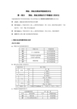
1. 非管材连接的焊接接头
1.1 评定
• 6.13.1 静荷载非管材连接的合格判据 除目检外还须进行UT的焊缝,其合格判据必须符合表6.2的要求。对于连接腹板
和翼缘板的CJP焊缝,不连续的合格与否,如采用除扫查方式“E”( 见6.30.2.2) 以外的扫查动作探测到的话,可根据实际腹板厚度加上 1 in. [25mm]得出的焊缝厚 度予以评判。而用扫查方式“E”探测到的不连续,则必须根据实际腹板厚度,用表 6.2的验收判据予以评判。当连接腹板与翼缘板的CJP焊缝承受垂直于焊缝的计算 拉应力时,此焊缝应在设计图上标明,并必须符合表6.2的要求。
D级(细小不连续) 任何这类指示,不论其在焊缝中的长度或部位,必须判定合格。
1.2 工艺
6.26.6.2 对接接头检测 所有对接焊缝必须从焊缝轴线的每一侧进行检测。角接接头和 T 型
接头焊缝基本上仅从焊缝轴线的一侧检测。所有焊缝的检测必须使用适 用的扫查方式,或在必要时使用图 6.15 所示的方式,以检测纵向和横 向不连续。这样做的意图是,只要可行,最低限度要使检测焊缝的声波 在两相交叉方向上通过所有受检测焊缝与HAZ(热影响区)的整个体积 。 6.26.6.1 扫查
孔上方(A位置),将孔回波调至基准高度(50%或80%),然 后将探头离开试块,再提高20dB,荧屏上大于12mm声程以 外,不应有超过基准高度的任何回波。
前沿 探头前沿应小于等于25mm。
分辨率 仪器控制处于正常试验状态下,将探头
分别置于RC分辨力对比试块上,使孔的反射 回波调到萤光屏中等高度。分辨能力必须至 少能区分来自三个孔的指示峰值。
-2
~
+2
astm焊接工艺评定标准

astm焊接工艺评定标准ASTM焊接工艺评定标准是指美国材料与试验协会(American Society for Testing and Materials,简称ASTM)所制定的用于评定焊接工艺的一系列标准。
这些标准旨在确保焊接工艺的可靠性和质量,以满足特定工程项目的要求。
目前,ASTM焊接工艺评定标准共有几十项,涉及不同类型的焊接方法和材料。
下面将介绍一些较为常见的ASTM焊接工艺评定标准:1. ASTM A370-19a:此标准涵盖了金属材料的力学性能测试方法,包括拉伸强度、屈服强度、断裂延伸率等。
这对于评估焊接接头的强度和可靠性非常重要。
2. ASTM A751-14:此标准规定了通过化学分析和光学显微镜检查对金属焊接接头进行质量检验的方法。
这些测试可用于检测焊接接头中的杂质、缺陷和变形等问题。
3. ASTM E1903-19:此标准规定了通过无损检测方法对焊接接头进行评估的要求。
无损检测方法主要包括超声波检测、射线检测和涡流检测等,用于监测焊接接头中的裂纹、夹杂物和疏松等缺陷。
4. ASTM E8/E8M-19b:此标准规定了金属材料的拉伸强度测试方法。
该测试方法可用于评估焊接接头的拉伸性能,以确定其是否符合设计要求。
5. ASTM E165-20:此标准规定了金属材料的硬度测试方法。
硬度测试对于评定焊接接头的力学性能以及检测焊接区域的变硬或软化非常重要。
6. ASTM E562-19:此标准规定了对焊接接头进行金相检查的方法。
通过金相检查可以观察到焊缝结构、晶粒尺寸、晶界等细节,以评估焊接接头的质量。
7. ASTM E709-15:此标准规定了对焊接接头进行射线检测的方法。
射线检测通过获取射线照片或可视化图像来评估焊接接头中的缺陷,以确保其质量符合要求。
8. ASTM A262-15:此标准规定了用于在焊接接头中检测晶界腐蚀敏感性的方法。
晶界腐蚀敏感性是焊接接头中的一个常见问题,特别是在高温环境下。
美标与国标焊接规范对比
国标、美标及欧标焊接规范对比第一部分国标、美标及欧标关于焊缝坡口的对比对建筑钢结构中常用的典型坡口形式和焊接方法SMAW/GMAW/SAW进行对比●JGJ81:2002建筑钢结构焊接技术规程●ISO 9692-1:焊接及相关工艺——推荐的焊接坡口第1 部分:钢的焊条电弧焊、气体保护焊、气焊、TIG 焊及高能束焊●ISO 9692-2:焊接及相关工艺——推荐的焊接坡口第2 部分:钢的埋弧焊●AWS D1.1/D1.1M 美国钢结构焊接规范1 焊接方法及焊透种类表示差异JGJ 81-2002:a、焊接方法及焊透种类代号代号焊接方法焊透种类MC手工电弧焊接完全焊透焊接MP 部分焊透焊接GC 气体保护电弧焊接自保护电弧焊接完全焊透焊接GP 部分焊透焊接SC埋弧焊接完全焊透焊接SP 部分焊透焊接b、接头形式及坡口形状代号接头形式坡口形状代号名称代号名称I I 形坡口B 对接接头V V 形坡口X X 形坡口U U 型坡口L 单边V 形坡口K K 形坡口T T 形接头U①U 形坡口J①单边U 形坡口C 角接头注:①—当钢板厚度≥50mm 时,可采用U 形或J 形坡口。
c、焊接面及垫板种类代号反面垫板种类焊接面代号使用材料代号焊接面规定BS 钢衬垫 1 单面焊接BF 其它材料的衬垫 2 双面焊接d、焊接位置代号焊接位置平焊横焊立焊仰焊代号 F H V O e、坡口各部分的尺寸代号代号坡口各部分的尺寸t 接缝部位的板厚(mm)b 坡口根部间隙或部件间隙(mm)H 坡口深度(mm)p 坡口钝边(mm)a 披口角度(°)f、焊缝表示方法AWS D1.1-2008:焊缝表示方法:接头类型符号-母材厚度和熔深符号焊缝类型符号-焊接方法符号2 坡口形式比较2.1 典型坡口形式全熔透焊缝差异:符合标准焊接方法 板厚 焊接位置 坡口尺寸 允许偏差 坡口示意图零件图用 装配用 JGJ 81SMAW 3~6 所有 b=t/2 0,+1.5 -3,+1.5GMAW FCAW3~8 所有 b=0~3 0,+1.5 -3,+1.5 SAW 6~12 F b=0 ±0 0,+1.5 AWS D1.1SMAW6(max ) 所有 R=T1/2 +2,-0 +2,-3 GMAW FCAW10(max ) 所有 R=0到3 +2,-0 +2,-3 SAW10(max ) F R=0 ±0 +2,-0 16(max )FR=0±0+2,-0总结 I 型坡口对接接头,背部清根,差异主要体现在偏差允许值上,AWS 所允许的偏差范围大于JGJ81。
美国通用焊接标准(FDR) AWS-ANSI 02 FDR-TWF-UNC weld specs

角焊缝尺寸(缩写为WS) 焊接件最小厚 焊缝尺寸 度(毫米) (毫米)
5 6 8 10 12
3 5 6 8 10
弹簧支架
一般焊接
一般焊接
焊接符号基于AWS(美国焊接协会标准)/ANSI(美国国家标准) A2.4-2007
一般焊接
一般焊接
焊接注释:
C-C剖视图
图纸中焊缝尺寸仅供参考。 GK焊接标准参见“CONNECTION”(焊接标准)部分。 注释A, B, C来源于“CONNECTION”(焊接)图纸。
B-B视图
一般焊接
8 10 12
6 8 10
件2完全焊接到件1 上以后焊接此处
焊接符号基于AWS(美国焊接协会标准)/ANSI(美国国家标准) A2.4-2007
一般焊接
一般焊接 一般焊接 一般焊接
一般焊接
仅限于修理工作
B-B视图
一般焊接
一般焊接
一般焊接
一般焊接
一般焊接
一般焊接
一般焊接
电机安装架装配B
NOTES A, B & C APPLY FROM "CONNECTION" DRAWINGS
SECTION C-C SCALE 1/8
TITLE
B
注释A, B, C来源于“CONNECTION”(焊接)图纸。
一般焊接 TYP.
1/4
VIEW "A-A" A-A视图
1/4
TYP 一般焊接
C-C剖视图 比例1/8
6 8 10 12
5 6 8 10
一般焊接
一般焊接
一般焊接
一般焊接
一般焊接
X详图
焊接符号基于AWS(美国焊接协会标准)/ANSI(美国国家标准) A2.4-2007
美国焊接标准

SAE-AMS-W-6858ADOPTION NOTICESAE-AMS-W-6858, "WELDING, RESISTANCE: SPOT AND SEAM", wasadopted on 05-AUG-99 for use by the Department of Defense(DoD). Proposed changes by DoD activities must be submitted tothe DoD Adopting Activity: ASC/ENOI, Building 560, 2530 Loop Road West, Wright-Patterson AFB, OH 45433-7101. Copies of this document may be purchased from the Society of AutomotiveEngineers 400 Commonwealth Drive Warrendale, Pennsylvania, United___________________States, 15096-0001. /Custodians:Adopting Activity:Army - MRAir Force - 11Navy - ASAir Force - 11AREA THJMDISTRIBUTION STATEMENT A:Approved for public release; distribution is unlimited.--`,,,,,`````,,``````,,,`,,```,-`-`,,`,,`,`,,`---SAE Technical Standards Board Rules provide that: “This report is published by SAE to advance the state of technical and engineering sciences. The use of this report is entirely voluntary, and its applicability and suitability for any particular use, including any patent infringement arising therefrom, is the sole responsibility of the user.”SAE reviews each technical report at least every five years at which time it may be reaffirmed, revised, or cancelled. SAE invites your written comments and suggestions. Copyright 2000 Society of Automotive Engineers, Inc.All rights reserved.Printed in U.S.A. QUESTIONS REGARDING THIS DOCUMENT:(724) 772-7161FAX: (724) 776-02431.2Classification:Classification is based on function and use of the welded joint, rather than certain average levels of strength. Therefore, reliability is the key underlying quality distinguishing the work for each class.The criteria described herein are intended to prevent larger variations in weld strength and quality than are compatible with the intended use.Class A A welded joint, whose failure during any operating condition would cause loss of the equipment or system or one or its major components, loss of control, unintentionalrelease or inability to release any armament score, failure of gun installationcomponents; or which may cause significant injury to occupants of manned systems.Class B A welded joint whose failure would reduce the overall strength of the equipment or system or preclude the intended functioning or use of equipment.Class C A welded joint which is considered non-critical and for which no stress analysis is considered.1.2.1The classification of welds in foil thickness is limited to Class A and Class C.2.APPLICABLE DOCUMENTS:The following documents of the issue in effect on date of invitation for bids, or request for proposal, form a part of this specification.2.1American Welding Society (AWS) Publications:Available from American Welding Society Inc., 2501 N.W. 7th Street, Miami, Florida 33125)AWS A3.0Terms and DefinitionsAWS C1.1Recommended Practices for Resistance Welding3.REQUIREMENTS:3.1Design requirements:3.1.1Definition of terms used in this specification shall be in accordance with AWS A3.0, and as shownin 6.2 herein.3.1.2The class of welding shall be designated on the item specification or drawing. The design of ClassA resistance welded joints shall require the specific approval of the procuring activity who mayapprove if satisfactory resistance welded prototypes exist, or upon evidence of the adequacy of the design and pattern of spot welding or upon the satisfactory performance of suitable static andrepeated loading testing of the design or applicable prototype.--` , , , , , ` ` ` ` ` , , ` ` ` ` ` ` , , , ` , , ` ` ` , -` -` , , ` , , ` , ` , , ` ---3.1.3There shall be two methods of certification for spot welds. The Standard Certification method shall be for a weld schedule that certifies that the requirements of Tables I through III or IV, and all other applicable weld property requirements have been met. The Design Allowable Certification method shall be a weld schedule that certifies a guaranteed strength value has been met.TABLE I. Shear strength requirements for spot weld sheet specimens--`,,,,,`````,,``````,,,`,,```,-`-`,,`,,`,`,,`---TABLE I(SI)*. Shear strength requirements for spot weld sheet specimens--`,,,,,`````,,``````,,,`,,```,-`-`,,`,,`,`,,`---TABLE II. Shear strength requirements for spot weld sheet specimens--`,,,,,`````,,``````,,,`,,```,-`-`,,`,,`,`,,`---TABLE II(SI)*. Shear strength requirements for spot weld sheet specimens--`,,,,,`````,,``````,,,`,,```,-`-`,,`,,`,`,,`---TABLE III. Shear strength requirements for spot weld sheet specimens--`,,,,,`````,,``````,,,`,,```,-`-`,,`,,`,`,,`---TABLE III(SI)*. Shear strength requirement for spot weld sheet specimens--`,,,,,`````,,``````,,,`,,```,-`-`,,`,,`,`,,`---TABLE IV. Shear strength requirements for spot welds in foilTABLE IV(SI). Shear strength requirements for spot welds in foil--`,,,,,`````,,``````,,,`,,```,-`-`,,`,,`,`,,`---3.1.3.1The Design Allowable Certification method is intended to routinely permit the design and use ofsmaller welds where the design stress permits and space or equipment or material conditionscompel; or to permit the design and use of stronger welds where they are wanted and the weld conditions are able to provide them. For a given joint a guaranteed strength value and weldclass must be specified on the drawing.--`,,,,,`````,,``````,,,`,,```,-`-`,,`,,`,`,,`---3.1.3.2The provisions of the Design Allowable Certification method may be used to certify a weldschedule when unusual conditions apply. For example, when welds are made through adhesives or through protective finishes or when it is desirable to use diffusion welds as integralreinforcements to nuggets or in lieu of nuggets.3.1.4When conditions are encountered which cause any of the requirements of this specification to beinapplicable, the contractor shall submit alternate procedures and requirements for approval by the procuring activity. The request for approval shall include a description of the conditions whichrender the requirements inapplicable, such as reduced flange widths and space limitations; and shall include data to indicate that the alternate procedures and requirements are adequate for the given application.3.1.4.1Granted approvals of alternate procedures shall remain in effect as complying with thisspecification until the contractor is notified otherwise by the procuring activity.3.2Materials and methods of preparation:3.2.1Material combinations:3.2.1.1Combinations not requiring specific approval: The metals listed below may be welded in anycombination within each lettered grouping.a.Aluminum and its alloysb.Magnesium and its alloysc.Titanium and its alloysd.Plain carbon steels of less than 0.15 percent carbone.Austenitic steels; precipitation hardening steels; nickel and cobalt base alloys.3.2.1.2Combinations requiring approval: Use of the following metals requires specific approval of theprocuring activity: Clad 7075 aluminum alloy in thicknesses less than 0.020 inch or 0.51millimeter (mm); any aluminum alloy in the 2000 or 7000 series which is unclad; or anymagnesium alloy which will be exposed to accelerating corrosion conditions like a marineenvironment.3.2.1.3Special requirements: Metal combinations not included in 3.2.1.1 shall require the followingestablishment of weld ductility. The average tensile (normal to spot plane) strength of twenty spot welded specimens shall be greater than 0.25 times the minimum average shear strength inTables I through IV applicable to the subject alloy or as established for the Design AllowableCertification. This test may be conducted on specimens, as welded, or after subsequent heattreatment. Heat treatment is a later manufacturing operation and not the post weld currentprovided through welder electrodes. The production process shall specify the certified weldschedule plus the subsequent heat treatment used to demonstrate the weld ductility requiredherein.3.2.2Surface conditions: The surface of the parts to be welded shall be free from objectionable filmssuch as heavy oxides, scale, ink, grease, dirt, or other substances or surface conditionsdetrimental to the welding process.3.2.2.1Group I materials:3.2.2.1.1Oxide coatings may be removed by mechanical treatment (such as sanding or wire brushing)or by chemical treatment.3.2.2.1.2The ability of a cleaning procedure to effectively prepare Group I materials for welding shall bedemonstrated by ability of materials cleaned by the process to be welded in compliance withthe Certification requirements of this specification. The cleaning procedure is a necessarycomponent of the Certification weld schedule.3.2.2.1.3Conformity of test and production materials surfaces to those produced by the normal cleaningprocedure shall be checked by surface resistance readings. Maximum values for test andproduction materials shall be established as indications of the conformity required for weldingin compliance with this specification.3.2.2.1.4The minimum and maximum time span that is permitted between parts cleaning and partswelding shall be established by the contractor. The contractor shall demonstrate that nodeterioration of surface conditions take place during typical holding or storage conditionsduring that span. Deterioration shall be excessive when high values lead to inability to meetCertification requirements. Conditions and limitations may be applied generally as to astandard process, or specifically as to an exceptional assembly or material combination wherewarranted.3.2.2.1.5When a cleaning procedure is changed, if the contractor can demonstrate that the newprocedure produces the same results as the old procedure, recertification of weld schedulesshall not be required. This conformity will be shown by (1) producing the same weld results asmade during Qualification tests (with Certification quantities) with a weld heat change within±10 percent of the established value and (2) showing a surface resistance average that is nomore than 1.05 times that achieved by the replaced procedure.3.2.2.1.6Coatings which improve the corrosion resistance or sealing characteristics without affecting theweld properties may be applied prior to welding. Such finishes must be considered as finalsteps of the cleaning procedure and necessary conditions specified on the Certified weldschedule.3.2.3Joint thickness: Joint thicknesses are only limited to those thicknesses or combination ofthicknesses on which Certification weld schedule can be established and production parts can be made to meet the production requirements of this specification.3.2.4Fitup: Mating parts assembled for welding shall be designed and processed to fit so that before thefirst and each successive weld is made the surfaces to be joined by the weld are in contact with each other or can be made to contact each other with manual pressure.3.3Equipment requirements:3.3.1Welding machines: The welding machine shall consist of a suitable source of electrical energy,means of adequately cooling the electrodes, and a means of reliably controlling and indicating the relative magnitude of the current, the welding force, and the time of current flow; to fulfill therequirements specified herein. The force and current controls shall operate so that no current can flow until the welding force is applied by the welding electrodes. It shall not be possible to reduce electrode force before current is terminated.3.3.2Electrodes: Suitable electrode material and shapes shall be used to perform welding inconformance with this specification.3.3.3Shear testing machines: The contractor shall provide spot weld shear testing machines asrequired. All shear testing machines shall be accurate within ±2 percent of the indicated reading.Portable spot weld shear test machines shall be checked for accuracy at intervals not to exceed 2 months.3.3.4Surface resistance indicators: The contractor shall provide one or more surface resistanceindicators for checking the effectiveness of cleaning solutions and procedures engaged inpreparing Group I metals for spot welding. Surface resistance indicators shall be checked foraccuracy and recalibrated as necessary.3.3.5Jigs and fixtures: All tooling that is required to locate welds or assist in the assembly of weldedparts that passes through the magnetic field during the molding operation, shall be made ofnonmagnetic materials insofar as possible. Jigs and fixtures must be so designed that no welding current can shunt through them instead of passing through the work pieces.3.3.6Maintenance of equipment: Unless otherwise specified, each item of equipment shall be inspectedperiodically as recommended by the manufacturer. Adequate preventative maintenance shall be furnished. Defective equipment parts affecting machine operation shall be replaced beforeproduction welding is resumed.3.4Qualification of welding machines:3.4.1Qualification approval: Qualification is performed on a distinctive resistance spot or seam weldingmachine to determine the ability and consistency of operation of a machine type at a facility.Qualification has as a purpose to identify and verify the range of welding that a facility may, forcontractual purposes, be considered capable. To have his equipment qualified and approved for use the contractor shall perform the tests specified herein under the surveillance of the procuring activity. Weld conditions shall be documented on a Machine Qualification Test Report. Typical examples of report forms are given in AWS C1.1. Such forms may be modified or expanded as required. Weld conditions and test results shall be submitted with an application for approval to the --`,,,,,`````,,``````,,,`,,```,-`-`,,`,,`,`,,`---procuring activity. After approval is indicated, these reports shall be posted near the machine so as to be available to contractor operators and inspectors, and agents of the procuring activity.3.4.1.1Qualification by one procuring activity of the Department of Defense shall be Qualification for allDOD procuring activities and for those other governmental agencies who elect to subscribe tothis specification.3.4.2Machine qualification scope: Machines shall be qualified to meet the weld requirements for thehighest classification in a metal group for which it is intended to be used in production. A machine qualified to weld to the requirements of one weld classification in a group shall be automatically considered qualified for lower weld classifications. When one machine of a distinctive type in a plant site passes the Qualification tests all other machines of the same type shall be considered qualified. Machines used for Class C foil welding are qualified just by establishing a weld schedule Certification. Machines qualified to a class for seam welding shall be considered qualified for roll spot welding to the same class.3.4.2.1Types of equipment: Distinctive types of equipment must include those differing in any of thefollowing respects:a.Manufacturer of machineb.Manufacturer of control panelc.Type of machine, or model numberd.Electrical rating or capacitye.Type of electrical energyf.Type of pressure application.3.4.2.2Test conduct: No maintenance work and no control adjustments are permitted during the weldingof a set of test specimens.3.4.2.3Test materials: The test materials for a Group I Qualification shall be any aluminum alloycommonly used in resistance welded products. For Groups 2 and 3 qualification test materialshall be any steel commonly used in resistance welded products.3.4.2.4Combination selection: For each group of alloys, two test sets shall be required. One at thehighest, one at the lowest end of the range for which the Qualification is desired. This normally means that the thickest to thickest metal combination on one end and the thinnest to thinnest on the other end.3.4.2.4.1Except that when a Qualification is achieved on one combination of foil thicknesses, theequipment shall be considered qualified for all thicker foils welded to foils.3.4.2.5Test specimen requirements: Weld test and examination requirements are shown in Table V.3.4.2.6Weld machine requalification: When the equipment has once been qualified, it need not berequalified for other contracts or production lots. A change of location within a plant, not involving a change in power source, or maintenance, or parts replacement does not necessitaterequalification. Requalification shall be required if the machine is rebuilt or if significantoperational changes are made in it. Existing machine Qualifications made under superseded revision of this specification shall be honored.3.5Weld schedule certification: 3.5.1Certification: Tests shall he conducted to determine if a particular machine, in combination with aspecific weld schedule and other specific conditions, will produce on a given set of materialsresistance welds that conform to the requirements of specification. Documentation of these tests will be contained in a completed Certification Test Report that will be available to agents of the procuring activity. In addition, the weld schedule shall be posted near the machine and beavailable to machine operators, inspectors, and agents of the procuring activity.`,,,,,`````,,``````,,,`,,```,-`-`,,`,,`,`,,`---TABLE V. Machine qualification test specimen requirements3.5.2Certification test reports: For each machine and each combination of relevant conditions (such asalloy, temper, surface conditions, and thickness combinations), the contractor will determine the effective weld machine settings for test and production parts. The schedule of conditions and parameters shall be formally entered on a report form before the test welding. Typical examples of report forms are given in AWS Cl.l. These shall be modified or expanded as required. Afteracceptance, production setups shall be made to the schedule therein given, with the scheduled latitude of 4.2.6 allowed.3.5.2.1Examination data: Part of a completed Certification test report shall be the shear strength data on each weld, the average, the numbers of specimens with shear values outside of the set limits, and the nugget diameters of each metallographic specimen. The examination page will have a formal indication of the success or failure to meet the Certification criteria applicable to thesubject material combination.--`,,,,,`````,,``````,,,`,,```,-`-`,,`,,`,`,,`---3.5.3Test vs. production conditions: It is the purpose of Certification to show the results that can beexpected on production parts. It is necessary then to produce a correspondence between testconditions and production conditions. The material conditions (3.5.2) must be replicated in parts and material for weld tests. Any other production condition known to be relevant must be part of the test. These include, for example, curvature of the parts, mandrels in lieu of electrodes, large magnetic tools lying in the weld machine throat, narrow edge distances, offset or shapedelectrodes tips, time spans (minimum and maximum) between final preparation and welding, initial and final surface preparations, and close spot spacing. A test of relevancy may be that theaverage nugget diameters in the part will equal the average Certification nugget diameters when produced by any machine weld heat seetings not further than 10 percent from the Certification heat settings.3.5.4Certification test specimen configuration and examination requirements: Tests shall be asspecified in Tables VI Through IX and as shown in Figures 1 through 6.TABLE VI. Certification specimen and examination requirements--`,,,,,`````,,``````,,,`,,```,-`-`,,`,,`,`,,`---TABLE VII. Certification specimen and examination requirements--`,,,,,`````,,``````,,,`,,```,-`-`,,`,,`,`,,`---TABLE VIII. Certification specimen and examination requirementsTABLE IX. Certification specimen and examination requirements--`,,,,,`````,,``````,,,`,,```,-`-`,,`,,`,`,,`-----`,,,,,`````,,``````,,,`,,```,-`-`,,`,,`,`,,`---FIGURE 2. Close space spot welds in sheet--`,,,,,`````,,``````,,,`,,```,-`-`,,`,,`,`,,`---FIGURE 3. Spot welds in foilFIGURE 4. Spot and seam welds in foil, peel specimen--`,,,,,`````,,``````,,,`,,```,-`-`,,`,,`,`,,`-----`,,,,,`````,,``````,,,`,,```,-`-`,,`,,`,`,,`-----`,,,,,`````,,``````,,,`,,```,-`-`,,`,,`,`,,`---FIGURE 6. Seam welds in foil, class A3.5.4.1Locate all welds in all figures within ±0.060 inch or ±1.5 mm of specimen centers. Specimendimensions are given with a tolerance of ±0.060 inch or ±1.5 mm.3.5.4.2All multiple weld specimens shall be cut and dressed for testing after radiography is completed.3.5.5 Thickness latitudes: Thickness combinations falling within the following limits shall not requireseparate certified weld schedules provided that the certified nugget size average can bereproduced with a weld heat (current) setting that lies within ±10 percent of the value established by the original Certification schedule; all other conditions being the same.(a)Foil - The variation in thickness (with regard to the original schedule) of outer sheet is within±0.001 inch (±0.03 mm) andThe variation in the summed thickness of the combination is within ±0.003 inch (±0.08 mm).(b)Sheet (outer) up to 0.040 inch (±1.02 mm), inclusive -The variation in thickness of either outer sheet is within ±0.004 inch (±0.10 mm) andThe variation in the summed thickness of the combination is within ±0.006 inch (±0.16 mm).(c)Sheet (Outer) Over 0.040 inch (1.02 mm) -The variation in thickness of either outer sheet is within ±10 percent for Group 1 alloys, or ±20percent for Groups 2 and 3 alloys andThe variation in the summed thickness of the combination is within ±10 percent.3.5.6Design allowable certification: A process weld schedule and conditions may be certified to produceany strength requirement specified on a drawing by conforming to the Design AllowableCertification requirements of this specification. This Certification method is limited to spot welds in sheet that are not close space spot welds. Examination results shall be entered on the test report.After acceptance, production setups shall be made to the schedule therein given, with the schedule latitude of 4.2.6 allowed.3.5.6.1Design allowable Certification requires the identification of the required strength, (G), on theapplicable drawing. (See 3.1.3.) The Certification report shall state "These conditions certify avalue of ____.” The number entered shall be the value of the lowest strength specimen in 300welds for Class A, 180 welds for Class B, and 50 welds for Class C. As reliability requirementswarrant, the denominator quantities (e.g., 300) may be changed by the part or systems designer through drawing notes or design specifications with the approval of the procuring activity.3.5.6.1.1Specimen requirements are given in Figure 1a or 1b. Examination requirements are given in3.6.1 for visible and 3.6.4.1.3 and 3.6.4.1.4 for mechanical criteria.--` , , , , , ` ` ` ` ` , , ` ` ` ` ` ` , , , ` , , ` ` ` , -` -` , , ` , , ` , ` , , ` ---3.5.7Recertification: An existing weld schedule need not be recertified for other contracts or designsprovided all material conditions are equal. A change of location within a plant not involving achange in power source or maintenance or parts replacement do not necessitate recertification.Recertification shall be required if the machine is rebuilt or if significant operational changes are made in it. Existing Certifications made under superseded revisions of this specification shall be honored. However, recertification of a welding schedule may be required at any time if theprocuring activity doubts for any reason the ability of a machine to make welds satisfactorily with the original Certification conditions.3.6Weld property requirements:The weld acceptance criteria for Qualification and for Certification and production conducted under the standard certification method are given under 3.6.1 for visible; 3.6.2 for radiographic; 3.6.3 for metallographic; and 3.6.4 for mechanical. For Certification and production conducted under the Design Allowable Certification weld acceptance criteria fall under 3.6.1 for visible, and 3.6.4.1.3 and3.6.4.1.4 for mechanical criteria.3.6.1Visible criteria - spot welds and seam welds:3.6.1.1Sheet separation: Separation between an inner and outer member is excessive when it exceedsa. orb., below, measured at a distance (radius) from the nugget center equal to 3 times theradius of the minimum nugget size given in Table X for the thinner member.a.Greater than 0.15 times the summed thickness of the outer sheet and the one adjacent to it,or 0.006 inch (0.15 mm), whichever is greater, orb.Greater than 0.003 inch (0.08 mm) between foil and the number adjacent to it.--` , , , , , ` ` ` ` ` , , ` ` ` ` ` ` , , , ` , , ` ` ` , -` -` , , ` , , ` , ` , , ` ---AMS-W-6858ASAE AMS-W-6858ATABLE X. Nugget size (all groups)3.6.1.1.1Excessive separation is not acceptable on specimens.3.6.1.1.2Excessive separation is not acceptable on production work if it exceeds 0.03 times the Class A or 0.10 times the Class B or C production welds sampled for examination, when the product is raised to the next whole number.3.6.1.2Surface indentation: Indentations (see Figure 7) are not acceptable if their depth exceeds the following limitations (where, t is the thickness of the indented outer member).3.6.1.2.1Excessive indentation is not acceptable on specimens.3.6.1.2.2Excessive indentation is not acceptable on production work if it exceeds 0.03 times the samples of production welds measured in Class A welds; or in more than 0.10 times the samples measured in Class B and C welds, when the product is raised to the next whole number.a.Sheet; Class A and B: 0.10 t or 0.005 inch (0.13 mm); whichever is greater.b.Sheet; Class C: 0.20 t or 0.005 inch (0.13 mm); whichever is greater.c.Foil; Class A and B: 0.30 t.d.Foil; Class C: 0.40 t.e.But when aerodynamic smoothness is a requirement, the outside indentation shall not exceed 0.004 inch (0.10 mm) on sheet and 0.20 t o on foil.3.6.1.3Production parts: Certain other imperfections are limited in quantity Table XI. The number of visible imperfections shall be calculated by multiplying the factor shown in Table XI times the number of welds inspected and raising the product to the next highest whole number. Parts or lots with imperfections exceeding the quantity as determined from Table XI shall be rejectable. Cracks open to the surface on seam welds shall be rejected and subject to a Material Review.--`,,,,,`````,,``````,,,`,,```,-`-`,,`,,`,`,,`---AMS-W-6858A SAE AMS-W-6858AFIGURE 7. Nomenclature for metallographic spot weld sections and seam weld transverse sections TABLE XI. Visible external imperfections for production parts3.6.1.4Test specimens: Qualification, Certification, and production witness test specimens shall besmooth, free of cracks, tip-pickup, pits and other flaws that indicate that the welds were madewith dirty electrodes, improperly prepared surfaces, or excessive heat and undue penetration. 3.6.2Radiographic criteria - spot welds and seem welds:。
- 1、下载文档前请自行甄别文档内容的完整性,平台不提供额外的编辑、内容补充、找答案等附加服务。
- 2、"仅部分预览"的文档,不可在线预览部分如存在完整性等问题,可反馈申请退款(可完整预览的文档不适用该条件!)。
- 3、如文档侵犯您的权益,请联系客服反馈,我们会尽快为您处理(人工客服工作时间:9:00-18:30)。
美国焊接标准
Document serial number【UU89WT-UU98YT-UU8CB-UUUT-UUT108】
A S M E标准2010中文版
A S M E规范I卷2010中文版动力锅炉建造规则
A S M E规范I I卷A篇2010中文版铁基材料
A S M E规范I I卷B篇2010中文版非铁基材料
A S M E规范I I卷C篇2010中文版焊条、焊丝及填充金属
A S M E规范I I卷D篇2010中文版材料性能
A S M E规范I V卷2010中文版建造规则
A S M E规范V卷2010中文版无损检测
A S M E规范V I I I卷12010中文版建造规则
A S M E规范V I I I卷22010中文版建造另一规则
A S M E规范V I I I卷32010中文版高压容器建造规则ASME规范IX卷 2010中文版焊接和钎接工艺,焊工、钎接工、焊接和钎接操作工评定标准
A S M E规范X I I卷2010中文版运输罐的建造和延续使用规则
C O
D
E C A S E S2010中文版规范案例
A S M E2009中文版管道法兰和(09版) A S M E2010中文版动力管道(10版)
A S M E2010中文版工艺管道(10版) A S M E2004中文版焊接无缝轧制钢管(04版)。