基于FPGA的矩阵键盘接口设计
矩阵式键盘接口通用IP核的设计与实现
化
工
自 动 化
及 仪
表
第 3 8卷
矩 阵 式 键 盘 接 口通 用 l 的设 计 与 实 现 P核
张俊 涛 张 弛
( 西 科 技 大学 电气 与 信 息 工程 学 院 , 安 70 2 ) 陕 西 10 1
摘
要
设 计 并 实现 一 种 基 于 F G 的 矩 阵 式键 盘 接 口 I PA P核 。 与传 统 的 软 件 扫 描 编 程 方 式相 比 。 用 应
o 厂o o ,— _ _ . 】 。I D 。 X
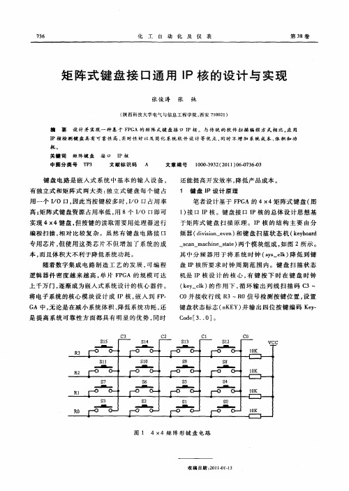
图 1 4×4矩 阵形 键 盘 电路
收 稿 日期 : 0 1 ) .3 2 1 41 1
第 6期
张俊 涛 等 . 阵 式 键 盘 接 口通 用 I 矩 P核 的设 计 与 实 现
; … : … ad sa …c b r c n mah o— — … e— tt a
s 7
■●
S 6
一
S 5
■■
S 4
-
R ro 1 _
S 3 -
ro .
S 2 -
。 厂 。
Sl ・_■ I_ -
’ 厂o o r 1 _ 一 l ’ 0 — K
S0 -_■■・-
R r。 o r。 o l - _
厂 。
上千万 门 , 逐渐 成 为嵌入 式系统设 计 的核心 器件 。
将 电子 系统 的核心 模块 设 计 成 I P核 , 入 到 F . 嵌 P
G 中, 论是在 减小 系统体积 、 低系统 功耗 , A 无 降 还
是 提高 系统 可靠 性 方面 都具 有 明显 的优 势 , 同时
C3 S1 5
基于FPGA的4x4键盘接口设计

library ieee;use ieee.std_logic_1164.all;use ieee.std_logic_arith.all;use ieee.std_logic_unsigned.all;entity smxh isport(clk: in std_logic;q_out: out std_logic_vector(1 downto 0);sm_out: out std_logic_vector(3 downto 0));end entity smxh;architecture art of smxh issignal sm_s: std_logic_vector(3 downto 0);signal q_s: std_logic_vector(1 downto 0);beginprocess(clk)isbeginif(clk'event and clk='1')thenif(q_s="11")thenq_s<="00";elseq_s<=q_s+1;end if;end if;end process;process(q_s)isbegincase q_s iswhen "00"=>sm_s<="0001"; ---------输出扫描信号为0001when "01"=>sm_s<="0010"; ---------输出扫描信号为0010when "10"=>sm_s<="0100"; ---------输出扫描信号为0100when "11"=>sm_s<="1000"; ----------输出扫描信号为1000when others=>sm_s<="1111";end case;end process;sm_out<=sm_s;q_out<=q_s;end architecture art;library ieee;use ieee.std_logic_1164.all;use ieee.std_logic_unsigned.all;use ieee.std_logic_arith.all;entity ymdl isport(clk: in std_logic;sm_in: in std_logic_vector(1 downto 0);jm_in: in std_logic_vector(3 downto 0);ym_out: out std_logic_vector(3 downto 0));end entity ymdl;architecture art of ymdl issignal jm_s: std_logic_vector(5 downto 0);signal ym_s: std_logic_vector(3 downto 0);beginprocess(clk)isbeginjm_s<=sm_in & jm_in;if(clk'event and clk='1')thencase jm_s iswhen "000001"=>ym_s<="0001"; ------译码值1when "000010"=>ym_s<="0010"; ------译码值2when "000100"=>ym_s<="0011"; ------译码值3when "010001"=>ym_s<="0100"; ------译码值4when "010010"=>ym_s<="0101"; ------译码值5when "010100"=>ym_s<="0110"; ------译码值6when "100001"=>ym_s<="0111"; ------译码值7when "100010"=>ym_s<="1000"; ------译码值8when "100100"=>ym_s<="1001"; ------译码值9when "110001"=>ym_s<="0000"; ------译码值0when others=>ym_s<="XXXX";end case;end if;end process;ym_out<=ym_s;end architecture art;3.2.5 键盘扫描程序的顶层文件设计library ieee;use ieee.std_logic_1164.all;use ieee.std_logic_unsigned.all;entity smgxs isport(ym_in: in std_logic_vector(3 downto 0);com0: out std_logic;qout8: out std_logic_vector(7 downto 0));end entity smgxs;architecture art of smgxs issignal qout8_s: std_logic_vector(7 downto 0);beginprocess(ym_in)isbegincase ym_in iswhen "0000"=>qout8_s<="11000000";----0when "0001"=>qout8_s<="11111001";----1when "0010"=>qout8_s<="10100100";----2when "0011"=>qout8_s<="10110000";----3when "0100"=>qout8_s<="10011001";----4when "0101"=>qout8_s<="10010010";----5when "0110"=>qout8_s<="10000010";----6when "0111"=>qout8_s<="11111000";----7when "1000"=>qout8_s<="10000000";----8when "1001"=>qout8_s<="10010000";----9when others=>qout8_s<="11111111";end case;end process;qout8<=qout8_s;com0<='1';end architecture art;library ieee;use ieee.std_logic_1164.all;use ieee.std_logic_unsigned.all;use ieee.std_logic_arith.all;entity smsz isGeneric(n:integer:=20);port(clk: in std_logic;ym_clk: out std_logic;xd_clk: out std_logic);end entity smsz;architecture art of smsz isSIGNAL cnt: std_logic_vector( n-1 downto 0);beginprocess(clk)isbeginif(clk'event and clk='1')then -----------上升沿IF(CLKin'EVENT AND clkin='1' ) THENCnt<=cnt+1;End if;End process;ym_clk<=cnt(17);xd_clk<=cnt(19);end architecture art;library ieee;use ieee.std_logic_1164.all;use ieee.std_logic_unsigned.all;use ieee.std_logic_arith.all;entity ymdl isport(clk: in std_logic;sm_in: in std_logic_vector(1 downto 0);jm_in: in std_logic_vector(3 downto 0);ym_out: out std_logic_vector(3 downto 0));end entity ymdl;architecture art of ymdl issignal jm_s: std_logic_vector(5 downto 0);signal ym_s: std_logic_vector(3 downto 0);beginprocess(clk)isbeginjm_s<=sm_in & jm_in;if(clk'event and clk='1')thencase jm_s iswhen "000001"=>ym_s<="0001"; ------译码值1when "000010"=>ym_s<="0010"; ------译码值2when "000100"=>ym_s<="0011"; ------译码值3when "010001"=>ym_s<="0100"; ------译码值4when "010010"=>ym_s<="0101"; ------译码值5when "010100"=>ym_s<="0110"; ------译码值6when "100001"=>ym_s<="0111"; ------译码值7when "100010"=>ym_s<="1000"; ------译码值8when "100100"=>ym_s<="1001"; ------译码值9when "110001"=>ym_s<="0000"; ------译码值0when "001000"=>ym_s<="1010"; ------译码值Awhen "011000"=>ym_s<="1011"; ------译码值Bwhen "101000"=>ym_s<="1100"; ------译码值Cwhen "111000"=>ym_s<="1101"; ------译码值Dwhen "110100"=>ym_s<="1110"; ------译码值Ewhen "110010"=>ym_s<="1111"; -------译码值Fwhen others=>null;end case;end if;end process;ym_out<=ym_s;end architecture art;library ieee;use ieee.std_logic_1164.all;use ieee.std_logic_unsigned.all;entity smgxs isport(ym_in: in std_logic_vector(3 downto 0);com0: out std_logic;com1: out std_logic;qout8: out std_logic_vector(7 downto 0));end entity smgxs;architecture art of smgxs issignal qout8_s: std_logic_vector(7 downto 0);beginprocess(ym_in)isbegincase ym_in iswhen "0000"=>qout8_s<="11000000";----0when "0001"=>qout8_s<="11111001";----1when "0010"=>qout8_s<="10100100";----2when "0011"=>qout8_s<="10110000";----3when "0100"=>qout8_s<="10011001";----4when "0101"=>qout8_s<="10010010";----5when "0110"=>qout8_s<="10000010";----6when "0111"=>qout8_s<="11111000";----7when "1000"=>qout8_s<="10000000";----8when "1001"=>qout8_s<="10010000";----9when "1010"=>qout8_s<="10001000";----Awhen "1011"=>qout8_s<="10000000";----Bwhen "1100"=>qout8_s<="11000110";----Cwhen "1101"=>qout8_s<="11000000";----Dwhen "1110"=>qout8_s<="10000110";----Ewhen "1111"=>qout8_s<="10001110";----Fwhen others=>qout8_s<="11111111";end case;end process;qout8<=qout8_s;com0<='1';com1<=”0”;end architecture art;library ieee;use ieee.std_logic_1164.all;use ieee.std_logic_arith.all;use ieee.std_logic_unsigned.all;entity smxh isport(clk,reset: in std_logic;sm_out: out std_logic_vector(3 downto 0)); end entity smxh;architecture art of smxh issignal sm_s: std_logic_vector(3 downto 0);beginprocess(clk,reset)isbeginif reset=’0’;sm_s<=”0001”;elsif (clk'event and clk='1') thensm_out<=sm_s;case sm_s iswhen "0001"=> sm_s <="0010";-when "0010"=> sm_s <="0100";-when "0100"=> sm_s <="1000";-when "1000"=> sm_s <="0001";-when others=> sm_s <="0001";end case;end if;end process;end architecture art;7。
基于FPGA的矩阵键盘接口电路的设计

目录目录------------------------------------------------------------------------------------------------ 1 1.绪论--------------------------------------------------------------------------------------------- 3 1.1 FPGA概况----------------------------------------------------------------------------------- 3 1.2 本课题的研究意义 ----------------------------------------------------------------------- 41.3 本章小结------------------------------------------------------------------------------------ 42. VHDL语言 ------------------------------------------------------------------------------------ 5 2.1 VHDL语言概述----------------------------------------------------------------------------- 5 2.2 VHDL语言的优点-------------------------------------------------------------------------- 6 2.3 利用VHDL语言设计数字系统的特点------------------------------------------------- 8 2.4 VHDL语言的基本结构-------------------------------------------------------------------- 92.5本章小结 ------------------------------------------------------------------------------------ 93.矩阵键盘接口电路原理和数码管显示原理 ------------------------------------------- 10 3.1矩阵键盘接口电路的原理 -------------------------------------------------------------- 10 3.2数码管显示原理 -------------------------------------------------------------------------- 123.3本章小结 ----------------------------------------------------------------------------------- 124.总体设计和各模块设计 ------------------------------------------------------------------- 13 4.1时钟产生模块 ----------------------------------------------------------------------------- 134.2键盘扫描模块 ----------------------------------------------------------------------------- 13 4.3数码管显示模块 -------------------------------------------------------------------------- 14 4.4顶层电路实现 ----------------------------------------------------------------------------- 14 4.5本章小结 ----------------------------------------------------------------------------------- 14 附录1:总体设计电路原理图:------------------------------------------------------------- 15附录2:硬件实物图 -------------------------------------------------------------------------- 15附录3:EP1C3T144C8N的PCB电路图 ---------------------------------------------------- 16附录4:顶层电路实现的具体程序 -------------------------------------------------------- 16附录5:时钟产生模块实现的具体程序 -------------------------------------------------- 17附录6:键盘扫描模块实现的具体程序 -------------------------------------------------- 18附录7:数码管显示模块实现的具体程序 ----------------------------------------------- 245.心得体会-------------------------------------------------------------------------------------- 261.绪论1.1 FPGA概况早期的可编程逻辑器件只有可编程只读存储器(PROM)、紫外线可擦除只读存储器(EPROM)和电可擦除只读存储器(E2PROM)三种。
基于EDA的矩阵键盘设计

学号 14082101445 成绩:信息学院《EDA技术及应用》课程论文题目:基于FPGA的矩阵键盘设计作者罗诗雨班级 08-1BF 系别信息学院专业自动化完成时间 2010年12月12日1 绪论随着人们生活水平的提高,19世纪兴起的数字电路以其先天的便捷、稳定的优点在现代电子技术电路中占有越来越重要的地位。
数字电路与模拟电路相比有显而易见的稳定性。
近年来,数字电路又有了巨大的发展。
可编程逻辑器件(PAL、GAL等)的发展和普及最终使IC的设计面向了用户(这是模拟电路无法做到的),而这毫无疑问会给用户带来巨大的便捷,从而奠定它在电子电路中的对位。
FPGA是英文Field Programmable Gate Array的缩写,即现场可编程门阵列,它是在PAL、GAL、EPLD等可编程器件的基础上进一步发展的产物。
它是作为专用集成电路(ASIC)领域中的一种半定制电路而出现的,既解决了定制电路的不足,又克服了原有可编程器件门电路数有限的缺点。
FPGA采用了逻辑单元阵列LCA(Logic Cell Array)这样一个新概念,内部包括可配置逻辑模块CLB (Configurable Logic Block)、输出输入模块IOB(Input Output Block)和内部连线(Interconnect)三个部分。
此次设计即为基于FPGA的矩阵键盘设计。
1.1 4×4矩阵键盘的工作原理在矩阵式键盘中,每条水平线和垂直线在交叉处不直接连通,而是通过一个按键加以连接。
这样,一个端口(如P1口)就可以构成4*4=16个按键,比之直接将端口线用于键盘多出了一倍,而且线数越多,区别越明显,比如再多加一条线就可以构成20键的键盘,而直接用端口线则只能多出一键(9键)。
由此可见,在需要的键数比较多时,采用矩阵法来做键盘是合理的。
1.2矩阵键盘的功能特点在键盘中按键数量较多时,为了减少I/O口的占用,通常将按键排列成矩阵形式,在矩阵键盘中每条水平线和垂直线在交叉处不直接相连,而是通过一个按键相连接,这样在由N条水平线和M条垂直线最多可以有N *M 个按键,大大的减少了对于芯片I/O的占用。
FPGA矩阵键盘显示电路的设计实验报告
三、实验数据处理、误差计算及讨论
当设计文件加载到目标器件后,将数字信号源模块的时钟选择为1KHZ,按下矩阵
湖南科技大学
物理与电子科学学院专业实验报告实验课程:FPGA实验
实验项目:矩阵键盘显示电路的设计
专业:
班级:
姓名:
学号:
实验日期:年月日
明,这里不在赘述。
本实验箱上的4X4矩阵键盘的电路原理如下图所示。
实现键盘有两种方案:一是采用现有的一些芯片实现键盘扫描;再就是用软件实
软件,新建一个工程。
VHDL File,打开VHDL编辑器对话框。
开关的不完善导致出现按键抖动。
成绩:教师:。
基于FPGA的RS232行列式矩阵键盘接口设计

基于FPGA的RS232行列式矩阵键盘接口设计
一、引言
本方案是用VHDL 语言来实现的基于RS232 按位串行通信总线的行列式矩
阵键盘接口电路,具有复位和串行数据的接收与发送功能,根据发光二极管
led0-led2 的显示状态可判断芯片的工作情况;实现所有电路功能的程序均是在美国ALTERA 公司生产的具有现场可编程功能的芯片EPM7128SLC84-15 上调试通过的。
能通过动态扫描来判有键按下、将键值转换成对应的ASCII 码值,在时钟脉冲的作用实现串行数据的接收与发送。
二、设计方案
1.芯片引脚定义
reset 复位输入端;clk 时钟输入端;rxd 串行数据接收端;retn0-retn7 键盘扫描行输入线;txd 串行数据发送端;scan0-scan7 键盘扫描列输出线;led0-led2 显示输出端。
2.键盘与芯片的连接图(如图2 所示,为8×8的64 键键盘)
3.动态扫描原理
(1)依次使列线scan0-scan7 输出0 电平,检查行线retn0-retn7 的电平状态。
如果行线retn0-retn7 的电平全为高电平,表示没键按下。
如果retn0-retn7 上的电平不全为高电平,表示有键按下。
(2)如果没键按下,就返回扫描。
有键按下则进行逐行扫描,找出闭合键的键。
基于FPGA的新型键盘_显示电路设计

基金项目:“八六三”计划资助项目(2002AA424054)收稿日期:2004-05-10 收修改稿日期:2004-10-02基于FPGA 的新型键盘、显示电路设计刘敬猛,王田苗,魏洪兴,王 伟(北京航空航天大学机器人研究所,北京 100083) 摘要:介绍一种基于FPG A 的键盘和显示电路的设计和实现。
利用FPG A 实现复杂时序的功能,同时结合使用串行输入/并行输出移位寄存器,设计了6位LE D 的动态显示和6个按键开关的键盘电路。
电路结构简单、便于扩展、可靠性高、易实现。
该电路已成功应用于研究的交流伺服系统中。
关键词:FPG A ;移位寄存器;动态显示中图分类号:TH703 文献标识码:B 文章编号:1002-1841(2005)03-0043-03Circuit Design of K eyboard and Display B ased on FPGA LIU Jing 2meng ,WANG Tian 2miao ,WEI H ong 2xing ,WANG Wei(R obotics Institute ,Beihang University of Aeronautics and Astronautics ,Beijing 100083,China )Abstract :Presented the design and realization of keyboard and display circuit.S ix LE D dynamic display and six keys keyboard cir 2cuit have been designed ,which uses the complex scheduling function of FPG A combined with the serial input/parallel output shift regis 2ters.The circuit possesses the characteristics such as simple structure ,high reliability ,and it is convenient to extend and easy to realize.This circuit has been success fully applied to AC serv o system.K ey Words :FPG A ;Shift Register ;Dynamic Display1 引言键盘分为编码键盘和非编码键盘[1]。
智能仪器设计报告——基于单片机和FPGA的矩阵键盘控制系统设计

目录1. 概述.................................................................................................. - 3 -2. 89C51单片机简介.......................................................................... - 3 -3. FPGA简介 ...................................................................................... - 3 -4. 矩阵键盘控制系统 ......................................................................... - 3 -4.1. FPGA设计框图 ..................................................................... - 3 -4.2. 单片机硬件实现 .................................................................... - 4 -4.3. 键盘控制系统子模块 ............................................................ - 4 -4.3.1 矩阵键盘原理 ................................................................. - 4 -4.3.2 时钟分频模块 ................................................................. - 5 -4.3.3 键盘扫描模块 ................................................................. - 6 -4.3.4 译码转换及三态门输出模块 ......................................... - 6 -4.3.5 单片机及液晶显示模块部分 ......................................... - 7 -5. 仿真及结果分析 ............................................................................. - 9 -5.1 分频模块时序仿真 ................................................................ - 9 -5.2 键盘扫描模块 ........................................................................ - 9 -5.3 译码输出模块 ........................................................................ - 9 -5.4 单片机与液晶显示器模块 .................................................. - 10 -6. 参考文献........................................................................................ - 11 - 致谢.................................................................................................... - 12 - 附录.................................................................................................... - 13 -1.概述随着可编程逻辑器件及EDA技术的发展,在系统设计中经常会用到FPGA来扩展单片机的相关资源。
- 1、下载文档前请自行甄别文档内容的完整性,平台不提供额外的编辑、内容补充、找答案等附加服务。
- 2、"仅部分预览"的文档,不可在线预览部分如存在完整性等问题,可反馈申请退款(可完整预览的文档不适用该条件!)。
- 3、如文档侵犯您的权益,请联系客服反馈,我们会尽快为您处理(人工客服工作时间:9:00-18:30)。
基于FPGA的键盘接口设计专业:电子信息科学与技术系作者:李先仙指导老师:刘强摘要:现场可编程逻辑门阵列FPGA (Field Programmalbe Gate Array)具有掩膜可编程门阵列的通用结构,由逻辑功能块排成阵列组成,并由可编程的互联资源连接这些逻辑功能块以及相应的输入/输出单元来实现不同的设计。
在电子产品中,键盘是最基本的输入设备,然而在应用中都采用通用的键盘扫描器件是不现实的,需要单独设计成专用的小键盘。
随着电子技术和EDA (Electronic Design Automatic,电子设计自动化)技术的发展,大规模可编程逻辑器件PLD(Programmable Logic Device)、现场可编程门阵列FPGA完全可以取代大规模集成电路芯片,实现计算机可编程接口的功能,并可将若干接口电路的功能集成到一片PLD或FPGA芯片中。
鉴于大规模PLD或FPGA的计算机接口电路不仅具有集成度高、体积小和功耗低等优点,而且还具有独特的用户可编程能力,从而实现计算机系统的功能重构。
本文设计首先介绍行列式键盘的原理和应用,通过对其接口电路的详细分析;然后利用VHDL硬件描述语言和FPGA器件并采用模块化设计的方法完成了基于FPGA的行列式键盘接口电路的设计;最后通过计算机仿真,对本文设计的行列式键盘接口电路的正确性进行了验证。
关键词:键盘;仿真;VHDL语言;FPGA;模块化设计Based on FPGA Keyboard Connection DesignMajor:Electronic Information Science and TechnologyAuthor: Li Xianxian Instructor: Liu QiangAbstract: The Filed Programmmalbe Gate Array,shorted by FPGA,which has a mask-programmable gate array of generic structure and function blocks in the logic array of line,through a programmable logic of internet resources connecting these function blocks and the corresponding input/output modules to achieve different design.In electronic products,the keyboard is the most basic input device,however,it’s unrealistic of using general keyboard scanning device in the application ,we need for the separate designing of the small keyboard. With the development of Electronic and EDA(Electronic Design Automatic)technology,Large Scale Integration chips can be replaced by PLD(Programmable Logic Device)and FPGA ,which can realize the function of the Programmable Interface chips and feature a number of interface circuits integated into one of the PLD or FPGA chips.The computer interface circuit based on the technology of PLD and FPGA not only has the virtue of high integration,low volume and low power loss, but also has the unique programmable function,which can realize reconstruction of the function of computer system.The designing of this article first introduced the determinant keyboard’s theory and application,through to analysis its connection electric circuit in very great detail ,and then used VHDL hardware description language and FPGA device to complete FPGA-based determinant keyboard connection electric circuit design with modular design mathod.Fianally,through the method of simulations to verify the accuracy of the determinant keyboard connection electric circuit of the design.Key words: Keyboard; Simulalion; VHDL lauguage; FPGA; Modular design前言键盘历史非常悠久,早在1714年,就开始相继有英、美、法、意、瑞士等国家的人发明了各种形式的打字机,最早的键盘就是那个时候用在那些技术还不成熟的打字机上的;到了20世纪中期,键盘又多了一个用武之地——作为电脑的基本输入设备,用户通过它向计算机传递信息,它有机械式、电容式、电感式和薄膜式等多种形式,按获取按编码的方式,可分为编码键盘和非编码键盘;根据键盘插口方式分为AT接口键盘和PS/2接口键盘和USB接口键盘,其中AT接口键盘目前已基本被淘汰[1]。
然而在应用中都采用通用的键盘扫描器件是不现实的,由可编程逻辑器件组成的数字电路系统中经常需要有输入/输出设备,以用来与用户更好地进行交互。
现代EDA(Electronic Design Automation,电子设计自动化)技术提供了一种很好的途径,利用VHDL硬件描述语言和FPGA器件可以很方便地构建键盘接口电路[2]。
本文采用VHDL语言设计的基于FPGA的行列式键盘接口设计,行列式键盘是常用的输入/输出设备之一,它结构简单,携带方便,功耗低,能够适用于各种功率要求的场合,功能强大,能有效的提高利用I/O口的利用率。
行列式键盘电路的FPGA实现主要解决三个问题,一是如何检测是否有按键按下并防止采集到干扰信号,二是在按键闭合时如何防止抖动,三是如何判断为哪一个按键位动作,并对其进行译码。
因此,要解决这些问题,把行列式键盘接口电路分为键盘扫描电路、键盘译码电路、按键标志产生电路、时钟模块以及键盘顶层电路等四个模块来实现。
首先利用VHDL硬件描述语言在FPGA芯片上实现键盘接口并利用仿真FPGA软件进行仿真;之后便可利用FPGA实验箱搭建相应的硬件电路,在硬件上实现键盘接口的一些基本功能。
在Altera、Atmel等公司都推出了内嵌微处理器的FPGA,但由于价格、开发手段和方法等因素的影响,在未来一段较长的时间里,还是会更多的采用单片机与FPGA配合的方式设计系统,以发挥单片机的灵活性和FPGA的高速性[3]。
1 VHDL和FPGA概述1.1 VHDL概述1.1.1 VHDL的由来和特点VHDL是Very high speed integrated circuit Hardware Deseription Language的缩写,意思是非常高速集成电路的硬件描述语言,是HDL(Hardware Deseription Language,硬件描述语言)的一种。
这是一项由美国国防部所支持的研究计划,目的是为了把电子电路的设计意义以文字或文件的方式保存下来,以便他人能轻易地了解电路的设计意义。
由于VHDL电路描述语言所能涵盖的范围很广,从ASIC(Application Specific Integrated Circuit,专用集成电路)的设计到PCB(Printed Circuit Board,印刷电路板)系统的设计,VHDL电路描述语言都能派上用场,所以VHDL语言毫无疑问地成为硬件设计工程师的必备工具[4]。
VHDL主要用于描述数字系统的结构、行为、功能和接口。
除了含有许多方面具有硬件特征的语句外,VHDL的语言形式和描述风格与句法十分类似于一般的计算机高级语言。
VHDL的程序结构特点是将一项工程设计或称设计实体(可以是一个元件、一个电路模块或一个系统)分成外部(即端口)和内部(即设计实体的内部功能和算法完成部分)。
在对一个设计实体定义了外部界面后,一旦其内部开发完成后,其它的设计就可以直接调用这个实体[5]。
这种将设计实体分成内、外两部分的概念是VHDL系统设计的基本点。
具体特点如下:1) 与其它的硬件描述语言相比,VHDL具有更强的行为描述能力,从而决定了它成为系统设计领域最佳的硬件描述语言。
强大的行为描述能力是避开具体的器件结构,从逻辑行为上描述和设计大规模集成电路的重要保证。
2) VHDL丰富的仿真语言和库函数,使得在大规模集成电路设计的早期就能查验出设计系统的功能可行性,可随时对设计进行功能仿真、时序仿真,使设计者在设计初期就可以对整个工程设计的可行性作出决策,从而缩短了设计周期,减少了研发成本。
3) VHDL语句的行为描述能力和程序结构决定了它具有支持大规模集成电路设计的分解和对已有设计的再利用功能[4]。
重复利用他人的IP (Intelligence Property core,知识产权核,一种正式注册产权的电路设计)模块和软核(soft core)是VHDL的特色,设计不必各个都从头再来,只要在更高的层次上把IP模块利用起来,能达到事半功倍的效果。
4) 对于VHDL完成的一个确定的设计,可以利用EDA工具(如MAX+PLUSⅡ)进行逻辑综合和优化,并自动把VHDL描述设计转换成门级网表。
这种设计方式突破了传统门级设计中的瓶颈,极大地减少了电路设计的时间和错误发生率,降低了开发成本,缩短了设计周期。