飞越真空计vmv-1说明书
VT CVT系列真空计和控制器使用说明书

VT/CVT SERIES VACUUM GAUGESand CONTROLLERSTELEDYNE HASTINGSINSTRUMENTSC E R T I F I E DManual Print HistoryThe print history shown below lists the printing dates of all revisions and addenda created for this manual. The revision level letter increases alphabetically as the manual undergoes subsequent updates. Addenda, which are released between revisions, contain important change information that the user should incorporate immediately into the manual. Addenda are numbered sequentially. When a new revision is created, all addenda associated with the previous revision of the manual are incorporated into the new revision of the manual. Each new revision includes a revised copy of this print history page.Revision A (Document Number 146-0497) ....................................................................... April 1997 Revision B (Document Number 146-0999) ............................................................... S eptember 1999 Revision C (Document Number 146-0301) ..................................................................... M arch 2001 Revision D (Document Number 146-0902) ............................................................... S eptember 2002 Revision E (Document Number 146-0805) .................................................................... August 2005 Revision F (Document Number 146-0710).......................................................................... J uly 2010 Revision F (Document Number 146-1111)................................................................ November 2011Visit for WEEE disposal guidance.Hastings Instruments reserves the right to change or modify the design of its equipmentwithout any obligation to provide notification of change or intent to change.The instruments described in this manual are designed for Class 2 installations in accordance with IAW/IPC standardsCAUTION:CAUTION:The instruments described in this manual are designed for INDOOR use only.The instruments described in this manual are available with multiple pin-outs. Ensure that all electrical connections are correct.CAUTION:Table of Contents1.1.F EATURES (4)1.2.S PECIFICATIONS (4)1.3.S AFETY (4)1.4.A CCESSORIES (5)1.5.DV-6S:N EW DV-6 TUBE F OR S EVERE E NVIRONMENTS (5)1.6.C ALIBRATION R EFERENCE T UBES (5)2.0INSTALLATION (6)2.1.P ANEL M OUNT V ACUUM G AUGE AND C ONTROLLER (6)2.2.C ABINET M OUNT V ACUUM G AUGE (7)2.3.E XTERNAL C ABLES AND W IRING (7)2.4.V ACUUM G AUGE T UBE (9)3.0VACUUM GAUGE OPERATION (10)3.1.M ETER M ECHANICAL Z ERO (10)3.2.AC I NPUT P OWER (10)3.3.P RESSURE M EASUREMENT (10)3.4.C ONTROLLER S ET P OINTS (CVT UNITS ONLY) (10)3.5.O PERATION AND P ERFORMANCE C HECK (10)3.6.G AUGE T UBE O PERATION (11)3.7.A NALOG P RESSURE M EASUREMENT (11)3.8.C ALIBRATION (13)3.8.1.C ALIBRATION U SING A V ACUUM S YSTEM (13)3.8.2.C ALIBRATION U SING A H ASTINGS R EFERENCE T UBE (13)4.0WARRANTY (14)4.1.W ARRANTY R EPAIR P OLICY (14)4.2.N ON-W ARRANTY R EPAIR P OLICY (14)This manual contains technical and general information relating to the installation, operation, and calibration of Hastings Vacuum Gauges, Controllers, and Gauge Tubes. For best performance, Hastings vacuum gauges should be operated with the appropriate Hastings gauge tube. Attempting to use a Hastings vacuum gauge with other manufacturer’s tubes may result in damage to both the gauge and tube.1.1. FeaturesHastings vacuum gauges and controllers are self-contained instruments that offer extreme versatility for most vacuum applications. The electronic design assures long life and minimal maintenance. Compact VT & CVT Models are ready for mounting onto a panel.Hastings vacuum gauges and controllers utilize Hastings rugged but sensitive gauge tubes which are designed specifically for each of the three available pressure ranges (consult Hastings Ordering and Dimension guide).1.2. SpecificationsPressure range:VT-4 series, CVT-14/24,................................................................................ 0-20 Torr or 0-20 mbar VT-5, CVT-15/25, ................................................................................. 0-100 mTorr or 0-0.1 mbar VT-6series, CVT-16/26, ......................................................................... 0-1000 mTorr or 0-1 mbar Input power ............................................................................................. 115 or 230 VAC, 50/60 Hz Output signal ....................................................................................... 0-1 VDC (analog, non-linear) Optional VT series Standard CVT seriesControl relays ..................................................................................... 5A @ 250 VAC (resistive load)5A @ 30 VDC (resistive load)Cables ..................................................................................................................... 6 ft (1.8 m) power8 ft (2.4 m) gauge tubeWeight:Panel mount meters ..................................................................................... 1.78 lb (0.81 kg) w/cables Panels mount controller’s ............................................................................. 2.13 lb (0.97 kg) w/cables Cabinet models .............................................................................................. 4.25 lb (2.0 kg) w/cables1.3. SafetyThe following symbols and terms may be found on THI products and/or in THI manuals and indicateimportant information.When found on the device, this symbol indicates that the operator should refer to the manual for important instructions on the proper use of this device. When found in a manual, this symbol indicates that the reader should understand the implications contained in the text before operating the device.The WARNING label indicates important information that should be heeded for safe and proper performance of the device.1.0The label, CAUTION, is used to indicate that damage to the power supply or equipment connected to it, could occur if directions are not followed. Warranty could be invalidated if the instructions in this manual are not followed.1.4. AccessoriesTHI offers a complete line of system attachments that permit easy maintenance for contaminated operations.Gauge tubes are offered with various system fittings tomatch almost any system requirement. Additionally, THI’s complete line of quick disconnect attachments allows customers to install these special fittings and easily replacesensors without vacuum sealant or Teflon® tape. For particularly dirty systems, Hastings offers a particle dropout trap containing a series of nine separate baffles which prevent solid contaminants from having a direct path tothe sensor’s thermopile.1.5. DV-6S: New DV-6 tube ForSevere EnvironmentsHastings Instruments has developed a new gauge tube, the DV-6S, which is specifically designed for outdoor use on cryogenic tanks including railcar and tanker truckapplications. In addition to the DAVC, the gauge tube is compatible with the hand-held HPM-4/6 and the analog VT-6. The DV-6S is supplied with a protective cap. The o-ring-sealed cap protects the gauge tube pins from moisture thussignificantly reducing corrosion. A metal lanyard prevents cap loss. The tube isprovided with a standard 1/8” NPT fitting; however special fitting requests can often be met.1.6. Calibration Reference TubesTHI Reference Tubes employ the samemetal thermopiles used in all THI Vacuum Gauge Tubes. The thermopile is sealed in a glass capsule that has been evacuated, baked, out-gassed, and then aged to ensure long-term stability. The sealed capsule is then housed in a protective metal shell to provide a rugged, trouble-free assembly.Once assembled, the reference gauge tube is accurately calibrated to precisely simulate a gauge tube at agiven operating pressure. It provides quick and easy instrument re-calibration by merely plugging the instrument and adjusting the calibration potentiometer until the display reads the exact pressure noted on the reference tube.Extension Cables for VT Series55-3 OM-8-OFV 8 Ft Extension Cable 55-22 OM-12-OFV 12 Ft Extension Cable65-53 OM-25-OFV 25 Ft Extension Cable 65-102 OM-50-OFV 50 Ft Extension Cable 55-142 OM-100-OFV 100 Ft Extension CableVacuum Gauge Tubes 1000 mTorr Range Stock # Model # Description 55-38 DV-6M 1/8” NPT Standard (Yellow base)55-38R DV-6R 1/8” Ruggedized 55-38RSDV-61/8” NPT Rohs Rugged55-38S DV-6S 1/8” NPT Rugged/Vibration 55-251 DV-6-KF-16 KF-16TM 55-267 DV-6-KF-25 KF-25TM55-283 DV-6-VCR VCR TM55-38R-CF DV-6R-CF Mini Conflat TMVacuum Gauge Tubes 100 mTorr Range55-19 DV-5M 1/8” NPT (Red Base) 55-230DV-5M -VCRVCR TMVacuum Gauge Tubes 20Torr Range55-19DV-4D1/8” NPT (Purple Base)55-19R DV-4R 1/8” NPT Ruggedized 55-258 DV-4D-KF-16 KF-16TM 55-266 DV-4D-KF-25 KF-25TM55-227 DV-4D-VCR VCR TMReference Tubes for use with VT/CVT55-104 DB-20 Ref Tube (DV-6) for DV-6 Calibration 55-101 DB-16D Ref Tube (DV-4D) for DV-4 Calibration 55-103DB-18Ref Tube (DV-5) for DV-5 Calibration2.02.2. Cabinet Mount Vacuum GaugeHastings cabinet models can be obtained with 2 - position or 5 - position tube switching functions that will allow the user to display pressure from one or more selected tubes. No special installation is necessary; simply connect the power cord and the gauge tube cables.Note: All of the gauge tube cables on either a 2-position or a 5-position unit must be equal in length. Mixing cable lengths on a particular unit will produce a calibration error due to the different resistances of the cables.2.3. External Cables and WiringWARNING: To prevent shock hazard to personnel, always install protective cover before application of AC power or prior to placing instrument in-service.VT series unitsConnect the AC power cable, gauge tube cable, and analog output (analog output is only available on units configured from the factory with 0-1 VDC) as detailed in figure 2-4. The terminal block protective cover must be removed to access screw terminals. Terminal FunctionDescription3 Gauge tube cable Heated T.C. (blk wire)4 AC power cable 115 VAC (blk wire) 5 Gauge tube cable Heated T.C. (wht wire)6 Gauge tube cable Compensated T.C. (green wire)7 Analog output (1vdc) Negative analog output terminal8 Analog output (1vdc) Positive analog output terminal9 AC power cable Lo VAC (wht wire) 10 AC power cable 230 VAC (blk wire) 13 COM chassis ground 14 COM AC power ground (green/yellow wire)WARNING:When 115 VAC is connected to the auto transformer, 230 VAC appears at the 230 VAC terminal. The same occurs when you attach 230 VAC to the unit, 115 VAC appearsat the 115 VAC terminal.CVT series unitsConnect the AC power cable, gauge tube cable, control relay and analog output (analog output is optional on VT and standard on CVT) as detailed in figure 2-5. The terminal block protective cover must be removed to access screw terminals.Fig 2.4VT Series Terminal BlockTERMINAL FUNCTION DESCRIPTION1Lo set relay (Normally Closed) relay contact 2 Lo set relay (Normally Open) relay contact 3 Gauge tube cable Heated T.C. (blk wire) 4 AC power cable 115 VAC (blk wire) 5 Gauge tube cable Heated T.C. (wht wire) 6 Gauge tube cable Compensated T.C. (green wire) 7 Analog output (1vdc) negative analog output terminal 8 Analog output (1vdc) positive analog output terminal 9 AC power cable Lo VAC (wht WIRE) 10 AC power cable 230 VAC (blk WIRE) 11 Spare no connection 12 Lo set relay (COM) relay contact 13 COM chassis ground 14 COM AC power ground (green/yellow wire) 15 Hi set relay (Normally Closed) relay contact 16 Hi set relay (Normally Open) relay contact 17Hi set relay (COM) relay contactWARNING:When 115 VAC is connected to the auto transformer, 230 VAC appears at the 230 VAC terminal. The same occurs when you attach 230 VAC to the unit, 115VAC appears at the 115 VAC terminal.Fig 2.5 CVT Series Terminal Block2.4.Vacuum Gauge TubeAll Hastings gauge tubes are shipped with a protective cap or cover at the evacuation port to reduce contamination and prevent physical damage to the internal thermopile elements. Once the protective cap or cover is removed, a tube can be installed in any convenient position in the vacuum system without adversely affecting calibration or performance. The recommended orientation is with the tube vertical and its stem down. This will aide in preventing condensable materials from remaining in the gauge tube.Hastings instruments also offer a wide variety of installation accessories for use with your vacuum gauge tube. Please consult the Hastings Ordering and Dimension Guide or contact your factory representative for information on these products.WARNING: Compression seal fittings “Quick-Connects” are not for use insystems where the tube can be pressurized above atmosphere.3.1. Meter Mechanical ZeroWith the gauge in its normal operating position (AC power removed), check that the meter pointer covers the Dot at right-end of the dial face. If the Dot is not covered by the pointer, adjust screw at the front of the meter until the pointer covers the Dot.3.2. AC Input PowerConnect the plug end of power cable into a single phase 115 or 230 V, 50/60 Hz power source (as per unit configuration). When replacing the power cords standard plug with a plug to match a particular system, care should be taken to connect the new plug in accordance with the terminal block connections listed in section 2.4 of this manual.3.3. Pressure MeasurementConnect gauge tube cables octal socket onto the octal base of a gauge tube installed in vacuum system. The gauge will display the system pressure on the meter dial face. To check the accuracy of the gauge, perform the required operations as specified in section 3.5 of this manual.3.4. Controller Set Points (CVT units only)The CVT series vacuum controllers are provided with either single or double set points. On a single set point controller, the right-front panel knob allows the user to adjust or position the “RED” pointer on the dial face where a desired control function will occur.On the double set point controller, the left-front panel knob is added to allow the user to adjust or position a second “RED” pointer on the dial face where a desired control function will occur.On those controllers configured with two front panel knobs; the left knob controls the LO Set pressure (Relay K1), and the right knob controls the HI Set pressure (Relay K2). Control logic determines that a relay will (energize) when the indicated pressure is lower than the set-pressure, and de-energize when the indicated pressure is higher than the set-pressure or if their is a loss of AC power to the unit.3.5. Operation and Performance CheckAll Hastings vacuum gauges, controllers, and tubes have been carefully calibrated and checked at the factory before shipment. When a operational check or calibration is desired, refer to the procedure outlined in this section.The simplest and quickest way of checking the operation and performance of a gauge and/or gauge tube is to maintain a new or known-good gauge tube on hand for use as a Reference. To check operation, install both the Reference and suspect gauge tubes in a common vacuum3.0 To avoid relay chatter, keep the lower set point above the ultimate system pressureCAUTION:system (locate the gauge tubes as close as possible to each other), then evacuate the system until a stable base pressure is obtained. Alternately connect the vacuum gauge to each gauge tube and record its pressure readings. If the gauge tube-under-test produces a higher pressure reading than the Reference gauge tube, this indicates a calibration shift and is usually the result of contamination (particulate, oil, or other chemical deposits). You can try to restorecalibration of the contaminated gauge tube by cleaning it internally with an appropriate solvent such as high-purity isopropyl alcohol (flood interior cavity of gauge tube gently with solvent and allow it to stand and soak for about 15 to 30-minutes). Drain the contaminated solvent and let gauge tube dry in ambient air until all of the cleaning solvent has evaporated. Toprevent mechanical damage to the thermopile elements, do not use forced air to dry the gauge tube. Gauge tubes that remain out of3.6. Gauge Tube OperationOperation of the Hastings gauge tube isin the gauge tube changes the molecularcollision rate and therefore the thermalconduction of the gas or gas mixturetemperature shift in the AC heatedthermocouples A and B (Fig. 3.1). Thethe DC output from couples A and B3.7. Analog Pressure MeasurementAn analog Signal Output line, pin 8, supplies a 0 to 1 VDC signal corresponding to the output range of the selected tube. This signal should be measured with respect to the analog Signal Common line, pin 7. See the INSTALLATION section for a diagram showing the Analog Signal pin out.This signal is equal to an amplified tube millivolt signal. This signal will NOT be linearly proportional to the indicated pressure. 1 volt will correspond to a system pressure that is at least 1 order of magnitude less than the minimum detectable pressure. Increasing pressure will be indicated by adecreasing voltage. The minimum detectable pressure is 0.2 millitorr for DV-5, 1 millitorr for DV-6 and 20 millitorr for DV-4.The voltage signal can be mapped to a pressure value by using the following equation.Where:V = VoltageP = pressure in Torr for DV4 & DV5 versions and millitorr for DV6 See Chart below221dV bV eV cV a P ++++=Parameters DV6DV4DV5a -1623.22-5.10184-0.25948b -58.0442-6.91233-42.23869c -11732.2-4.4943-2.92598d -130.397-6.30995-256.9951e 13338.179.563177 3.180163.8.CalibrationUsing a vacuum system to calibrate a gauge or gauge/tube combination will result in a more accurate pressure measurement. For instances where this is not possible, calibrating the gauge using a Hastings reference tube provides the best alternative.NOTE: For cabinet models, the top-cover must be removed to access the CAL control.3.8.1.Calibration Using A Vacuum SystemInstall the gauge tube in a vacuum system (gauge connected to AC power and stabilized), then evacuate to a pressure one decade or more below the gauge dial face resolution. Connect the gauge to tube and wait until the displayed pressure is stable.NOTE: When using a DV-4 type gauge tube, system pressure must be less than 1.0 x10⁻² Torr.When using DV-5 or DV-6 type gauge tubes, system pressure must be less than 1.0 x 10⁻⁵ Torr.Adjust the gauge CAL. adjustment (figure 3.2) until the meter pointer indicates zero-left on the dial face.3.8.2.Calibration Using A Hastings Reference TubeConnect a Hastings reference tube to a stabilized vacuum gauge. Wait until the displayed pressure is stable.NOTE: The following table specifies the Hastings reference tube to be used in the calibration of a gauge based upon the type of gauge tube being used:Reference tube Gauge tubeDB-16D DV-4DB-18 DV-5DB-20 DV-6Adjust the gauge CAL control (figure 3.2) until the meter pointer indicates the pressure specified on the decal of the reference tube in use.Fig 3.2calibration points4.04.1.Warranty Repair PolicyHastings Instruments warrants this product for a period of one year from the date of shipment to be free from defects in material and workmanship. This warranty does not apply to defects or failures resulting from unauthorized modification, misuse or mishandling of theproduct. This warranty does not apply to batteries or other expendable parts, nor to damagecaused by leaking batteries or any similar occurrence. This warranty does not apply to anyinstrument which has had a tamper seal removed or broken.This warranty is in lieu of all other warranties, expressed or implied, including any implied warranty as to fitness for a particular use. Hastings Instruments shall not be liable for anyindirect or consequential damages.Hastings Instruments, will, at its option, repair, replace or refund the selling price of the product if Hastings Instruments determines, in good faith, that it is defective in materials orworkmanship during the warranty period. Defective instruments should be returned toHastings Instruments, shipment prepaid, together with a written statement of the problemand a Return Material Authorization (RMA) number. Please consult the factory for your RMAnumber before returning any product for repair. Collect freight will not be accepted.4.2.Non-Warranty Repair PolicyAny product returned for a non-warranty repair must be accompanied by a purchase order, RMA form and a written description of the problem with the instrument. If the repair cost ishigher, you will be contacted for authorization before we proceed with any repairs. If you thenchoose not to have the product repaired, a minimum will be charged to cover the processingand inspection. Please consult the factory for your RMA number before returning any productrepair.TELEDYNE HASTINGS INSTRUMENTSAVENUENEWCOMBE804HAMPTON, VIRGINIA 23669 U.S.A.ATTENTION: REPAIR DEPARTMENT723-6531TELEPHONE (757)1-800-950-2468FAX (757)723-3925MAIL mailto:*********************************EINTERNET ADDRESS Repair Forms may be obtained from the “Information Request” section of the Hastings Instruments。
VACUU·VIEW 真空规操作说明书

真空系统技术真空规VACUU·VIEW VACUU·VIEW extended出版信息原版说明书请妥善保管,以备以后使用!本手册只能在完整且未经改动的情况下使用和传播。
用户必须仔细检查本手册是否适合其所有的产品。
感谢您购买VACUUBRAND GMBH + CO KG的产品。
您选择了一款技术水平极高的现代化产品。
目录目录1 简介 51.1 用户信息 (5)1.2 文档简介 (6)1.2.1 显示规则 (6)1.2.2 处理说明(操作步骤) (7)1.2.3 缩写 (7)1.2.4 术语定义 (8)2 安全说明 92.1 使用前注意事项 (9)2.2 不当使用 (9)2.3 一般安全说明 (10)2.3.1 安全注意事项 (10)2.3.2 人员 (10)2.3.3 ATEX类别 (11)2.4 正确处置 (12)3 产品描述 133.1 VACUU.VIEW真空规 (14)3.1.1 设计 (14)3.1.2 设备视图 (15)3.2 应用示例 (16)4 连接和操作 174.1 连接 (17)4.1.1 安装 (17)4.1.2 真空连接 (18)4.1.3 电气连接 (19)4.1.4 控制器、真空规和VACUU.BUS® (21)4.2 操作 (23)4.2.1 显示元件 (23)4.2.2 操作按键 (24)4.2.3 菜单结构 (25)5 操作 305.1 真空测量 (30)5.2 压力读数 (30)目录5.3 校准 (31)5.3.1 传感器校准概述 (31)5.3.2 在大气压下进行校准 (32)5.3.3 校准为参考压力 (33)5.3.4 在真空下校准 (34)6 服务菜单 356.1 更新 (35)6.1.1 准备工作 (35)6.1.2 更新真空规 (37)6.2 出厂设置 (39)6.3 “诊断”子菜单 (40)7 解决问题 417.1 错误显示 (41)7.2 故障 – 原因 – 纠正措施 (42)8 清洁 458.1 外壳表面 (45)8.2 传感器 (45)9 附录 469.1 技术信息 (46)9.1.1 技术数据 (46)9.1.2 沾湿材料 (48)9.1.3 铭牌 (49)9.2 订购信息 (50)9.3 服务 (51)9.4 索引 (52)9.5 VACUU.VIEW extended菜单结构概览 (55)9.6 符合性声明 – 中国RoHS 2 (56)简介1 简介本手册是产品的重要组成部分。
真空机组使用说明及注意事项(三篇)

真空机组使用说明及注意事项一真空机组开机流程1、启动VB150维持泵,然后打开出口阀。
当电阻计2真空度达到5帕以下时,启动扩散泵加热。
2、启动VB200旋片泵,打开旁通阀;当电阻计1真空度达到xx 帕以下时,开启2ZJP300罗茨泵,进行预抽。
3、扩散泵加热50分钟以上且电离计真空达到5帕以下时,先关闭旁通阀,再打开主阀,进行主抽。
4、关闭2ZJP300罗茨泵,30秒后关闭VB200旋片泵。
二真空机组关机流程1、关闭主阀。
2、启动-----关机程序。
三真空机组使用注意事项1、真空机组在使用的整个过程中,必须保证水路、气路完整通畅。
2、必须严格按照真空机组的开机、关机流程,进行操作。
3、扩散泵加热过程中,若不慎断水。
应先关闭扩散泵电源,再关闭主阀。
然后摘下扩散泵电炉加热器,并使用电风扇进行降温。
在这过程中,要一直保持VB150维持泵和出口阀处于开启状态。
4、扩散泵加热过程中,若VB150维持泵出现故障不工作,应先关闭出口阀,然后启动VB200旋片泵,再启动2ZJP300罗茨泵,打开维持阀进行主抽。
真空机组使用说明及注意事项(二)一、真空机组的概述真空机组是一种用于产生、维持和控制特定压力范围内的真空的设备。
它主要由真空泵、真空计、阀门等组成,通过这些设备的协作实现真空的生成和控制,为实验室、生产工艺或其他应用提供所需的真空环境。
二、真空机组的使用说明1. 安装位置选定真空机组安装应选择通风良好、干燥且无尘、无震动的场所。
要避免阳光直射和高温环境,以确保机组正常运行和延长使用寿命。
2. 电源和电气连接在使用真空机组之前,确认电源电压和频率与机组要求一致。
正确接地电源线,并按照接线图连接电源。
3. 维护保养真空机组应定期进行维护保养,包括清洁除尘、润滑和更换易损件等。
特别注意保持泵内干燥,防止泵叶生锈和腐蚀,影响真空度。
4. 开机前准备在启动真空机组之前,应检查各个部件是否正常,确保泵油达到标准液位,检查阀门是否关闭,以及泵是否连接好并无漏气。
自动真空阀 AVPVM-F R N 产品手册说明书
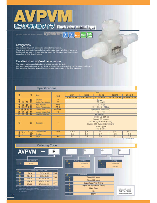
ʷ
ʷ
˘
ʷ ʷ
ʷ ʷ
˘
ʷ ʷ
ʷ ʷ
˘
˞1: In the case of the connection is "F","R" or "N", only "I (Inch)" can be selected for the "Tubing Standard".
'MPXFMMTFSJFT
'MPXFMMTFSJFT " 4VQFS5ZQF1JMMBS'JUUJOH
4VQFS5ZQF1JMMBS'JUUJOH 'MBSF5ZQF 3Dɺ'/15
# $ % & ' ( )
4UBOEBSE
JODI NN JODI NN JODINN JODINN JODI JODI
ᶅ ̨ ̛˞ ̧˞ ̣˞
Connection 'MPXFMMTFSJFT 'MPXFMMTFSJFT
4VQFS5ZQF1JMMBS'JUUJOH 4VQFS5ZQF1JMMBS'JUUJOH
'MBSF5ZQF 3D
'/15
Ordering code example
Unit
ʵ ˆ .1B .1B DNNJO ˆ ʵ
ଓ Connection
ʵ
Φ Ϧ ϑ Ο ε˞ Orifice diameter
NN
$ W ɹ ˞ Cv value
ʵ
ॏ
ྔ Weight
LH
ʷ ʷ
П
Size
V2M-1-00中文说明书(1)

气体检测报警装置用指示计单元V2M-1-1型V2M-2-1型使用说明书● 请将本使用说明书尽量靠近身边慎重保管,以便在需要时能立即取出来阅读使用。
● 请认真仔细阅读本使用说明书,理解熟悉书中内容后再正确使用本仪器。
新宇宙电机株式会社使用说明书管理编号GAU-034-001997年9月编制目 录1. 前言 (1)2. 为了正确使用本仪器 (2)3. 包装内物品的说明 (3)4. 系统构成 (4)5. 外形尺寸和各部的名称 (5)6. 安装以及配线方法6-16-2 7. 安装方法……………………………………………………………………………配线连接方法………………………………………………………………………使用方法……………………………………………………………………………79148. 维修保养检查 (21)9. 考虑为仪器故障之前 (22)10. 规格 (23)11. 关于售后保证 (24)12. 用语的说明 (25)1. 前言承蒙购买气体检测报警器指示计组件V2M-1-1型(1段报警用)、V2M-2-1型(2段报警用),在此表示衷心感谢。
本仪器是将通过气体检测部检测到的半导体制造工厂等处的气柜,一般排气管道,工作环境内的半导体材料气体或者氢气等可燃性气体的泄漏情况,转换成的模拟信号予以接受的装置。
本仪器由气体检测报警装置的指示计组件,将现场的气体浓度转换成电气信号的检测部PS-6(吸引式),KS-6(扩散式)构成一个回路,再和报警器组件VAL-1(1段报警用),VAL-2型(2段报警用)(带有蜂鸣器报警功能)等组合,构成一个系统。
为了正确使用本仪器,请务必在使用前认真仔细的阅读本使用说明书。
此外,也请同时阅读气体检测部,报警器组件等的使用说明书。
特殊标记的说明为了让用户安全使用本仪器,本文使用了下列特殊标记。
△!危险:该标记表示如果不回避的话,就会立即发生导致死亡或人身受重伤等紧迫的危险情况。
△!警告:该标记表示如果不回避的话,就可能会发生导致死亡或人身受重伤等危险情况。
真空机使用说明书

真空包装机使用规范1. 目的为使作业员能熟练掌握并操作真空包装机。
2. 适应范围本公司所属真空包转均可适用之,用于真空封口包装。
3. 定义真空包装机DZ500-1D。
4. 责职无5. 流程图无6.主要结构与工作原理本机主要由上工作室、下工作平台、机架、电气系统、真空系统五大部分组成。
工作过程:首先合盖,真空泵从工作室抽气,当达到预定真空度时,真空泵停止工作,加压阀打开,气囊充气,压条向下压紧封口处,同时通电加热,包装袋封口完备后放气阀通电打开,自动放气开盖完成一次工作循环。
7.调整与使用①使用前的准备a、机器放置平稳,察看合盖是否顺利,松手后是否自动跳起,但跳起的力不能过大;DZ-500/2S、DZ-600/2S、DZ-700/2S机型则调整左右螺旋扣。
b、配备适应机型要求的电源。
c、察看真空泵油面的位置是否正确,如不正确应调整(详见真空泵说明书。
d、将本机良好接地。
e、接通电源,打开电源开关,合盖,察看真空泵运转是否正常。
(如不抽气,应调换三相电源线中的任意两根线)。
②使用前的调整a、选择真空度抽气时间为0-99.9秒数显式连续可调,小型真空机,抽气时间为数字旋转式0-30秒可调。
调整抽气时间的长短,从而达到所需真空度。
b、选择加热温度根据包装袋材料选择所需加热温度,将加热温度旋钮调到相应位置,高或中或低。
c、调整加热时间加热时间0-9.99秒数显式连续可调。
根据所用包装材料及加热温度,调整加热时间旋钮,选择合适的加热时间d、根据需要选定封口硅橡胶条口的硅胶字,设定封口日期等字符。
③使用a、打开电源开关;b、将包装袋压条翻开,把装入被包装物品的包装袋(物品至口部不得小于4厘米)放入工作室内,需封口处平整地放于硅橡胶条上,袋子不要重叠。
翻过包装袋压条将包装袋口部压好;c、握住手把(或按上盖边缘)下压上工作室。
合盖,则本机将按程序自动完成真空包装过程并自动开盖,部分设备配备有急停开关;d、翻开包装袋压条。
真空计使用方法带参数要求说明

真空计使用方法带参数要求说明真空计是一种用于测量气体压力的仪器,广泛应用于科学研究、工业生产和实验室实践中。
本文将详细介绍真空计的使用方法,并说明其相关参数要求。
一、真空计的基本原理和种类真空计的基本原理是利用气体分子与传感器间的碰撞来测量气体压力。
根据不同的原理和测量范围,真空计可以分为多种类型,如电离真空计、热导真空计、毛细管真空计、扩散真空计等。
二、真空计的使用方法1.准备工作在使用真空计之前,需要进行一些准备工作:-清洁传感器:使用温和的洗涤剂和干净的布或棉签轻轻擦拭传感器表面,确保其光洁无尘。
-检查连接管路:确保所有连接管路的接口密封良好,避免气体泄漏。
-检查真空计仪器:确认仪器的电源、指示器和控制面板正常工作。
2.接通电源将真空计连接到电源,并打开电源开关,等待仪器进行自检和初始化。
根据具体型号,可能需要设置相关参数,如量程、单位等。
3.设置测量范围根据实际需求,设置真空计的测量范围。
对于不同的真空计类型,其测量范围可能有所不同,一般可调节量程旋钮或通过仪器控制面板进行设定。
4.进行标定(可选)如果需要更高的测量精度和准确性,可以进行标定过程。
标定过程可参考真空计的用户手册,常见的标定方法包括手动标定和自动标定,根据仪器的指示进行相应操作。
5.进行测量将真空计的传感器插入待测气体环境中,确保传感器完全暴露在气体中。
一般情况下,真空计会自动读取并显示气体压力值。
如需连续测量,可设定仪器的采样频率和测量间隔。
6.结束测量和关闭真空计当测量完成后,可在仪器上停止测量或选择保存测量数据。
然后,关闭真空计的电源开关,断开与气体环境的连接。
三、真空计使用时的参数要求1.真空计的精度和准确度要求根据实际应用而定,一般会标明在特定范围内的测量误差。
2.真空计的量程需根据实际测量范围来设定,并需保证测量数据在该范围内具有足够的准确性和可靠性。
3.真空计的响应时间要求取决于具体应用场景,一般要能够满足实时或近实时的测量需求,避免延迟和漏测。
电阻真空计使用说明书
MODBUS-ASCII格式
主机发送:
1 Byte
2 Bytes
2Bytes
2Bytes
2Bytes
2Bytes
2Bytes
2Bytes
2Bytes
:
从机地址
06
寄存器地址字节1
寄存器地址字节2
写入数据
字节1
写入数据字节2
校验码
CR LF
真空计应答:
1 Byte
2 Bytes
2Bytes
面板尺寸
150mm X 130mm
二、仪器安装说明
1
①:通道一测量真空度
②:通道二测量真空度
③:继电器开关指示
④:系统单位(Pa、mbar、Torr)
⑤:满调按键
⑦:设置键
⑥:零调按键
⑧:加/上翻键
⑨:减/下翻键
⑩:OK键
23 通道一电阻规接口
4 继电器输出接口
5 RS-232通信口
数据位宽度
8位
支持7位/8位/9位
校验位方式
无校验
支持无校验/奇校验/偶校验
停止位宽度
1位
支持1位/2位
数据格式
高字节在前,低字节在后
可选择高低字节互换
(2)、通信协议
DGR-52电阻真空计支持的功能码:
功能码
名称
说明
类型
01H
读取线圈状态
读取一个或多个离散量状态
读
03H
读取保持寄存器
读取保持寄存器当前值
MODBUS-RTU协议的数据帧格式为:
-
1 Byte
1Byte
1Byte
1Byte
- 1、下载文档前请自行甄别文档内容的完整性,平台不提供额外的编辑、内容补充、找答案等附加服务。
- 2、"仅部分预览"的文档,不可在线预览部分如存在完整性等问题,可反馈申请退款(可完整预览的文档不适用该条件!)。
- 3、如文档侵犯您的权益,请联系客服反馈,我们会尽快为您处理(人工客服工作时间:9:00-18:30)。
飞越真空计vmv-1说明书让您的工作更愉快
真空计
操作手册
VMV-1
品质保证
描述
VMV-1内置皮拉尼专业真空传感器,可以精确测量真空度。
因此,您可以从测量中收集有关湿度和异物(油、异物等)去除的息,从而了解填充制冷剂的最佳状态。
VMV-1可用于真空系统监测、泄漏检测和泵质量鉴别。
安全说明
操作应按照本指令进行,并在指定参数范围内。
电量不足时更换新电池。
请勿将新旧电池混用,禁止使用不同品牌的电池。
如果长时间不使用,请取出所有电池。
请勿使用腐蚀性清洁剂或溶剂清洁仪器。
戴上护目镜和防护手套。
拧紧铜盖并存放在干燥的地方。
仪器过view
1. 1/4“喇叭
2. :电源开/关/背光 UNIT:设置模式下的单
位选择/加值 SET:长按按钮进入闹钟设置模式 SAVE/CAL:
保存报警值/满量程校准/设置模式下的零位校准 3. 显示(真空度、单位和电池容量) 4. 电池盖(3xAA 电池)
技术参数
最大过载压力 14PSI / 0.1Mpa Range 0- 帕,0-100.00 毫巴,0-75.000 毫米汞柱,0- 微米分辨率 0.01 (<10 Pa), 0.0001 (<10 mBar),
0.0001 (<10 mmHg) , 1 (< 微米) 准确性 2-100 Pa:读数的
±5%(20t 时)工作温度 0–2-122 F) 电池寿命 45 小时(3 节
AA 电池)单位 Pa, mBar, mmHg, 微米刷新率 0.5第二连接
1×1/4″ 喇叭口传感器 lx 皮拉尼传感器自动关机时间 10分钟
背光时间 20秒蜂鸣器警报 90分贝,10秒后关闭重量约125
克(不含电池)应用大气环境(不能在
存在制冷剂和其他气体环境)
运营
安装三节“AA”电池。
长按电源键 CD 3 秒可打开 LCD 灯。
当设备完全预热时,显示屏显示“。
直接或通过连接附件连接
到系统。
启动真空泵,显示屏会从高到低显示极限压力。
达
到目标极限压力后,真空计蜂鸣报警,背光灯同时闪烁10秒。
按住电源按钮 0 3 秒可关闭电源。
单位选择
按 UNIT 按钮选择测量单位。
设置警报
长按“SET”键3秒进入设置模式。
按“SET”按钮选择数字
位置。
选择时,数字位置将闪烁。
按“UNIT”键修改闪烁值。
按“SAVE/CAL”按钮保存设定值。
真空泄漏报警器
当真空度变差到设定值时,真空计会蜂鸣报警,同时背光灯会闪烁。
逆光
按下电源按钮在仪器开机时打开背光。
背光将在 20 秒后自动关闭。
自动关闭
本机设置为 10 分钟无任何操作自动关机。
满量程校准
如果设备完成预热并且显示屏没有显示“----”,则在大气压下按住 SAVE/CAL 按钮 3 秒钟,直到显示屏显示“----”
零位校准
将真空计连接到真空系统,当系统真空度达到0.1 Pa时,长按“SAVE/CAL”键3秒,直到显示屏显示“0.1 Pa”,完成校零。
传感器清洁
在此过程中,有可能传感器被异物污染,此时需要对传感器进行清洁。
请遵循以下说明:
关闭真空计,取出所有电池。
抖掉异物。
使用滴管或注射器,用酒精或异丙醇填充传感器室。
拧紧铜盖,然后用酒精或异丙醇冲洗传感器室 3-4 次。
通过真空化或至少 2 小时风干彻底干燥传感器。
检查真空计并进行零位校准。
电池安装
取下电池仓盖,安装三节“AA”电池并确保其极性正确。
注意:如果仪器长期不使用,请取出仪器中的所有电池。
附录
3xAA 电池、连接配件、三通接头、说明。
故障排除
无法开机检查电池和极性极限真空不准确检查连接是否牢固。
零位校准/清洁传感器开机有真空度
而满量程不准确请在大气环境下进行全面校准。
如果制冷剂造成的满度不允许,请保持24小时后再校准满刻度。
华机电制品有限公司
地址:浙江省温岭市西部工业区九龙大道
Tel:+6-576- Fax:+6-576-
邮件:[电子邮件保护]。