5100FE 规格书
UC-5100系列硬件用户手册说明书

UC-5100 Series Hardware User’s ManualEdition 1.1, October 2018/product© 2018 Moxa Inc. All rights reserved.UC-5100 Series Hardware User’s Manual The software described in this manual is furnished under a license agreement and may be used only in accordance withthe terms of that agreement.Copyright Notice© 2018 Moxa Inc. All rights reserved.TrademarksThe MOXA logo is a registered trademark of Moxa Inc.All other trademarks or registered marks in this manual belong to their respective manufacturers.DisclaimerInformation in this document is subject to change without notice and does not represent a commitment on the part of Moxa.Moxa provides this document as is, without warranty of any kind, either expressed or implied, including, but not limited to, its particular purpose. Moxa reserves the right to make improvements and/or changes to this manual, or to the products and/or the programs described in this manual, at any time.Information provided in this manual is intended to be accurate and reliable. However, Moxa assumes no responsibility for its use, or for any infringements on the rights of third parties that may result from its use.This product might include unintentional technical or typographical errors. Changes are periodically made to the information herein to correct such errors, and these changes are incorporated into new editions of the publication.Technical Support Contact Information/supportMoxa AmericasToll-free: 1-888-669-2872 Tel: +1-714-528-6777 Fax: +1-714-528-6778Moxa China (Shanghai office) Toll-free: 800-820-5036Tel: +86-21-5258-9955 Fax: +86-21-5258-5505Moxa EuropeTel: +49-89-3 70 03 99-0 Fax: +49-89-3 70 03 99-99Moxa Asia-PacificTel: +886-2-8919-1230 Fax: +886-2-8919-1231Moxa IndiaTel: +91-80-4172-9088 Fax: +91-80-4132-1045Table of Contents1.Introduction ...................................................................................................................................... 1-1Overview ........................................................................................................................................... 1-2 Model Descriptions .............................................................................................................................. 1-2 Package Checklist ............................................................................................................................... 1-2 Product Features ................................................................................................................................ 1-3 Hardware Block Diagram ..................................................................................................................... 1-3 2.Hardware Introduction...................................................................................................................... 2-1Appearance ........................................................................................................................................ 2-2 LED Indicators .................................................................................................................................... 2-5 Reset Button ...................................................................................................................................... 2-5 Reset to Default Button ....................................................................................................................... 2-5 Real Time Clock .................................................................................................................................. 2-5 Installation Options ............................................................................................................................. 2-6 DIN-Rail Mounting ....................................................................................................................... 2-6Optional DIN-Rail Mounting .......................................................................................................... 2-6 3.Hardware Connection Description ..................................................................................................... 3-1Wiring Requirements ........................................................................................................................... 3-2 Connecting the Power .................................................................................................................. 3-2Grounding the Unit ...................................................................................................................... 3-2 Connecting to the Console Port ............................................................................................................. 3-3 Connecting to the Network ................................................................................................................... 3-3 Connecting to a Serial Device ............................................................................................................... 3-4 Connecting to a DI/DO Device .............................................................................................................. 3-4 Connecting to a CAN Device ................................................................................................................. 3-4 Connecting to a USB Device ................................................................................................................. 3-5 Connecting the Cellular/Wi-Fi Module and Antenna ................................................................................. 3-5 Installing Micro SIM Cards ................................................................................................................... 3-7 Installing the SD Card ......................................................................................................................... 3-8 Adjusting the CAN DIP Switch .............................................................................................................. 3-8 Adjusting Serial Port DIP Switch ........................................................................................................... 3-8 A.Regulatory Approval Statements ....................................................................................................... A-11Introduction The UC-5100 Series embedded computers are designed for industrial automation applications. The computers feature 4 RS-232/422/485 full-signal serial ports with adjustable pull-up and pull-down resistors, dual CAN ports, dual LANs, 4 digital input channels, 4 digital output channels, a SD socket, and a mini PCIe socket for wireless module in a compact housing with convenient front-end access to all these communication interfaces. The following topics are covered in this chapter:❒Overview❒Model Descriptions❒Package Checklist❒Product Features❒Hardware Block DiagramOverviewThe UC-5100 Series embedded computers are designed for industrial automation applications. The computers feature 4 RS-232/422/485 full-signal serial ports with adjustable pull-up and pull-down resistors, dual CANports, dual LANs, 4 digital input channels, 4 digital output channels, a SD socket, and a mini PCIe socket for wireless module in a compact housing with convenient front-end access to all these communication interfaces. Model DescriptionsThe UC-5100 Series includes the following models:•UC-5101-LX: Industrial computing platform with 4 serial ports, 2 Ethernet ports, SD socket, 4 DI, 4 DO, -10 to 60°C operating temperature range•UC-5102-LX: Industrial computing platform with 4 serial ports, 2 Ethernet ports, SD socket, mini PCIe socket, 4 DI, 4 DO, -10 to 60°C operating temperature range•UC-5111-LX: Industrial computing platform with 4 serial ports, 2 Ethernet ports, SD socket, 2 CAN ports,4 DI, 4 DO,-10 to 60°C operating temperature range•UC-5112-LX: Industrial computing platform with 4 serial ports, 2 Ethernet ports, SD socket, mini PCIe socket, 2 CAN ports, 4 DI, 4 DO, -10 to 60°C operating temperature range•UC-5101-T-LX: Industrial computing platform with 4 serial ports, 2 Ethernet ports, SD socket, 4 DI, 4 DO, -40 to 85°C operating temperature range•UC-5102-T-LX: Industrial computing platform with 4 serial ports, 2 Ethernet ports, SD socket, mini PCIe socket, 4 DI, 4 DO, -40 to 85°C operating temperature range•UC-5111-T-LX: Industrial computing platform with 4 serial ports, 2 Ethernet ports, SD socket, 2 CAN ports,4 DI, 4 DO, -40 to 85°C operating temperature range•UC-5112-T-LX: Industrial computing platform with 4 serial ports, 2 Ethernet ports, SD socket, 2 CAN ports, mini PCIe socket, 4 DI, 4 DO, -40 to 85°C operating temperature rangeNOTE The operating temperature range of the wide temperature models is:-40 to 70°C with an LTE accessory installed-10 to 70°C with a Wi-Fi accessory installed.Package ChecklistBefore installing a UC-5100 computer, verify that the package contains the following items:•UC-5100 Series computer•Console cable•Power jack•Quick Installation Guide (printed)•Warranty cardNotify your sales representative if any of the above items are missing or damaged.NOTE The console cable and power jack can be found beneath the molded pulp cushioning inside the product box.Product Features•ARMv7 Cortex-A8 1000 MHz processor•Dual auto-sensing 10/100 Mbps Ethernet ports• 4 software-selectable RS-232/422/485 ports supporting all signals•Dual Industrial CAN 2.0 A/B protocol supported•Moxa Industrial Linux with 10-year superior long term support•Mini PCIe socket for Wi-Fi/Cellular module•Micro SD socket for storage expansion•Supports TPM v2.0 (optional)•-40 to 85°wide temperature range and -40 to 70°C with LTE enabledFor a complete set of specifications, refer to the product datasheet available on the Moxa Website. Hardware Block Diagram2Hardware Introduction The UC-5100 embedded computers are compact and rugged, making them suitable for industrial applications. The LED indicators allow you to monitor performance and identify trouble spots quickly, and the multiple ports can be used to connect a variety of devices. The UC-5100 Series comes with a reliable and stable hardware platform that lets you devote the bulk of your time to application development. In this chapter, we provide basic information about the embedded computer’s hardware and its various components.The following topics are covered in this chapter:❒Appearance❒LED Indicators❒Reset Button❒Reset to Default Button❒Real Time Clock❒Installation OptionsD IN-Rail MountingO ptional DIN-Rail MountingAppearance Front ViewUC-5101UC-5102UC-5111UC-5112Dimensions [units: mm (in)] UC-5101UC-5102UC-5111UC-2112LED IndicatorsThe function of each LED is described in the table below: LED Name Status FunctionPower Green Power is on, and the device is functioning normally OffPower is offReadyYellow OS has been successfully enabled and the device is ready EthernetGreen Steady On: 10 Mbps Ethernet linkBlinking: Data transmission is in progress Yellow Steady On: 100 Mbps Ethernet linkBlinking: Data transmission is in progressOff Transmission speed below 10 Mbps or the cable is not connectedSerial (Tx) Green Serial port is transmitting data Off Serial port is not transmitting data Serial (Rx)Yellow Serial port is receiving data Off Serial port is not receiving dataL1/L2/L3(UC-5102/5112) YellowThe number of glowing LEDs indicates the signal strength. All LEDs: Excellent L1 & L2 LEDS : Good L1 LED : PoorOffNo wireless module detectedL1/L2/L3(UC-5101/5111)Yellow/OffProgrammable LEDs defined by usersReset ButtonThe UC-5100 computer is provided with a Reset button, which is located on the front panel of the computer. To reboot the computer, press the reset button for 1 second.Reset to Default ButtonThe UC-5100 is also provided with a Reset to Default button which can be used to reset the operating system back to the factory default status. Press and hold the Reset to Default button between 7 to 9 seconds to reset the computer to the factory default settings. When the reset button is held down, the Ready LED will blink once every second. The Ready LED will become steady when you hold the button continuously for 7 to 9 seconds. Release the button within this period to load the factory default settings.Real Time ClockThe UC-5100’s real time clock is powered by a non-chargeable battery. We strongly recommend that you do not replace the lithium battery without help from a qualified Moxa support engineer. If you need to change the battery, contact the Moxa RMA service team.Installation OptionsDIN-Rail MountingThe aluminum DIN-rail attachment plate is already attached to the product’s casing. To mount the UC-5100 on to a DIN rail, make sure that the stiff metal spring is facing upwards and follow these steps. Step 1Insert the top of the DIN rail into the slot just below the stiff metal spring in the upper hook of the DIN-rail mounting kit.Step 2Push the UC-5100 towards the DIN rail until theDIN-rail attachment bracket snaps into place.Optional DIN-Rail MountingThe UC-5100 can be mounted with the optional DIN rail mounting kit. Follow these steps for the installation. 1. Attach the optional DIN-rail mounting kit on therear panel with two screws.2. Pull down the slider of the DIN-rail bracketlocated at the back of the unit.3. Insert the top of the DIN rail into the slot justbelow the upper hook of the DIN-rail bracket. 4. Latch the unit firmly on to the DIN rail as shownin the illustrations below.5. Once the computer is mounted properly, youwill hear a click and the slider will rebound back into place automatically.Note this optional DIN-rail mounting kit should be purchased separately.3 Hardware Connection DescriptionIn this chapter, we describe how to connect the UC-5100 to a network and various devices for first time testing purposes.The following topics are covered in this chapter:❒Wiring RequirementsC onnecting the PowerG rounding the Unit❒Connecting to the Console Port❒Connecting to the Network❒Connecting to a Serial Device❒Connecting to a DI/DO Device❒Connecting to a CAN Device❒Connecting to a USB Device❒Connecting the Cellular/Wi-Fi Module and Antenna❒Installing Micro SIM Cards❒Installing the SD Card❒Adjusting the CAN DIP Switch❒Adjusting Serial Port DIP SwitchWiring RequirementsIn this section, we describe how to connect various devices to the embedded computer. Be sure to read and follow these common safety precautions before proceeding with the installation of any electronic device: • Use separate paths to route wiring for power and devices. If power wiring and device wiring paths mustcross, make sure the wires are perpendicular at the intersection point.NOTEDo not run signal or communication wiring and power wiring in the same wire conduit. To avoid interference, wires with different signal characteristics should be routed separately.• You can use the type of signal transmitted through a wire to determine which wires should be kept separate.The rule of thumb is that wiring that shares similar electrical characteristics can be bundled together. • Keep input wiring and output wiring separate.• When necessary, it is strongly advised that you label wiring to all devices in the system.Connecting the PowerTerminal BlockConnect the 9 to 48 VDC power line to the terminal block, which is connector to the UC-5100 Series computer. If the power is supplied properly, the “Power” LED will glow asolid green light. The power input location and pin definition are shown in the adjacent diagram.SG: The Shielded Ground (sometimes called Protected Ground) contact is at the bottomcontact of the 3-pin power terminal block connector when viewed from the angle shown here. Connect the wire to an appropriate grounded metal surface or through the groundingscrew on top of the device.Grounding the UnitGrounding and wire routing help limit the effects of noise due to electromagnetic interference (EMI). Run the ground connection from the ground screw to the grounding surface prior to connecting devices.Connecting to the Console PortThe UC-5100’s console port is a 4-pin pin-header RS-232 port located on the top panel of the case. It is designed for serial console terminals, which are useful for identifying the boot up message, or for debugging when the system cannot boot up.PIN Signal1 -2 - 3GND 4 TxD 5 RxD 6 - 7 - 8-Connecting to the NetworkThe Ethernet ports are located on the front panel of the UC-5100 computers. The pin assignments for the Ethernet port are shown in the following figure. If you are using your own cable, make sure that the pin assignments on the Ethernet cable connector match the pin assignments on the Ethernet port.PinSignal 1 Tx+ 2 Tx- 3 Rx+ 4 – 5– 6 Rx- 7 – 8–Connecting to a Serial DeviceThe serial ports are located on the front panel of the UC-5100 computer. Use a serial cable to connect your serial device to the computer’s serial port. These serial ports have RJ45 connectors and can be configured for RS-232, RS-422, or RS-485 communication. The pin location and assignments are shown in the table below.Pin RS-232RS-422 RS-485 1 DSR - - 2 RTS TxD+ - 3 GND GND GND 4 TxD TxD- - 5RxD RxD+ Data+ 6 DCD RxD-Data- 7 CTS - - 8DTR--Connecting to a DI/DO DeviceThe UC-5100 Series comes with 4 digital inputs and 4 digital outputs. The DI/DO connectors are located on the top panel of the computer. Refer to the diagram on the left for the pin definitions. For the wiring method, refer to the following figure:Connecting to a CAN DeviceThe UC-5111/5112 comes with 2 CAN ports, allowing users to connect CAN device. The pin location and assignments are shown in the following table:PIN Signal 1 CAN_H 2 CAN_L 3 CAN_GND4- 5 - 6 - 7 CAN_GND8-Connecting to a USB DeviceThe UC-5100 Series computers come with a USB port located at the lower part of the front panel, allowing users to connect to a device with an USB interface. The USB port uses a type A connector. Connecting the Cellular/Wi-Fi Module and AntennaThe UC-5102 and UC-5112 computerscome with one Mini PCIe socket forinstalling one cellular or Wi-Fi module.Unfasten the two screws on the rightpanel to remove the cover and find thelocation of the socket.The cellular module package includes 1 cellular module, and 2 screws. The cellular antennas should bepurchased separately to fit your installation requirements.Follow these steps to install the cellular module.1.Set the antenna cables aside for convenience of installation andclear the wireless module socket as shown in the figure.2.Insert the cellular module into the socket and fasten two screws(included in the package) on to the top of the module.We recommended using a tweezer when installing or removingthe module.3.Connect the free ends of the two antenna cables next to thescrews as shown in the image.4.Replace the cover and secure it using two screws.5.Connect the cellular antennas to the connectors.Antenna connectors are located on the front panel of thecomputer.The Wi-Fi module package includes 1 Wi-Fi module, and 2 screws. The antenna adapters and Wi-Fi antennas should be purchased separately to fit your installation requirements.Follow these steps to install a Wi-Fi module.1. Set the antenna cables aside and clear the wireless module socket as shown in the figure for convenience of installation.2. Insert the Wi-Fi module into the socket and fasten two screws (included in the package) on to the top of the module.We recommended using a tweezer when installing or removing the module.3. Connect the free ends of the two antenna cables next to the screws as shown in the image.4. Replace the cover and secure it with two screws.5. Connect the antenna adapters to the connectors on the front panel of the computer.6. Connect the Wi-Fi antennas to the antenna adapters.Installing Micro SIM CardsYou will need to install a Micro SIM card on your UC-5100 computer. Follow these steps to install the Micro SIM card.1. Remove the screw on the cover located on the frontpanel of the UC-5100.2. Insert the Micro SIM card into the socket. Make sureyou place the card in the right direction. To remove the Micro SIM card, simply push the Micro SIM card and release it. Note: There are two Micro SIM card sockets allowing users to install two Micro SIM cards simultaneously. However, only oneMicro SIM card can be enabled for use.UC-5100 Series Hardware Hardware Connection Description 3-8Installing the SD CardThe UC-5100 Series computers come with a socket for storage expansion that allows users to install an SD card. Follow these steps to install the SD card:1. Unfasten the screw and remove the panel cover.The SD socket is located on the front panel of thecomputer.2. Insert the SD card into the socket. Ensure that thecard is inserted in the right direction.3. Replace the cover and fasten the screw on thecover to secure the cover.To remove the SD card, simply push the card in andrelease it.Adjusting the CAN DIP SwitchThe UC-5111 and UC-5112 computers come with one CAN DIP switch for users to adjust the CAN termination resistor parameters. To set up the DIP switch, do the following:1. Find the DIP switch location on the top panel of thecomputer2. Adjust the setting as required. The ON value is 120Ω, and the default value is OFF.Adjusting Serial Port DIP SwitchThe UC-5100 computers come with a DIP switch for users to adjust the pull-up/pull-down resistors for the serial port parameters. The serial port DIP switch is located on the bottom panel of the computer.Adjust the setting as required. The ON setting corresponds to 1KΩ and the OFF setting corresponds to 150KΩ. The default setting is OFF.Each port consists of 4 pins; you must switch all 4 pins of a port simultaneously to adjust the value of the port.A Regulatory Approval StatementsThis device complies with part 15 of the FCC Rules. Operation is subject to the followingtwo conditions: (1) This device may not cause harmful interference, and (2) this devicemust accept any interference received, including interference that may cause undesiredoperation.Class A: FCC Warning! This equipment has been tested and found to comply with the limits for a Class A digital device, pursuant to part 15 of the FCC Rules. These limits are designed to provide reasonable protection against harmful interference when the equipment is operated in a commercial environment. This equipment generates, uses, and can radiate radio frequency energy and, if not installed and used in accordance with the instruction manual, may cause harmful interference to radio communications. Operation of this equipment in a residential area is likely to cause harmful interference in which case the users will be required to correct the interference at their own expense.European Community。
诺德电子 Philips 5100 系列 43 英寸全高清超洁纯 LED 智能电视说明书

Philips 5100 seriesFull HD Ultra Slim LED TV with Pixel Plus HD108 cm (43") Full HD LED TV DTVi43PFG5102Slim Smart LED TVwith Pixel Plus HDThe Philips 5100 Series with Smart TV brings all your favorite apps and content to the big screen in full HD. Now blockbuster movie, live sports and multiplayer are just a few clicks away.Beautiful attention to detail•Slim, refined stands communicate lightnessSee every detail•Full HD LED TV—brilliant LED images with incredible contrast•LED TV for images with incredible contrast•Pixel Plus HD gives you beautiful images you’ll loveConnect to a bigger world with this Smart TV•Smart TV: a whole new world to explore•Philips app gallery brings entertainment to youTelevision viewing at your convenience•Three HDMI inputs and Easylink for integrated connectivity•USB for multimedia playbackHighlightsModern edge feet lookWhen setting out to create a new TV, our teams consider every aspect: from technology to design. Our new edge feet were engineered to create space beneath your TV where a traditional stand would normally sit, offering you a more immersive viewing experience. The effect? A TV that stands confidently with a nod to the future.Full HD LED TVPicture Quality matters. Regular HDTVs deliver quality, but you expect more. Imagine crisp detail paired with high brightness, incredible contrast and realistic colors for atrue to life picture.Smart TVDiscover a Smarter experience that liesbeyond traditional TV. Rent and streammovies, videos or games from online videostores. Watch catch-up TV from your favoritechannels and enjoy a growing selection ofonline apps with Smart TV.Three HDMI with EasylinkAvoid cable clutter with a single cable to carryboth picture and audio signals from yourdevices to your TV. HDMI uses uncompressedsignals, ensuring the highest quality fromsource to screen. Together with PhilipsEasylink, you’ll need only one remote controlto perform most operations on your TV, DVD,Blu-ray, set top box or home theatre system.Pixel Plus HDPhilips Pixel Plus HD engine optimizes picturequality to deliver crisp images with beautifulcontrast. So whether you’re streaming onlineor watching from a disc, you’ll enjoy sharperimages with brighter whites and blacker blacks.Issue date 2017-06-01 Version: 2.0.112 NC: 8670 001 43921 EAN: 87 18863 01113 3© 2017 Koninklijke Philips N.V.All Rights reserved.Specifications are subject to change without notice. Trademarks are the property of Koninklijke Philips N.V. or their respective owners.SpecificationsPicture/Display•Display: LED Full HD•Diagonal screen size: 43 inch / 108 cm•Panel resolution: 1920x1080p•Aspect ratio: 4:3/16:9•Brightness: 280 cd/m²•Picture enhancement: Pixel Plus HD, 600 PPI, Micro DimmingSmart TV•Interactive TV:Ginga•SmartTV apps*: Catch-up TV, Online apps, Online Video stores, Open Internet browser, YouTube, Netflix•Social TV: Twitter•TV programe guide*: 8 day Electronic Program GuideSound•Output power (RMS): 16W•Sound Enhancement: Auto Volume Leveller, Clear Sound, Incredible Surround, Bass Enhancement, Smart SoundConnectivity•Number of HDMI connections: 3•Number of USBs: 2•Wireless connections: Built-in 1T1R Single band •Other connections: Digital audio out (optical), Headphone out, Antenna F-type, Audio L/R in, Ethernet-LAN RJ-45•EasyLink (HDMI-CEC): Remote control pass-through, System audio control, System standby, One touch play•HDMI features:Audio Return Channel •Number of CVBS: 1•SPDIF digital sound output: 1 (Optical) Multimedia Applications•Video Playback Formats: Containers: AVI, MKV, H264/MPEG-4 AVC, MPEG-1, MPEG-2, MPEG-4, WMV9/VC1, HEVC•Music Playback Formats: AAC, MP3, WMA (v2 up to v9.2), WAV•Picture Playback Formats: JPEG, BMP, GIF, PNG •Subtitles Formats Support: .SMI, .SRT, .SSA, .SUB, .TXT, .ASS Supported Display Resolution•Computer inputs: up to 1920x1080 @ 60Hz•Video inputs: 24, 25, 30, 50, 60 Hz, up to1920x1080pTuner/Reception/Transmission•Digital TV: DTVi, SATVD•MPEG Support: MPEG2, MPEG4•Video Playback: NTSC, PALPower•Mains power: AC 110-220V +/-•Ambient temperature: 5 °C to 35 °C•Standby power consumption: < 0.5•Power Saving Features: Auto switch-off timer, Ecomode, Picture mute (for radio)•Off mode power consumption: < 0.5 WDimensions•Set dimensions(W x H x D):968.2 x 562.4 x 86.8 mm•TV stand width distance: 617.7 mm•Set dimensions with stand (W x H x D):968.2 x 623.6 x 193.9 mm•Product weight (+stand): 8.58 kg•VESA wall mount compatible: 200 x 200 mm•Box dimensions(W x H x D):1070 x 670 x 160 mm•Product weight: 8.45 kg•Weight incl. Packaging: tbc kgAccessories•Included accessories: Remote Control, 2 x AAABatteries, Power cord, Quick start guide, Legal andsafety brochure, Warranty Leaflet, Table top standSmart TV Features•Ease of Installation: Auto detect Philips devices,Device connection wizard, Network installationwizard, Settings assistant wizard•Ease of Use: One-stop Smart Menu button,Onscreen Usermanual•Firmware upgradeable: Firmware auto upgradewizard, Firmware upgradeable via USB, Onlinefirmware upgrade•Screen Format Adjustments: Basic - Fill Screen, Fitto Screen, Zoom, Stretch•SmartTV apps*: Online Video Stores, OpenInternet Browser, Social TV, TV on Demand,Youtube*EPG and actual visibility (up to 8 days) is country and operatordependent.*(Philips) only compatible with specific Philips player device.*USB recording for digital channels only, recordings may be limited bybroadcast copy protection (CI+). Country and channel restrictionsmay apply.。
三菱电梯技术规格
ELENESSA电梯技术规格(1-4#梯)一、电梯基本参数产品型号:ELENESSA控制方式:32位全电脑控制(VVVF)操作系统: 2C-2BC额定载重量:1050KG额定速度: 1#、4#梯:1.60m/s ;2#、3#梯:1.00m/s站门方向: 1#、4#梯:5层5站5门;2#、3#梯:3层3站3门主要服务层: 1F地下室:无开门方式:中分式开门尺寸:(宽)1100mm (高)2100mm轿厢尺寸:(宽)1600mm (深)1400mm (高)2500mm(空顶2700mm)井道尺寸要求:(净宽)≥2400mm (净深)≥1770mm顶层高度≥4050mm;底坑深度≥1400mm二、装璜要求配置轿顶型号:S-30轿门材料:涂装钢板轿壁材料:涂装钢板。
层门材料:全部涂装钢板。
门套材料:全部层E-102 涂装钢板小门套操纵箱型号:CBV-C240 材料:发纹不锈钢召唤盒及层门指示器:PIV-C220 各层;材料:发纹不锈钢地坎材料:硬质铝电源要求:动力电源三相五线制380V 50HZ;照明电源220V 50HZ。
三、产品性能指标:平层精确度:≤±5mm运行振动(O-P): a水平≤30gal;b垂直≤30gal运行时层站噪声:≤59db(A)运行中轿厢内噪声:≤57db(A)开关门过程噪声:≤55db(A)起动频率: 1m/s:150次/小时;1.75m/s:180次/小时四、功能配置:标准功能TTP 内部通话装置KNDG 强制关门LWS 称重启动NST 电梯不启动报警NXL 次层停靠OLH 超载装置PORL 上电再平层RDC 重复关门ROHB 本层再开门SC 选层器修正SFL 安全停靠THMF 逆变器装置散热器高温检测CUPD 轿内上/下行手动运行D69 关门力矩控制DAC 轿内运行方向指示DAH 层站运行方向指示DCR 关门按钮响应指示DDOP 换向重开门DFOP 强制开门DLD 门负载检测DODA 门传感器自诊断DOL 开门按钮响应指示DONG 开门受阻控制DOT 开门保持时间自动调整DSAC 门速自适应控制ECL 轿厢应急照明EDC 即时开关EMB 警铃FSAT 层站召唤自动登记HAND 检修操作HCBK 层站微机异常处理HMTF 层站检修运行AST 电梯受阻失速保护BTUP 单侧抱闸后备操作CCBK 操纵箱微机异常处理CCC 轿内反向指令消除HOS 层站运行控制开关IDOTB 安装用开门保持(开门按钮型)PTC 高峰服务IND 独立运行CDCSW 轿内门机电源切断开关CLTS 关门保护CMTF 轿厢侧手动运行COS 连续服务SO 停层开门选择功能FE 消防运行MBS 光幕安全触板CLO-A 轿内照明自动关闭CFO-A 轿内通风装置自动关闭AECC 轿厢到站电子谐音器ITV视频电缆轿箱地板下凹2厘米。
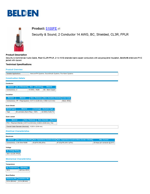
5100FE安全与声音产品说明书
Conductor(s) PP - Polypropylene 0.011 in (0.28 mm) 0.092 in (2.3 mm)
Black, White
Outer Shield
Shield Type
Material
Coverage Drainwire Type
Tape
Bi-Laminate (Alum+Poly) 100%
Belden provides the information and specifications herein on an "ASIS" basis, with no representations or warranties, whether express, statutory or implied. In no event will Belden be liable for any damages (including consequential, indirect, incidental, special, punitive, or exemplary damages) whatsoever, even if Belden has been advised of the possibility of such damages, whether in an action under contract, negligence or any other theory, arising out of or in connection with the use, or inability to use, the information or specifications described herein.
5100FE 0081000 Gray Reel
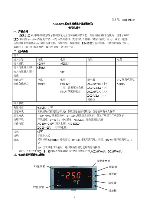
NHR-5100说明书
二、技术参数 备注:外形尺寸为、、的仪表继电器输出时允许负载能力为,。
版本号:5100-160112NHR -5100 系列单回路数字显示控制仪使用说明书一、产品介绍NHR -5100 系列单回路数字显示控制仪采用全自动贴片封装工艺,具有很强的抗干扰能力。
设计了双屏 LED 数码显示,显示内容更丰富。
可与各类传感器、变送器配合使用,实现对温度、压力、液位、速度、 力等物理量的测量显示,输出功能包括:报警控制、模拟变送、RS485/232 通讯等等,比传统的数显仪表还 新增加了还原出厂默认参数,操作更简便,适用更广泛。
三、仪表的显示面板和功能键 输入 输入信号 电流 电压 电阻电偶输入阻抗 ≤250Ω ≥500K Ω输入电流最大限制 ≤30mA输入电压最大限制 ≤6V 输出输出信号 电流 电压继电器24V 配电或馈电 输出负载能力≤500Ω≥250 K Ω(注:需要更高负载 能力时须更换模块)AC220V/0.6(小) DC24V/0.6A (小) AC220V/3A (大) DC24V/3A (大) 见备注 ≤30mA 综合参数 测量精度 0.2%FS ±1 字设定方式 面板轻触式按键数字设定;参数设定值密码锁定;设定值断电永久保存。
显示方式 -1999~9999 测量值显示,0~100%测量值光柱显示,发光二级管工作状态显示 使用环境 环境温度:0~50℃;相对湿度:≤85%RH ;避免强腐蚀气体工作电源 AC 100~240V (开关电源),(50-60HZ ); DC 20~29V (开关电源) 功耗 ≤5W结构 标准卡入式通讯采用标准 MODBUS 通讯协议,RS -485 通讯距离可达 1 公里,RS -232 通讯距离可达 15 米。
注:仪表带通讯功能时,通讯转换器最好选用有源转换器)仪表外形尺寸及开孔尺寸:外形尺寸开孔尺寸160*80mm(横式/光柱)152*76mm80*160mm(竖式/光柱)76*152mm96*96mm(方式/光柱)92*92mm96*48mm(横式)92*45mm48*96mm(竖式)45*92mm72*72mm(方式)68*68mm48*48mm(方式)45*45mm2PV显示窗:显示测量值;在参数设定状态下,显示参数符号SV显示窗:显示输入分度号、报警值等,可根据要求自行选择显示;在参数设定状态下,显示设定参数值。
莫加UC-5100系列IIoT网关产品介绍说明书

UC-5100SeriesArm Cortex-A81GHz IIoT gateways with1mini PCIe expansion slot for wireless module,4 serial ports,2CAN ports,4DIs,4DOsFeatures and Benefits•Armv7Cortex-A81000MHz processor•Dual auto-sensing10/100Mbps Ethernet ports•4software-selectable RS-232/422/485ports supporting all signals•Dual CAN ports with industrial CAN2.0A/B protocol supported•Moxa Industrial Linux with10-year long-term support•Mini PCIe socket for Wi-Fi/cellular module•SD slot for storage expansion•-40to85°C wide temperature range and-40to70°C with LTE enabled•IEC61000-6-2/6-4standards for harsh industrial environmentsCertificationsIntroductionThe UC-5100Series embedded computers are designed for industrial automation applications.The computers feature4RS-232/422/485full signal serial ports with adjustable pull-up/pull-down resistors,2CAN ports,2Ethernet ports,4digital input channels,4digital output channels,USB interface,and an SD slot in a compact,front-end access housing.To fulfill various industrial applications,the UC-5100Series computing platform provides models with2CAN ports and a mini PCIe slot for wireless connections featuring a dual-SIM design for network redundancy.The UC-5100’s vertical DIN-rail form factor makes it easy to install the computer in a small cabinet.This space-saving solution also facilitates easy wiring, making the UC-5100a great choice as front-end embedded controllers for industrial applications.Furthermore,all models are equipped with Moxa Industrial Linux that comes with10-year long-term support as well as optimized software features.Appearance UC-5101UC-5102UC-5111UC-5112SpecificationsComputerCPU Armv7Cortex-A81GHzPre-installed OS Linux Debian9kernel4.4(Moxa Industrial Linux) DRAM512MB DDR3Storage Pre-installed8GB eMMCStorage Slot SD slots x1Expansion Slots UC-5102-LX:mPCIe slots x1UC-5112-LX:mPCIe slots x1UC-5102-T-LX:mPCIe slots x1UC-5112-T-LX:mPCIe slots x1Computer InterfaceUSB2.0USB2.0hosts x1,type-A connectorsNumber of SIMs2SIM Format MicroSerial Ports RS-232/422/485ports x4,software selectable(RJ45)Digital Input DIs x4Digital Output DOs x4Buttons Reset button,DIP switch for serial and CAN port configuration Console Port RS-232(TxD,RxD,GND),RJ45output(115200,n,8,1) Ethernet InterfaceEthernet Ports Auto-sensing10/100Mbps ports(RJ45connector)x2 Magnetic Isolation Protection 1.5kV(built-in)Serial InterfaceSerial Ports4x RS-232/422/485Data Bits5,6,7,8Parity None,Even,Odd,Space,MarkStop Bits1,1.5,2Serial SignalsRS-232TxD,RxD,RTS,CTS,DTR,DSR,DCD,GNDRS-422Tx+,Tx-,Rx+,Rx-,GNDRS-485-2w Data+,Data-,GNDRS-485-4w Tx+,Tx-,Rx+,Rx-,GNDCAN InterfaceNo.of Ports UC-5111-LX:2UC-5111-T-LX:2UC-5112-LX:2UC-5112-T-LX:2Signals UC-5111-LX:CAN_L,CAN_H,CAN Signal GNDUC-5111-T-LX:CAN_L,CAN_H,CAN Signal GNDUC-5112-LX:CAN_L,CAN_H,CAN Signal GNDUC-5112-T-LX:CAN_L,CAN_H,CAN Signal GNDTerminator UC-5111-LX:N/A,120ohms(by DIP)UC-5111-T-LX:N/A,120ohms(by DIP)UC-5112-LX:N/A,120ohms(by DIP)UC-5112-T-LX:N/A,120ohms(by DIP)Digital InputsVoltage0to0.8VDC2.0to5.5VDCDigital OutputsCurrent Rating24mA per channelVoltage0to0.55VDC2.5to3.3VDCLED IndicatorsSystem Power x1System Ready x1LAN2per port(10/100Mbps)Serial2per port(Tx,Rx)CAN UC-5111-LX:2per port(Tx,Rx),UC-5112-LX:2per port(Tx,Rx),UC-5111-T-LX:2perport(Tx,Rx),UC-5112-T-LX:2per port(Tx,Rx)Wireless Signal Strength UC-5112-LX:Cellular/Wi-Fi x3UC-5102-LX:Cellular/Wi-Fi x3UC-5102-T-LX:Cellular/Wi-Fi x3UC-5112-T-LX:Cellular/Wi-Fi x3Physical CharacteristicsHousing MetalWeight600g(1.32lb)Dimensions57x136x100mm(2.24x5.35x3.94in)Installation DIN-rail mounting,Wall mounting(with optional kit)Power ParametersInput Voltage9to48VDCInput Current0.95A@9VDC,0.23A@48VDCPower Consumption11WEnvironmental LimitsOperating Temperature Standard Models:-10to60°C(14to140°F)Wide Temp.Models:Product only:-40to85°C(-40to185°F)With LTE accessory:-40to70°C(-40to158°F)With Wi-Fi accessory:-10to70°C(14to158°F)Storage Temperature UC-5101-LX:-20to70°C(-4to158°F)UC-5102-LX:-20to70°C(-4to158°F)UC-5111-LX:-20to70°C(-4to158°F)UC-5112-LX:-20to70°C(-4to158°F)UC-5101-T-LX:-40to85°C(-40to185°F)UC-5102-T-LX:-40to85°C(-40to185°F)UC-5111-T-LX:-40to85°C(-40to185°F)UC-5112-T-LX:-40to85°C(-40to185°F)Ambient Relative Humidity5to95%(non-condensing)Vibration2Grms@IEC60068-2-64,random wave,5-500Hz,1hr per axis(without USB devicesattached)Shock IEC60068-2-27Standards and CertificationsSafety UL60950-1,EN60950-1,IEC60950-1EMC EN55032/24,EN61000-6-2/-6-4EMI CISPR32,FCC Part15B Class AEMS IEC61000-4-2ESD:Contact:4kV;Air:8kVIEC61000-4-3RS:80MHz to1GHz:10V/mIEC61000-4-4EFT:Power:2kV;Signal:1kVIEC61000-4-5Surge:Power:2kV;Signal:1kVIEC61000-4-6CS:10VIEC61000-4-8PFMFGreen Product RoHS,CRoHS,WEEEReliabilityAlert Tools External RTC(real-time clock)Automatic Reboot Trigger External WDT(watchdog timer)MTBFTime UC-5101-LX:728,216hrsUC-5101-T-LX:728,216hrsUC-5102-LX:704,409hrsUC-5102-T-LX:704,409hrsUC-5111-LX:584,470hrsUC-5111-T-LX:584,470hrsUC-5112-LX:568,997hrsUC-5112-T-LX:568,997hrsStandards Telcordia(Bellcore)Standard TR/SR WarrantyWarranty Period5yearsDetails See /warrantyPackage ContentsDevice1x UC-5100Series computer Documentation1x quick installation guide1x warranty cardInstallation Kit1x DIN-rail kit(preinstalled)1x power jackCable1x RJ45-to-DB9console cableDimensionsOrdering InformationModel Name CPU RAM Storage Ethernet Serial CAN SD USB Mini PCIeOperatingTemp.UC-5101-LX1GHz512MB8GB24–11–-10to60°CUC-5102-LX 1GHz512MB8GB24–111(dual-SIMsocket)-10to60°CUC-5111-LX1GHz512MB8GB24211–-10to60°CUC-5112-LX 1GHz512MB8GB242111(dual-SIMsocket)-10to60°CUC-5101-T-LX1GHz512MB8GB24–11–-40to85°CUC-5102-T-LX 1GHz512MB8GB24–111(dual-SIMsocket)-40to85°CUC-5111-T-LX1GHz512MB8GB24211–-40to85°CUC-5112-T-LX 1GHz512MB8GB242111(dual-SIMsocket)-40to85°CAccessories(sold separately)Power AdaptersPWR-24270-DT-S1Power adapter,input voltage90to264VAC,output voltage24V with2.5A DC load Power CordsPWC-C7AU-2B-183Power cord with Australian(AU)plug,2.5A/250V,1.83mPWC-C7CN-2B-183Power cord with three-prong China(CN)plug,2.5A/250V,1.83mPWC-C7EU-2B-183Power cord with Continental Europe(EU)plug,2.5A/250V,1.83mPWC-C7UK-2B-183Power cord with United Kingdom(UK)plug,2.5A/250V,1.83mPWC-C7US-2B-183Power cord with United States(US)plug,10A/125V,1.83mWi-Fi Wireless ModulesUC-WiFi-USB802.11a/b/g/n/ac,2.4/5GHz Wi-Fi module with2each of M2and M2.5screwsCellular Wireless ModulesUC-LTE-CAT1-EU LTE cellular module with2M2and2M2.5mounting screws for EMEA bands1,3,7,8,20,28AUC-LTE-CAT1-AP LTE cellular module with2M2and2M2.5mounting screws for APAC bands1,3,5,8,9,18(26),19,28 UC-LTE-CAT4-CN LTE cellular module with2M2and2M2.5mounting screws for LTE(FDD)bands B1,B3,B8and LTE(TDD)bands B39,B40,B41(38)AntennasANT-WDB-ARM-0202plus ADP 2.4/5GHz omni-directional antenna,2/2dBi,RP-SMA-type(male)connectorANT-LTE-OSM-03-3m BK700-2700MHz,multi-band antenna,specifically designed for2G,3G,and4G applications,3m cable ANT-LTE-ASM-04BK704-960/1710-2620MHz,LTE omni-directional stick antenna,4.5dBiANT-LTE-ASM-05BK704-960/1710-2620MHz,LTE stick antenna,5dBiANT-LTE-OSM-06-3m BK MIMO Multiband antenna with screw-fastened mounting option for700-2700/2400-2500/5150-5850MHzfrequenciesDIN-Rail Mounting KitsDK-UC-5000DIN-rail mounting kit with screws for the UC-5000SeriesWall-Mounting KitsWM-UC-5000Wall-mounting kit with screws for the UC-5000Series©Moxa Inc.All rights reserved.Updated Dec11,2020.This document and any portion thereof may not be reproduced or used in any manner whatsoever without the express written permission of Moxa Inc.Product specifications subject to change without notice.Visit our website for the most up-to-date product information.。
菲尼克斯5100说明书
菲尼克斯5100说明书菲尼克斯现货FL WLAN 5100 菲尼克斯现货FL WLAN 5100 WLAN接入点/端/中继器MIMO 3x3:2WLAN 02.11a、b、g、n2.4 GHz/5 GHz3根外置天线2x RJ 45尺寸(宽度 x 高度 x 深度)40 mm x 109 mm x 109 mm尺寸说明高度含天线插座,不含天线电缆FL WLAN以太网端口适配器是一款经济型工业WLAN 适配器,可将兼容以太网的设备连接到WLAN网络。
该以太网端口适配器外形紧凑,坚固耐用,内置无线模块和天线。
该设备防护等级达IP65,可直接现场安装,通过带M12连接器的以太网电缆连接到自动化设备。
优势:可直接在集成到应用以太网端口适配器的主要应用领域安装快捷轻松安装在现场以太网端口适配器是一种简易解决方案,可轻松将带以太网接口的工业自动化设备连接到WLAN网络。
该设备防护等级达IP65,可直接现场安装,通过带M12连接器的以太网电缆连接到自动化设备。
优势:内置天线的紧凑型IP65模块用于以太网和电力传输的M12接口轻松安装在现场自动组态,调试更简单安全通过Mode按钮轻松组态使用Mode按钮,无需组态即可轻松快速地构建安全的点到点网络和小型网络。
此外,也可通过网络浏览器轻松组态。
通过AT命令进行高级设置轻松组态和控制FL EPA 2在WLAN EPA模块运行过程中,可通过控制器发出的简单AT命令对其进行自动组态和控制。
这样就可以通过移动系统的控制器根据位置对漫游过程(即接入点之间的转换)进行控制。
FL EPA产品一览特性FL EPA 2FL EPA 2 RSMAWLAN标准IEEE 02.11a/b/gIEEE 02.11 a/b/g频段和道(*依不同国家而定)2.4 GHz,1-11道5 GHz:36-140道(端)5 GHz:36-4道(接入点)2.4 GHz,1-11道5 GHz:36-140道(端)5 GHz:36-4道(接入点)大数据速率(总值)54Mbps54 Mbps大数据流量(净值)< 20 Mbps< 20 Mbps运行模式端(单端网桥、多端网桥)(微型接入点)两个FL EPA模块之间的无线网桥端(单端网桥、多端网桥)(微型接入点)两个FL EPA模块之间的无线网桥大传输功率2.4 GHz:17 dBm(包括天线)5 GHz:15 dBm(包括天线)2.4 GHz:17 dBm(包括天线)5 GHz:15 dBm(包括天线)天线数1(内置)1(外置),RSMA接口安装后的防护等级IP65IP65环境温度(工作)-30°C … 60°C … 65°C电源9 … 30 V DC,大1.7 W9 …30 V DC,大1.7 W特殊性能双无线板:WLAN和蓝牙双无线板:WLAN和蓝牙功能强大的WLAN IEEE 02.11n模块,通范围更广采用新标准和MIMO技术,扩展通范围该设备有*的无线号,并采用符合IEEE 02.11n标准的MIMO(多点输入,多点输出)多天线技术,可在长距离范围内实现稳定、高速且可靠的无线通。
长城电源技术规格书说明书
电源技术规格书(客户承认书)SPECIFICATION FOR APPROV AL客户/ CUSTOMER: 光电显示客户物料号/CUSTOMER NO.:长城型号/ MODEL NO.: XSP200WV42B长城料号/ P/N .: 5171915电源版本/ POWER REV.: V01日期/ DATE: 2020.02.27客户确认签字,盖章后请回传一份承认书给我司。
Please return to us on copy of “SPECIFICATION FOR APPROV AL”with your approved signature.中国长城科技集团股份有限公司电源事业部China Greatwall Technology Group Co., LTD. Power Supply Division深圳宝安区石岩镇宝石东路长城工业园Great wall Industry Park, Baoshi East Rd, Shiyan Country, Baoan, ShenzhenTEL: 0755--29519374 / 26639997 FAX: 0755--29519395/power变更记录目录总则 (2)1 电气特性 (2)1.1输入特性 (2)1.1.1输入基本特性 (2)1.1.2输入保护特性 (2)1.2 输出特性 (2)1.2.1输出基本特性 (2)1.2.2输出保护特性 (3)1.2.3负载/温度曲线图&负载/输入电压曲线图 (3)2 环境 (4)3 电磁兼容性 (4)4 安规 (4)5 可靠性 (4)6 特殊要求 (4)7 外观结构 (5)7.1电源尺寸 (5)7.2标签图 (6)8 包装 (6)8.1电源净重 (6)8.2包装图 (6)8.3包装运输实验 (7)9条形码label说明 (7)10 使用注意事项 (8)10.1开箱检查 (8)10.2使用原则 (8)10.3安全注意事项 (8)11 产品保修 (8)11.1保修期限 (8)11.2维修范围 (8)11.3限制条款 (9)12 备注 (9)总则该款产品为AC转DC电源,90~264Vac交流输入,单路直流隔离输出,输出总功率168W,通过CCC、CE、UL认证,符合欧盟RoHS指令。
TP5100中文数据手册
STDBY (引脚 14) :绿灯电池充电完成指 示端。 当电池充电完成时 STDBY 被内部开
关拉到低电平,表示充电完成。除此之外,
STDBY 管脚将处于高阻态。 :红灯充电中状态指示 CHRG (引脚 15) 端。当充电器向电池充电时, CHRG 管脚
被内部开关拉到低电平,表示充电正在进 行;否则 CHRG 管脚处于高阻态。
R R R R
PWR_ON-(引脚 6):电源切换控制引脚。 当芯片接电源时, PWR_ON- 被内部开关拉 到低电平,驱动 PMOS 导通,当芯片不接电 源时,PWR_ON-被内部开关拉到高电平为 BAT 端电池电压,驱动 PMOS 关断。此引 脚可以用于电源供电切换, 也可用作检测电 源上电建立是否正常。 GND(引脚 7) :电源地。 VS(引脚 8) :输出电流检测的正极输入端。 BAT(引脚 9) :电池电压检测端。将电池 的正端连接到此管脚。 VREG(引脚 10) :内部电源。VREG 是一个 内部电源, 它外接一个 0.1uF 旁路电容到地, 可以最大驱动 5mA。 TS(引脚 11) :电池温度检测输入端。将 TS 管脚接到电池的 NTC(负温度系数热敏 电阻)传感器的输出端。如果 TS 管脚的电 压小于 VREG 的 45%或者大于 VREG 电压 的 80%,意味着电池温度过低或过高,则充 电被暂停。如果 TS 直接接 GND,电池温度 检测功能取消,其他充电功能正常。
R
R S=0.067Ω
R
VCHRG VSTDBY
V TEMP-H
R
ICHRG =5mA
ISTDBY =5mA
V TEMP-L
R
Δ V RECHRG
R
V FLOAT -V RECHRG
WF-5100 系列纯正波电源用户手册说明书
51001000 Watt Pure Sine Wave Power Inverter,Users ManualDistributed in the USA and Canada by CHENG USA, INC.2021 Aeroplex Drive North. Elkhart, IN. 46514Phone: 574-294-8997, Fax: 547-294-86981. Important Safety Instructions1-1. General Safety Precautions1-1-1. Do not expose the WF-5100 series inverter to rain,snow,spray,bilge or dust.To reduce risk of hazard, do not cover or obstruct the5100 seriesventilation openings. Do not install the WF-Inverter in azero-clearance compartment. Overheating may result.1-1-2. To avoid a risk of fire and electric shock.Make sure that existing wiring is in good electrical condition; and that wire size is not5100 seriesunder sized.Do not operate the WF-inverter withdamaged or substandard wiring.1-1-3. This equipment contains components which can produce arcs or sparks.To prevent fire or explosion do not install in compartmentscontaining batteries or flammable materials or in locations whichrequire ignition protected equipment.This includes any spacecontaining generator, fuel tanks, or joints, fittings, or otherconnection between components of the fuel system.1-2. Precautions When Working with Batteries1-2-1. If battery acid contacts skin or clothing, wash immediately with soap and water. If acid enters eye, immediately flood eye with runningcold water for at least20minutes and get medical attentionimmediately.1-2-2. Never smoke or allow a spark or flame in vicinity of battery.1-2-3. Do not drop a metal tool on the battery. The resulting spark or short-circuit on the battery or other electrical part may cause anexplosion.1-2-4. Remove personal metal items such as rings, bracelets, necklaces, and watches when working with a lead-acid battery.A lead-acid battery produces a short-circuit current high enough toweld a ring or the like to metal, causing a severe burn.2-1. General InformationPlease read all instructions and cautionary marking on this manual before using WF - series Inverter . 51002. Functional CharacteristicsThe WF-5100 Series is a stand alone power inverter with AC run through and is suitable for use in RV, Marine and other applications where clean 115Vac voltage is required.As long as 115Vac utility power is applied to the inverter,115Vac flow through the inverter to appliances. Should 115Vac utility power be cut off, the inverter automatically switches itself to the invert mode providing clean 115Vac. Once the 115Vac utility power is reapplied the inverter switches itself back to the run through mode. Note: Battery must be in place for run through function to work.The WF-5100 Series Inverter is available with12Vdc input (WF-5110H, WF-5110G) or24Vdc input (WF-5120H, WF-5120G). Both have 115Vac 60Hz output.The WF-5100 Series Inverter is also available in two different versions of output wiring:Model: WF-5110H and WF-5120H are hard wired outputs.Model: WF-5110G and WF-5120G have GFCI Receptacles for outputs.This provides a safe and easy way to plug appliances directly into the inverter.2-2. FeaturesProduct :1000 Watt continuous output for electronic appliancesPure sine wave output (THD < 3%) to operate higher -end electronic Equipments . Built in 2 milliseconds transfer time.Built in advance microprocessor to make friendly interface with user .Dual AC GFCI outlets or hard wire AC connection model options .LCD display with all operation statusUL 458 approval and FCC class B .Protection :Battery over voltage and under voltage protections .Over temperature protection .Over load protectionShort Circuit protectionGround fault protection by GFCI receptacle .Reverse polarity protection .AC Output Fuse(15A/600VAC)For Over-Current Protection.This allows the transfer from utility power to invert power to be interruption free, protecting sensitive equipment.2-3. Electrical Performance3. Basically Descriptions3-1Mechanical drawingsHARDWIRE3-2-1. AC Output Fuse:3-2-3. Battery terminals :Connect 12V /24V batteries or other 12V /24V power sources .3-2-4. Connect chassis ground terminal to earth ..Remote port : Connect RJ -11 wiring with remote control unit .3-2-2CAUTION : Do Not Remove Covers.For Continued Fire Protection Replace Only With Specified Type AndRate Fuse. Turns Off The Power Switch Before Replacing Fuse.Refer Servicing To Qualified Personnel.Fuse Information:Manufacturer: LITTELFUSE INCModel Number: KLDR15Fuse Size: 10.3*38.1mm, Rating: 15A/600VAC3-3-1. V entilation :Do not obstruct , allows at least 2 to 3 inches of clearance for airflow . 3-3-2. AC input: Pass Through VoltagePlug into AC source directly: 120Vac, 60Hz, 12 Amps Max .POWERDISPLAYSELETE4. Installation4-1AC Safety Grounding:During the AC wiring installation, AC input and output grounding areconnected to the inverter. The AC input grounding must connect to theincoming grounding of your AC utility sources and the AC output groundingshould go to the grounding point for your loads. (for example, a distributionpanel ground bus ).Neutral Grounding (GFCI):The neutral conductor of the AC output circuit of the Inverter isAutomatically connected to the safety ground during inverter operation.This conforms to National Electrical Code requirements that derived ACsources separately (such as inverter and generators) have their neutralconductors tied to ground in the same way that the neutral conductor fromthe utility is tied to ground at the AC breaker panel.For models configured with a transfer relay, while AC utility powerspresenting and the Inverter is in bypass mode, this connection(neutral of the Inverter's AC output to input safety ground ) is notpresented so that the utility neutral is only connected to ground at yourbreaker panel,as required.4-2Ground Fault Circuit Interrupters (GFCI):Recreational Vehicles Installations (for North American approvals) will requireGFCI protection. All branch circuits connected to the AC output hard wireshould be GFCI protected. Additional electrical codes may require GFCIprotection of certain receptacles in residential installations.While the pure sine wave output of the Inverter is equivalent to thewaveform provided by utilities, compliance with UL standards requires us toUse only GENERAL PROTECHT GROUP INC, test and recommend specific GFCI.Type DG15 ground-fault circuit-interrupter receptacles.Or AMERICAN ELECTRIC DEPOT INC, Type G1501ground-fault circuit-interrupter receptacles. Other types may failto operate properly when connected to this unit.4-3 Hard -wire InstallationTo make AC wiring connections :4-3-1. The AC wiring compartment is located on the front panel of theWF -5110H/WF-5120H .Remove the AC wiring compartment cover to gain access to the AC output hard-wire(pigtails leads).4-3-2. Connect to the AC output wiring of the WF -5110H/WF-5120H AC outputhard-wire(pigtails leads) by using wire connectors, refer to the following: Wire length / gauge Line (L )Black Neutral (N )White Ground Green orBare copper Within 16 feet / AWG # 16~18 16 ~ 32 feet / AWG # 14~164-3-3. After wiring , double check and review all connections to make surethe wires are in correct position and all wires are secure .4-4 Making DC Wiring Connections :Following recommendations for connections between the battery cables and the DC input terminals on the Inverter . T he cables should be made of high quality copper wiring, also keep the cable length as short as possible.I f cables are not of adequate gauge (too small or too long ), theinverter performance will decrease. Please refer to the above chart for proper cable length and gauges. . Battery cable fusing --- A fuse is required by the National Electrical Code (NEC ) to protect the battery and cables , A UL listed DC rated slow blow fuse must be installed in positive battery cable , within 18 inches of the battery .AC output WiringCables should be of adequate gauge for the length of cable being used.WFCO recommends the following cables for an optimum inverter performance . Model NoWireAWG Inline Fuse WF -5110H,5110G# 4 100A WF -5120H,5120G # 6 50A5. Operation:To operate the WF-5100series Inverter, turn it on by using the ON/OFFswitch. The inverter is now ready to deliver AC power to your loads. If youare loading several appliances, turn them on separately after the inverterswitch is on,this process is to avoid the power inverter from delivering thestarting current all at once to the loads.5-1. Controls and indicators:The ON/OFF switch turns on/off the control circuit of the powerinverter. The WF-5100Inverter operates on input voltage ranges as follows:10to15.0VDC for12V models20to30.0VDC for24V modelsYellow LED - indicates battery back up status.Green LED - indicates AC input status.Red LED - indicates inverter failure.LCD Display - indicates operation status.Note: Inverter will not operate on AC input only. A battery must beconnected to the inverter for inverter to operate.6. Warranty Information6-1. WFCO Power Inverter :WFCO extends, to the original owner, a Limited Power Inverter Warrantycommencing from the original date of purchase for a period of two (2) years.This limited warranty is extended specifically for and is limited to RecreationalVehicle application and is only valid in the continental United States, Alaska,Hawaii and the Provinces of Canada. WFCO warrants, to the owner, that itsPower Inverter is free from defects in material and workmanship under normaluse and service based on its intended use and function and is limited to the repair or replacement, at its discretion, of any defective part or defective assembly. Any implied warranties of merchantability and fitness for intended use are limited induration unless applicable State Law provides otherwise. You may have otherright as specified by each individual state.6-2. Exclusions and limitations :The OEM warranty specifically does not apply to the following :Any Power Inverter that has been repaired or altered by anunauthorized person.Any damage caused by misuse, faulty installation, testing, negligence oraccident or any Power Inverter installed in a commercial vehicle.Any Power Inverter whose serial number has been defaced altered orremoved.Any consequential damages arising from the loss of use of the productincluding but not limited to : inconvenience, loss of service, loss of revenue,loss or damage to personal property, cost of all services performed inremoving or replacing the WFCO Power Inverter.6-3. Warranty:Upon determination and validation by the OEM dealer that a WFCO PowerInverter has a defect, the dealer shall contact the WFCO warranty servicenumber (877) 294-8997and obtain a return goods authorization (RGA) number.This number shall appear on all correspondence with warranty service.Upon validation warranty service shall replace the Power Inverter with alike product. The RGA number shall also be placed on the outside of the carton used to return the product for ease of identification. Do not mark on thePower Inverter.。
- 1、下载文档前请自行甄别文档内容的完整性,平台不提供额外的编辑、内容补充、找答案等附加服务。
- 2、"仅部分预览"的文档,不可在线预览部分如存在完整性等问题,可反馈申请退款(可完整预览的文档不适用该条件!)。
- 3、如文档侵犯您的权益,请联系客服反馈,我们会尽快为您处理(人工客服工作时间:9:00-18:30)。
Outer Shield
Outer Shield Material:
Outer Shield Trade Name Type Outer Shield Material Beldfoil® Coverage (%) Tape Aluminum Foil-Polyester Tape w/Shorting Fold 100
Capacitance (pF/ft) 97.250
Nom. Conductor DC Resistance:
DCR @ 20°C (Ohm/1000 ft) 2.54
Nominal Outer Shield DC Resistance:
DCR @ 20°C (Ohm/1000 ft) 10.000
Detailed Specifications & Technical Data
ENGLISH MEASUREMENT VERSION
5100FE Multi-Conductor - Commercial Audio Systems - 2 Conductors Cabled For more Information please call 1-800-Belden1
# Conductors AWG Stranding Conductor Material 2 14 19x27 BC - Bare Copper
Insulation
Insulation Material:
Insulation Material Wall Thickness (in.) PP - Polypropylene 0.011
Suitable Applications: Intercom/PA Systems, Sound/Audio Systems, Fire Alarm Systems (For color Red only)
Physical Characteristics (Overall)
Conductor
AWG:
Description: 14 AWG bare copper conductors, PP insulation, conductors cabled, Beldfoil® shield tape (foil side out) with drain wire, PVC jacket with ripcord, sequential footage marking every two feet. Usage (Overall)
Outer Shield Drain Wire AWG:
AWG Stranding Drain Wire Conductor Material 22 7x30 TC - Tinned Copper
Outer Jacket
Outer Jacket Material:
Outer Jacket Material Nom. Wall Thickness (in.) PVC - Polyvinyl Chloride 0.017
Flame Test
UL Flame Test: CSA Flame Test: UL1666 Vertical Shaft FT4
Plenum/Non-Plenum
Plenum (Y/N): Plenum Number: No 6100FE
Electrical Characteristics (Overall)
Max. Operating Voltage - UL:
Voltage 300 V RMS
Max. Recommended Current:
Current 8 Amps per conductor Nhomakorabea@ 25°C
Put Ups and Colors:
Item # 5100FE 0021000 5100FE 008U1000 Putup 1,000 FT 1,000 FT Ship Weight 39.000 LB 39.000 LB Color RED GRAY Notes C Item Desc 2 #14 PP FS FRPVC 2 #14 PP FS FRPVC
Outer Jacket Ripcord:
Yes
Overall Cabling
Overall Cabling Lay Length & Direction:
Length (in.) 2.75
Overall Cabling Color Code Chart:
Number Color 1 2 Black White
Revision Date: 06-16-2008
Although Belden makes every reasonable effort to ensure their accuracy at the time of this publication, information and specifications described herein are subject to error or omission and to change without notice, and the listing of such information and specifications does not ensure product availability. Belden provides the information and specifications herein on an "AS IS" basis, with no representations or warranties, whether express, statutory or implied. In no event will Belden be liable for any damages (including consequential, indirect, incidental, special, punitive, or exemplary damages) whatsoever, even if Belden has been advised of the possibility of such damages, whether in an action under contract, negligence or any other theory, arising out of or in connection with the use, or inability to use, the information or specifications described herein. All sales of Belden products are subject to Belden's standard terms and conditions of sale. Belden believes this product to be in compliance with EU RoHS (Directive 2002/95/EC, 27-Jan-2003). Material manufactured prior to the compliance date may be in stock at Belden facilities and in our Distributor’s inventory. The information provided in this Product Disclosure, and the identification of materials listed as reportable or restricted within the Product Disclosure, is correct to the best of Belden’s knowledge, information, and belief at the date of its publication. The information provided in this Product Disclosure is designed only as a general guide for the safe handling, storage, and any other operation of the product itself or the one that it becomes a part of. This Product Disclosure is not to be considered a warranty or quality specification. Regulatory information is for guidance purposes only. Product users are responsible for determining the applicability of legislation and regulations based on their individual usage of the product. Belden declares this product to be in compliance with EU LVD (Low Voltage Directive 73/23/EEC), as amended by directive 93/68/EEC.
Overall Nominal Diameter:
0.222 in.
Mechanical Characteristics (Overall)
Operating Temperature Range: UL Temperature Rating: Bulk Cable Weight: -20°C To +75°C 75°C 45.800 lbs/1000 ft. Page 1 of 3 11-26-2008
Nom. Inductance: