HART手操器菜单中英文对照
DVC6000(Hart)系列菜单树(中英文对照20110928)基本词语

A
B
C
D
E
F
G
H
I
Tvl Alrt Hi Hi Enab Tvl Alrt Lo Lo Enab Tvl Alrt Hi Hi Pt Tvl Alrt Lo Lo Pt Tvl Alrt Hi Enab Tvl Alrt Lo Enab
Tvl Alrt Hi Pt Tvl Alrt Lo Pt Tvl Limit/Cutoff Hi Alrt Enab Tvl Limit/Cutoff Lo Alrt Enab Tvl/Press Cut Hi Tvl/Press Cut Lo Tvl Limit Hi Tvl Limit Lo Tvl Dev Alrt Enab Tvl Dev Alrt Pt
Tvl Dev Time
指定电压关闭
非空闲时间关闭闪存关闭重要非易失性存储器关闭激活行程偏差报警
激活行程偏差报警点行程偏差时间激活行程高高报激活行程低低报行程低低报点行程高高报点激活行程高报
激活行程低报行程高报点行程低报点
激活行程限定/截断高报激活行程限定/截断低报行程压力截止高报行程压力截止低报行程限定高报行程限定低报
激活非重要非易失性存储器报警。
hart475手操器中文说明书
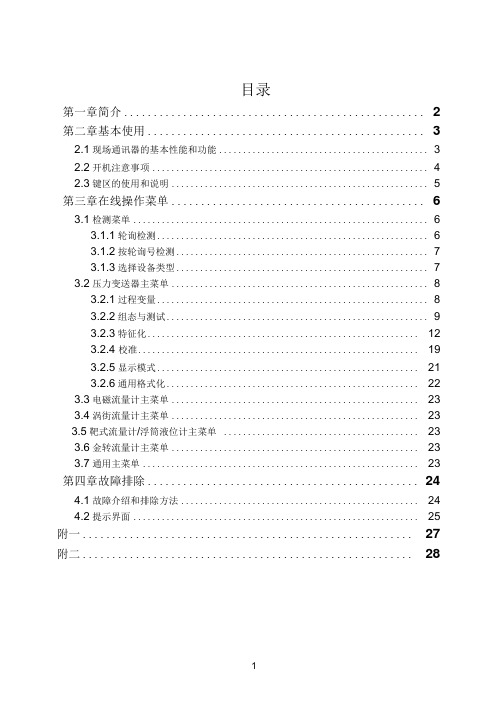
目录第一章简介 (2)第二章基本使用 (3)2.1现场通讯器的基本性能和功能 (3)2.2开机注意事项 (4)2.3键区的使用和说明 (5)第三章在线操作菜单 (6)3.1检测菜单 (6)3.1.1轮询检测 (6)3.1.2按轮询号检测 (7)3.1.3选择设备类型 (7)3.2压力变送器主菜单 (8)3.2.1过程变量 (8)3.2.2组态与测试 (9)3.2.3特征化 (12)3.2.4 校准 (19)3.2.5显示模式 (21)3.2.6通用格式化 (22)3.3电磁流量计主菜单 (23)3.4涡街流量计主菜单 (23)3.5靶式流量计/浮筒液位计主菜单 (23)3.6金转流量计主菜单 (23)3.7通用主菜单 (23)第四章故障排除 (24)4.1故障介绍和排除方法 (24)4.2提示界面 (25)附一 (27)附二 (28)第一章简介感谢您使用本现场通讯器,本通讯器适合HART协议智能变送器的通讯操作,与HART275、HART388、HART375兼容,具有极好的兼容性,可通讯1151, 3051,EJA,ABB及流量方面的HART协议的进口仪表。
完全兼容国产的各种HART协议智能变送器。
该手册介绍了现场通讯器基本的使用、连接和操作方面的内容以及故障的排除和在使用过程中应该注意的事项。
在使用本现场通讯器之前,请阅读该该操作手册,为了更好发挥该产品的最佳性能,在使用或维修本产品之前,请深入掌握相应的内容。
如若设备需要维修,请联系我们公司。
我们将竭尽所能为您服务。
手操器电池(机内)包充电器通讯线缆操作手册250欧姆电阻一.台一块一个一部一条一本一支该设备配备:第二章基本使用2.1现场通讯器的基本性能和功能现场通讯器示图2.2开机注意事项在开机前,请确保以下几点:-该现场通讯器没有物理机械损坏-电池已充满电。
-将现场通讯器连接到回路(如图2-2)-回路中串有250欧姆的电阻图:图2-2启动现场通讯器在启动前请保证该设备已充好电。
Hart475菜单中英文对照高清版演示教学

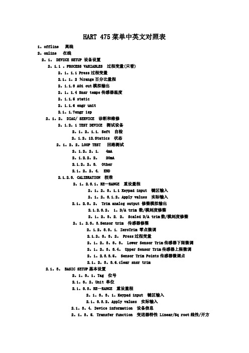
精品文档精品文档Hart475菜单中英文对照 1. PROCESS VARIABLES 过程变量(只看) 1. Press过程变量 2. %range百分比量程 3. AO1 out模拟输出 4. Snsr tempe传感器温度 5. static 6.engr unit 7.engr disp1. TEST DEVICE 测试设备 1. Seft 自检2. Statics 状态2. DIAG/ SERVICE 2. LOOP TEST 回路测试 1. 4mA 2. 20mA3. Other4. END诊断和维修 1.RE-RANGE 重设量程( 1.Keypad input 键区输入 2.Apply values 实际输入)3.CALIBRATION 校准 2. Trim analog output 修整模拟输出( 1.D/A trim 数/模刻度修整 2. Scaled D/A trim数/模刻度修整)3.Sensor trim 传感器修整 1. ZeroTrim 零点微调 2. Press过程变量 3. Lower Sensor Trim传感器下限微调1.Tag 位号 4. Upper Sensor Trim传感器上限微调 5. Sensor Trim Points传感器微调点 6.clear snsr trim2.Unit 单位3.RE-RANGE 重设量程( 1.Keypad input 键区输入 2.Apply values 实际输入)3. BASIC SETUP4. Device information 设备信息基本设置 5.Transfer function 变送器特性Linear/Sq root线性/开方6.Damp 阻尼7.Low cut 1. %range百分比量程8.cut mode 2. Press过程变量1.PRES SENSOR压力传感器 3. Unit 1. ZeroTrim 零点微调2. Press过程变量3. Lower Sensor Trim传感器下限微调1. DEVICE SETUP 设备设置 1. SENSORS传感器 4. Sensor trim 传感器修整 4. Upper Sensor Trim传感器上限微调 5. Sensor Trim Points传感器微调点 6.clear snsr trim1.offline 离线2. Pres 压力 2. TEMP SENSOR传感器温度(1.Sensor Temp 传感器温度 2. Amp temp3.snsr temp unit )2.online 在线3. AO1 out 模拟输出4. DETAILED SETUP 3. Statics pres Sensor (1.Statics pres 2.Statics pres unit )3.utility4. LRV 量程下限详细设置 1.Process variables 过程变量 2. RE-RANGE 重设量程 3. Unit 单位 4. Transfer function 变送器特性Linear/Sq root线性/开方4.Hart Diagnostics 诊断5. URV 量程上限 2. SIGNAL CONDITION信号条件 5. Damp 阻尼6. Low cut7. cut mode8.Bi-dir mode9.H2O cutliselect1. PROCESS VARIABLES (1. Press过程变量2. %range百分比量程3. AO1 out模拟输出4. Snsr tempe传感器温度5. static6.engr unit7.engr disp)过程变量精品文档精品文档3. OUTPUT CONDITION输出条件 2. ANALOG OUTPUT 1.Loop test回路测试(4mA 20mA Other END) 2. D/A trim 数/模刻度修整 3. Scaled D/A trim数/模刻度修整(1.proceed 2.change )模拟输出 4.Auto recover 5.AO Lower Limit% 5.AO Upper Limit%3. AO1 Alarm type 模拟输出报警类型4. HART OUTPUT Hart 输出(1.Poll Address波尔地址2.Number request preambles 需求号码 3. Burst mode突发模式 4.Burst option突发选项)1. Display mode (1.Normal%er set3. User set &%4.Input press5.Input press &% )4.Display condition 2. Display fnctn3.Engr disp range1. FIELD DEVICE INFO现场设备信息 1.Tag位号2.Date日期3.Descriptor描述4.Message信息5.Model型号6.Write protect写保护5. DEVICE INFORMATION 7.Local Keys 本机键(ENABLE-允许DISABLE-禁止)8.Revision 9.Final assy #--Device ID设备信息 1. Measurement Type 测量类型 2. mod. Config. Type 模块组态类型3 .Isolator Material 隔离器材质 4. Fill Type 法兰类型2.SENSOR INFO传感器信息 5 .Proc. Conn. Type 过程连接类型 6. Proc. Conn. Materia 过程连接材质7 .O-Ring Material 模片材质8. Drain/Vent Material 排液/排气材质3. SELF TEST 自检1.Manufacturer2.Model3.Unit4.LSL5. USL5. Review审核6.Min span7.LRV8.URV。
475菜单中英文对照表---精品管理资料
HART 475菜单中英文对照表1。
offline 离线2。
online 在线2。
1。
DEVICE SETUP 设备设置2。
1.1 。
PROCESS VARIABLES 过程变量(只看)2。
1。
1.1 Press过程变量2.1。
1。
2 %range百分比量程2。
1.1.3 AO1 out模拟输出2。
1。
1.4 Snsr tempe传感器温度2。
1.1.5 static2。
1.1.6 engr unit2.1。
1.7engr isp2。
1。
2。
DIAG/ SERVICE 诊断和维修2。
1.2。
1 TEST DEVICE 测试设备2。
1。
2。
1.1. Seft 自检2。
1.2。
12.Statics 状态2。
1。
2。
2。
LOOP TEST 回路测试2。
1.2。
2。
1. 4mA2。
1.2.2。
2。
20mA2.1.2。
2。
3. Other2.1。
2。
2。
4. END2.1.2.3. CALIBRATION 校准2。
1。
2.3.1。
RE—RANGE 重设量程2。
1。
2。
3。
1.1 Keypad input 键区输入2。
1。
2。
3.1.2。
Apply values 实际输入2.1。
2.3。
2。
Trim analog output 修整模拟输出2.1.2.3.2。
1。
D/A trim 数/模刻度修整2。
1。
2。
3。
2. 2。
Scaled D/A trim数/模刻度修整 2。
1。
2.3。
3.Sensor trim 传感器修整2。
1.2。
3.3。
1. ZeroTrim 零点微调2.1.2。
3。
3。
2。
Press过程变量2。
1。
2。
3。
3。
3。
Lower Sensor Trim传感器下限微调2。
1。
2。
3。
3.4。
Upper Sensor Trim传感器上限微调2。
1。
2.3.3.5。
Sensor Trim Points传感器微调点2.1。
2。
3。
3.6.clear snsr trim2.1。
3。
hart475横河eja菜单中英文对照(1)

过程变量(只看) 1. Press过程变量 2. %range百分比量程 3. AO1 out模拟输出 4. Snsr tempe传感器温度 5. static unit工程单位 disp工程显示1. TEST DEVICE 测试设备 1. Seft 自检2. Statics 静态2. DIAG/ SERVICE 2. LOOP TEST 回路测试 1. 4mA 2. 20mA3. Other4. END诊断和维修重设量程 ( input 键区输入 values 实际输入 )校准 2. Trim analog output 数/模刻度修整 2. Scaled D/A trim数/模刻度修整)传感器修整 1. ZeroTrim 零点微调 2. Press过程变量 3. Lower Sensor Trim传感器下限微调位号 4. Upper Sensor Trim传感器上限微调 5. Sensor Trim Points传感器微调点 snsr trim单位重设量程 ( input 键区输入 values 实际输入 )3. BASIC SETUP4. Device information 设备信息基本设置 5. Transfer function 变送器特性 Linear/Sq root线性/开方6. Damp 阻尼cut 1. %range百分比量程mode 2. Press过程变量SENSOR压力传感器 3. Unit 1. ZeroTrim 零点微调 2. Press过程变量 3. Lower Sensor Trim传感器下限微调1. DEVICE SETUP 1. SENSORS传感器传感器修整 4. Upper Sensor Trim传感器上限微调 5. Sensor Trim Points传感器微调点 snsr trim离线 2. Pres 压力 2. TEMP SENSOR传感器温度 Temp 传感器温度 2. Amp temp temp unit )在线 3. AO1 out 模拟输出 4. DETAILED SETUP 3. Statics pres Sensor pres pres unit )4. LRV 量程下限详细设置 variables 过程变量 2. RE-RANGE 重设量程 3. Unit 单位 4. Transfer function 变送器特性 Linear/Sq root线性/开方Diagnostics 诊断 5. URV 2. SIGNAL CONDITION信号条件 5. Damp 阻尼 6. Low cut 7. cut mode mode cutliselect1. PROCESS VARIABLES (1. Press过程变量2. %range百分比量程3. AO1 out模拟输出4. Snsr tempe传感器温度5. static unit disp)过程变量3. OUTPUT CONDITION输出条件 2. ANALOG OUTPUT test回路测试(4mA 20mA Other END) 2. D/A trim 数/模刻度修整 3. Scaled D/A trim数/模刻度修整 )模拟输出 recover Lower Limit% Upper Limit%3. AO1 Alarm type 模拟输出报警类型4. HART OUTPUT Hart 输出 Address波尔地址 request preambles 需求号码 3. Burst mode突发模式 option突发选项)1. Display mode % set 3. User set &% press press &% )condition 2. Display fnctndisp range1. FIELD DEVICE INFO现场设备信息位号日期描述信息型号 protect写保护5. DEVICE INFORMATION Keys 本机键(ENABLE-允许 DISABLE-禁止) assy #--Device ID设备信息 1. Measurement Type 测量类型 2. mod. Config. Type 模块组态类型3 .Isolator Material 隔离器材质法兰类型INFO传感器信息 5 .Proc. Conn. Type 6. Proc. Conn. Materia 过程连接材质7 .O-Ring Material 模片材质排液/排气材质3. SELF TEST 自检5. USL5. Review审核span。
HART手操器菜单中英文对照

HART手操器(智能型)、压力pres、量程百分比% rnge3、模拟输出Ao1、自检self test2、状况status 1、键盘输入keypad input1、重定量程Re—2、提供压力值apply values、数/模转换调整D/A trim2、调整模拟输出、校准2、刻度的数/模转换调整scaled D/A trim1、零点调整zero trim32、传感器下限调整lower sensor trimsensor trim 3、传感器上限调整upper sensor trim4、传感器调整点sensor trim points、工位号tag 1、键盘输入keypad input2、单位unit、量程值、提供压力值Apply values1、日期date2、描述符descriptor3、信息message4、写保护write protect5、表头类型meter type传送功能x fer fnctn linear阻尼damp过程变量process variables传感器传感器维修senson servin单位unit 压力pres过程变量% rngekeypad input单位unit apply values detailed setup x fer fnctn lineardamp 、压力pres、过程变量2、量程百分比% rnge3、模拟输出Ao1、回路测试loop test、模拟输出2、数/模转换调整D/A trim、模拟输出报警、刻度的数/模转换调整scaled D/A trim查询poll address、HART输出2请求起始码数目num rea preams、突发模式burst mode1、突发模式选择burst option1、日期datereview 、描述符descriptor3、表头类型、信息message5、型号model、自检6、写保护write protecttest 7、版本号revisior1、测量类型means type gage、传感器信息、隔离膜片材料Isoltor matl3、充液类型fill fluid4、法兰类型flange type5、法兰材料flange matl6、O—型环材料o-ring matl7、排气/排液阀材料drain vent matl8、远传数量final asmbly number9、远传类型devid。
Hart475横河EJA菜单中英文对照
Hart475横河EJA菜单中英文对照1. PROCESS VARIABLES 过程变量(只看) 1. Press过程变量2. %range百分比量程3. AO1 out模拟输出4. Snsr tempe传感器温度5. static6.engr unit工程单位7.engr disp工程显示1. TEST DEVICE 测试设备 1. Seft 自检2. Statics 静态2. DIAG/ SERVICE 2. LOOP TEST 回路测试 1. 4mA 2. 20mA3. Other4. END诊断和维修1.RE-RANGE 重设量程( 1.Keypad input 键区输入2.Apply values 实际输入)3.CALIBRATION 校准2. Trim analog output 修整模拟输出( 1.D/A trim 数/模刻度修整 2. Scaled D/A trim数/模刻度修整)3.Sensor trim 传感器修整 1. ZeroTrim 零点微调 2. Press过程变量 3. Lower Sensor Trim传感器下限微调1.Tag 位号 4. Upper Sensor Trim传感器上限微调 5. Sensor Trim Points传感器微调点 6.clear snsr trim2.Unit 单位3.RE-RANGE 重设量程( 1.Keypad input 键区输入 2.Apply values 实际输入)3. BASIC SETUP4. Device information 设备信息基本设置 5. Transfer function 变送器特性Linear/Sq root线性/开方6. Damp 阻尼7.Low cut 1. %range百分比量程8.cut mode 2. Press过程变量1.PRES SENSOR压力传感器 3. Unit 1. ZeroTrim 零点微调2. Press过程变量3. Lower Sensor Trim传感器下限微调1. DEVICE SETUP 1. SENSORS传感器 4. Sensor trim 传感器修整 4. Upper Sensor Trim传感器上限微调 5. Sensor Trim Points传感器微调点 6.clear snsr trim1.offline 离线2. Pres 压力 2. TEMP SENSOR传感器温度(1.Sensor Temp 传感器温度 2. Amp temp3.snsr temp unit )2.online 在线3. AO1 out4. DETAILED SETUP 3. Statics pres Sensor (1.Statics pres2.Statics pres unit )3.utility4. LRV 详细设置 1.Process variables 过程变量 2. RE-RANGE 重设量程 3. Unit 单位 4. Transfer function 变送器特性Linear/Sq root 线性/开方4.Hart Diagnostics 诊断5. URV 2. SIGNAL CONDITION信号条件 5. Damp 阻尼6. Low cut7. cut mode8.Bi-dir mode9.H2O cutliselect1. PROCESS VARIABLES (1. Press过程变量2. %range百分比量程3. AO1 out模拟输出4. Snsr tempe传感器温度5. static6.engr unit7.engr disp)过程变量3. OUTPUT CONDITION输出条件 2. ANALOG OUTPUT 1.Loop test回路测试(4mA 20mA Other END) 2. D/A trim 数/模刻度修整 3. Scaled D/A trim数/模刻度修整(1.proceed 2.change )模拟输出 4.Auto recover 5.AO Lower Limit% 5.AO Upper Limit%3. AO1 Alarm type 模拟输出报警类型4. HART OUTPUT Hart 输出(1.Poll Address波尔地址2.Number request preambles 需求号码3. Burst mode突发模式 4.Burst option突发选项)1. Display mode (1.Normal%er set3. User set &%4.Input press5.Input press &% )4.Display condition 2. Display fnctn3.Engr disp range1. FIELD DEVICE INFO现场设备信息 1.Tag位号2.Date日期3.Descriptor描述4.Message信息5.Model型号6.Write protect写保护5. DEVICE INFORMATION 7.Local Keys 本机键(ENABLE-允许DISABLE-禁止)8.Revision 9.Final assy #--Device ID设备信息 1. Measurement Type 测量类型 2. mod. Config. Type 模块组态类型3 .Isolator Material 隔离器材质 4. Fill Type 法兰类型2.SENSOR INFO传感器信息 5 .Proc. Conn. Type 过程连接类型6. Proc. Conn. Materia 过程连接材质7 .O-Ring Material 模片材质8. Drain/Vent Material 排液/排气材质3. SELF TEST 自检1.Manufacturer2.Model3.Unit4.LSL5. USL5. Review审核6.Min span7.LRV8.URV。
HART 手操器英文说明书
FIELD COMMUNICATORJIANGSU BOOST INSTRUMENT SCIENCE AND TECHNOLOGY CO.,LTDCHAPTER Ⅰ Introduction (2)CHAPTER Ⅱ Basic use (3)2.1 Field communicator basic performance and functions (3)2.2 Power Considerations (4)2.3 Key areas of use and instructions (5)CHAPTER Ⅲ menu online operation3.1 Test menu (6)3.1.1 Always poll (6)3.1.2 Ask before polling (7)3.1.3 Select the type (7)3.2 PRESS TRANS MAIN MENU (8)3.2.1 Process variables (8)3.2.2 Diagnostics and service (9)3.2.3 Characterization (11)3.2.4 Calibration (17)3.2.5 Display mode (19)3.2.6 General format (20)3.3 ELECTROMAGNETIC FLOWMETER MAIN MENU (20)3.4 VORTEX FLOWMETER MAIN MENU (20)3.5 FARGET FLOWMETER/ FLOAT LEV GAUGE MAIN MENU (20)3.6 METAL ROTAMETER MAIN MENU (20)3.7 GENERAL MAIN MENU (21)CHAPTER Ⅳ Troubleshooting (21)4.1 Description and remedy fault (21)4.2 Windows for warning (22)Appendix I (24)Appendix II (25)Appendix Ⅲ (31)CONTENTSCHAPTER Ⅰ IntroductionThank you for using HART475 Field Communicator, Communicator for the HART Communication protocol smart transmitter operation, and HART275, HART375,HART475 compatible with excellent compatibility, communication 1151,3051,EJA, ABB and flow aspects of the HART protocol imported instruments. Completely and yung made a variety of smart transmitters.The manual describes the basic use of field communication device, connection and operation in Content as well as troubleshooting and in the course should pay attention.Field Communicator using the HART475, please read the manual, In order to better play to the best performance of the product in use or maintenance of the product Before understanding of the appropriate content.Should the equipment needs repair, please contact our company. We will do our best to for you.The device is equipped with:a manual operatorBattery aPack aA chargerA communication cableManual aA 250 ohm resistorCHAPTER Ⅱ Basic use2.1 Field communicator basic performance and functionsCommunicatecableBatterydisplayDisplayFourkeysnavigationPV KeyEnterON/OFFAlphanumeric keypadCharger connectorLeft -right selectionkeyField Communicator2.2 Power ConsiderationsIn turn, ensure the following:* The Field Communicator is no mechanical damage* Battery is fully charged.* The Field Communicator to connect to the circuit (Figure 2-2) * String loop resistance of 250 ohms+··Power —+-Figure 2-2Start Field CommunicatorBefore starting to ensure that the device is fully charged. Start holding down the power key until To the bright LCD screen, a successful boot.CloseSuch as to close the Field Communicator, hold the key to open up their show off, shutdown complete.2.3 Key areas of use and instructionsOpen keyThe key is used to enable or disable the Field Communicator. Arrow navigation keysFour navigation arrow keys provide menu options. Press the right arrow navigation key to enter a menu of specific options. Press Left navigation key to return to the previous menu, up and down navigation keys can be cut down in the menu Change. In the character input mode digital down navigation keys can be used as a backspace key. EnterAfter entering the menu, you can modify the contents of the LCD's bottom Line will automatically display the "Edit" to modify the words For you press the Enter key, the change was successful.Alphanumeric keyboardCharacter numeric keypad to enter characters, numbers and other symbols, numbers, and he has Characters in both input modes, field communication device according to the need to select the appropriate input mode.To enter numbers, press the number directly to where the keys to enter characters, according to the word Character position on the keyboard, first pressA key, then press the characterkey is located. For example, to enter the character "A", the first Press the left selection key, then press the number 1 character keyboard.PV keyMonitoring real-time variable shortcuts, view real-time pressure, current, percentage, Temperature, frequency and other real-time variable. Digital input mode, the character, the key is invalid.CHAPTER Ⅲ menu online operation3.1 Detection menuHow to poll:2.Ask Bef PollFigure 3-13.1.1 Polling DetectionSelect the menu, Field Communicator polling numbers from the polling numbers from 0 to 15 followed by detection equipment, if detected, the device will automatically detect the transmitter and the station number(Figure 3-1-1), press the right navigation key to enter the device type selection menu (Figure3-1-2); if not Have detected the device does not detect the transmitter will appear warning.TRANS detected:TAG No[DS8001]Figure 3-1-13.1.2 Detection by poll numbersSpecified number of polling devices to detect, according to the up and down navigation keys Choose between 0 to 15 polling numbers, then press the right navigation key to start the test (test results If the same as Figure 3-1-1).3.1.3 Select Device Type1. Pressure Transmitter2 electromagnetic flowmeter3. Vortex Flowmeter4. Target Flowmeter / float level gauge5. Turn meter gold6 General menuSelect the type:2.Electromagnetic Flow meter3.Vortex Flowmeter4.Target Flowmeter / FloatLEV gauge5.Metal Rotameter6. General MenuWhen choosing the type of equipment must be selected according to the type of field device into a specific menu, if you select the type does not match the actual type, will cause an error. If the site becomes non-pressure equipment, electromagnetic, vortex, target-style, gold transfer device is connected into the general menu. Press the down navigation key to select the device type, then press the right navigation key to enter the selected device type detection, and enter the corresponding menu, if you select the type does not match with the test will be prompted.3.2 Pressure Transmitter Main MenuSubmenu1 Process Variable2 Configuration and testing3 Characterization4 Calibration Main menu:2.DIAG and Service 3.Characterization5 Display Modes6 common formatFigure 3-2-13.2.1 Process VariableReal-time display of pressure transmitter, the percentage of current, temperature and other parameters (Figure 3-2-2). Press the left navigation button for 3 seconds before the bounce out of real-time variable monitoring model.PRESS AO PC –0.2584.8205.127KpamA%TEMP 19.570 ℃3.2.2 Configuration and TestingDIAG and Service 2.Loop Test Submenu:1. Equipment Testing2. Loop test3. Basic Settings4. User range3.Basic setup Figure 3-2-3 3.2.2.1 Test equipmentTesting equipment status, if everything is normal, liquid crystal display "device normal", if wrong, will be a warning.3.2.2.2 Loop TestDetection of the D / A current output. First, a series ammeter in the circuit, and then type a 4-20mA current between the values into the transmitter, the transmitter will automatically output the current value type, if the type of value and ammeter display values are not equal, current fine-tuning to be done.3.2.2.3 Basic SettingsSubmenu:1. Unit2. Write Protect3. DampBasic Setup 2.Write Protect 3.Damping 4. Output5. Device Information6. Polling numbersFigure 3-2-4 UnitChange the primary variable units and display units. Provide MPa, Kpa, Pa, InH2O, InHg, psi, g / cm ², kg / cm ², FtH2O, torr,ATM, mmH2O, mmHg, Bar, mBar these 15 units. When the unit of measure on behalf of the Not recognize the number will automatically display "No" means that the unit "unknow". Repair Change methods, see the menu tree.Write ProtectRead-write device protection status, when the write-protected, the transmitter can not change the internal data. DampRead-write device damping coefficient (rounded to three decimal places). Seconds.OutputRead-write device output. Divided into linear, square root, and the unknown. The default is linear.Device InformationRead and write tag number, date, descriptor, message, final assembly numberPolling numbers3.2.2.4 User rangeUser Range2.Provide pressureFigure 3-2-5Keyboard inputSelect this menu, the first prompt sensor range, then enter the range of the setup menu, press the down navigation key to select zero or range, then enter the user needs to set the value (rounded to three decimal places), then press the right navigation key into the transmitter.Sensor Range L –180.000KPa H 180.000KPa User RangeL –180.000KPa H 180.000KPaFigure 3-2-6 Figure 3-2-7Provide pressure valuesPressure on the current value with the transmitter zero and span settings, press the up and down navigation keys, press the right navigation key to confirm.Provide Pressure2.RangeFigure 3-2-83.2.3 CharacterizationSubmenu:1 .Sensor trim2. Sensor measuring range3 user range4.K coefficient5 Formatting Characterization 2.Sensor range 3.User range6 small-signal removal7 Device Address8. Data Backup9. Data RecoveryThe menu will seriously affect the operation of the transmitter to work and accuracy, so enter this menu, you need to enter the authentication password (Figure 3-2-10).Please input password:******Figure 3-2-10The default password is: 6666663.2.3.1 Sensor trimSensor Trim2.Low Range Trim3.High Range TrimFigure 3-2-11Zero trimAfter the pressure transmitter with 0 to select this operation, the transmitter automatically adjust zero.Low fine-tuningTo increase low-pressure transmitter (in KPa), type the applied pressure values (rounded to three decimal places), thetransmitter automatically corrected, so that the output value of the applied pressure.High-end fine-tuningTo the transmitter plus high pressure (in KPa), type the applied pressure values (rounded to three decimal places), the transmitter automatically corrected, so that the output value of the applied pressure.3.2.3.2 Sensor RangeSensor Range2.Madify rangeFigure 3-2-12Select the rangeFirst select the type of sensor, and then select the range of the sensor code, then press the Enter key into the transmitter. (Figure 3-2-13,3-2-14)Sensor type Range Code[DP ][5]Figure 3-2-14Figure 3-2-13Modify RangeFirst select the range sensor code, then enter the code in the range of the scale. Note: The input pressure is measured in Pa, can only enter a positive integer. Change and then select the sensor range.3.2.3.3 User rangeKeyboard inputSelect this menu, the first prompt sensor range, then enter the range of the setup menu, press the up and down navigation key to select zero or range, then enter the user needs to set the value (rounded to three decimal places), enter and press the right navigation key to send into the transmitter.Sensor Range User RangeL –180.000KPa H 180.000KPa L –180.000KPaH 180.000KPaFigure 3-2-16Figure 3-2-15Provide pressure valuesPressure on the current value with the transmitter zero and span settings, press the up and down navigation keys, the right navigation key to confirm.pressProvide Pressure2.Range3.2.3.4 K factorLow-end need to be done, do high-end.K-factor2.High RangeFigure 3-2-18Low RangeAdd 0 to the pressure transmitter, type 0 in the increase of pressure, press the right navigation key into the transmitter, the transmitter automatically adjust the k-factor low.High RangeAdded to the positive terminal of a pressure transmitter (close to or equal to the physical range), the pressure increases the pressure must be greater than 0, type in the increase of pressure values (rounded to three decimal places, units KPa), press the right navigation key into the transmitter device, the transmitter automatically adjusts the k-factor high.Note: K factors must be operated in positive pressure conditions, and the input unit KPa.3.2.3.5 FormatFull-scale formatNote: This action will seriously affect the accuracy of the transmitter, the user is best not to make their own format.How-to: give added pressure transmitter (pressure points must be positive from the negative pressure up to maximum pressure), then enter the applied pressure (Figure 3-2-19, note: do the negative pressure side formatting , the input pressure to a minus sign in front.), then press the right navigation key to format it, after a successful return to the next point format, an unsuccessful return warning.All of range:01PRESS:[ ]PaFigure 3-2-19InterpolationAfter the ultra-poor calibration point format.Note: This action will seriously affect the accuracy of the transmitter, the user is best not to make their own format.How-to: give added pressure transmitter, and then enter the increase of pressure. (Note: do the formatting in the negative pressure side, the input pressure to a minus sign in front). Press the right navigation key, the interpolation done at this time point measured the pressure should be basically equal to the applied pressure.InterpolationPRESS:[ ]PaFigure 3-2-203.2.3.6 Small-signal removalThis function is to eliminate the zero drift. Enter the number of users than the extreme range.3.2.3.7 Device addressView a device's address. Device address is the unique identification number the smart board.3.2.3.8 Data BackupData backup: the value of the current user scale and format all the data back to FLASH the database, this function is to facilitate data recovery after a mistake. Click the menu "Backup" button3.2.3.9 Data RecoveryData Recovery: The instrument factory, manufacturers have the formatting operation on the instrument, and the correct data formatted to do a backup, misuse of the instrument when the user does not work, you can use the "Data Recovery" function of its error Content removal operation, and re-manufacturers will re-initialize the backup data is written instrument, easy instrument to restore the original data. Click the menu "Data Recovery" button.3.2.4 CalibrationCalibrationSubmenu2.Output Trim1 Sensor trim2 Output TrimFigure 3-2-213.2.4.1 Sensor trimSensor Trim2.Low Range Trim3.High Range TrimZero trimAfter the pressure transmitter with 0 to select this operation, the transmitter automatically adjust zero.Low fine-tuningTo increase low-pressure transmitter (in KPa), type the applied pressure values (rounded to three decimal places), the transmitter automatically corrected, so that the output value of the applied pressure.High-end fine-tuningTo the transmitter plus high pressure (in KPa), type the applied pressure values (rounded to three decimal places), the transmitter automatically corrected, so that the output value of the applied pressure.3.2.4.2 Output TrimOutput fine-tuning needs to be a precision ammeter in series to the circuit, into the fine-tuning, the LCD will prompt access ammeter, the current fine-tuning exit, the LCD will prompt recovery circuit.Warning:Please access circuitammeter!Figure 3-2-234mA current fine-tuningChoose 4mA current fine-tuning, the output should be 4.000mA, if the ammeter shows the value is not equal to 4.000mA, select "No", an input box, type the ammeter showsthe input box value (rounded to three decimal places), then press right navigation key to enter the current value into the transmitter, the transmitter will automatically calibrate the current output, the output of 4.000mA, if a less than satisfactory results, repeat this operation.(Note: The meter accuracy should be higher than the output precision of the table)Output Trim2. Trim DAC GainFigure 3-2-2420mA current fine-tuning4mA current methods of operation and fine-tuning the same. 3.2.5 Display Mode1.%Select this mode, the transmitter displays the percentage.ER SETSelect this mode, the transmitter displays the user settings. ER SET &%Select this mode, the transmitter displays the percentage of user settings and are displayed alternately every 4S.4.INPUT PRESSSelect this mode, the transmitter only the input pressure.5.INPUT PRESS &%Select this mode, the transmitter displays the percentage of input pressure and alternating every 4S.Display Mode2.USER SET3. USER SET&%Figure 3-2-253.2.6 General FormattingGeneral Format: (known as three, five-point format)This menu requires a password to enter the default password is 666666.(1) Select the instrument type and range of code to determine the instrument's physical range.(2) in the common format into the format, the original plate for 1151 current 22mA, the order of the physical range of 0%, 60%, 100% three-point format, or 0%, 60%, 100%, -60%, 100% five-point format. Communication device according to the first line shows the calculation of the percentage range of physical pressure, the pressure and the input Fill pressure (in Pa), right-click until the pressure stabilized first sent.(3) operation is successful, display the percentage of the next point, to continue or exit.Operation failed (such as the pressure increases the pressure and display the corresponding percentage difference too large to return to this point redo. Done 100% in three-point format according to exit after completion of five-point format at 100% done automatically exit. withdrawal of current from 22mA into a measurement of current.3.3 Electromagnetic Flowmeter Main MenuSee photos3.4 Vortex FlowmeterSee photos3.5 Target Flowmeter / float level gaugeSee photos3.6 meter gold transferSee photos3.7 Common main menuSee photosRemarks:The handheld contains vortex flowmeter, the target flowmeter, flow meter gold turn, Common menu and menu operation is similar to the electromagnetic flow meter, this is not setting them in, with Please refer to the distribution of body attached page menu menu tree operation.CHAPTER Ⅳ Troubleshooting4.1 Introduction and troubleshooting faultsIt does not really startIf in the course can not be switched, that can not start the Field Communicator, First check the battery. Should the battery power is still not start, there may be on-site Communication device to open the key is damaged. (Note: Please do not use the process of firm Hard thing to touch the buttons Field Communicator film to avoid damage. )Communication or communications are not interrupted If there is no communication on the first check HART field device loop and voltage. Almost all field devices have at least 4mA and 12VDC to Victoria maintain normal operation.Check the loop impedance, to see whether the access loop 250 ohm external Impedance. Access to 250 ohm resistors, will lead 250 ohm resistor at both ends of the access. And then view the communication is normal.Check the terminal and HART communications cable is damaged.HART communication by the control system interference. At this point stop control system HART communication, recognition and communication between the field device communication.4.2 Tips interfaceLow battery warningWhen the battery voltage is low, top right of the LCD display will flash a battery-shaped pattern.TAG No(DS8001)OnlinePRESS AO0.0064.000KpamAFigure 4-2-1Communication Failure WarningWhen the Field Communicator to the transmitter with the communication failure warning (Figure 4-2-2).Warning:Communication interruption!Check the equipmentFigure 4-2-2Date Input ErrorAllows you to enter a date range January 1, 1900 to December 31, 2155, when the input is not in the range of dates, enter the error message will appear (Figure 4-2-3), note the date input format xxxx xx xx day in May.Date entered incorrectlyFigure 4-2-3Data entry errorsWhen the input parameter is incorrect when the prompt appears, such as the removal of only a small signal input is an integer, if you enter a negative number, an error message will appear (Figure 4-2-4).Entered incorrectly!Appendix I: General menu list of unit typesNo. Unit No. Unit No.3 Unit No.4Unit1 InH2O2 InHg mmH2O mmHg5 9psikg/cm2ATML/S6 barPa7 mbarkPa8 g/cm2torr10141811151912162013 17 L/minm3/sm3/h℃m/smv21 25 29 33Ωm3minv22263034Hzm23273135mAcmh24283236Lmm%spH kg MT37 41 45lb 384246STg/h394347LT 404448g/skg/minlb/s g/minkg/hkg/sMT/min MT/h49 lb/min 50 lb/ h 51 ST/min 52 ST/h53 57 61 65 69 LT/hkg/lL/hKJ5458626670g/cm3g/l5559636771kg/m3m/h5660646872g/mlm3/minKJ/hNm3/hMJ/hMPaNm3/minMJ GJ/h GJ None NoAppendix II: various types of equipment menu tree Pressure Transmitter menu tree:Electromagnetic Flowmeter menu tree:Vortex Flowmeter menu tree:Target Flowmeter / float level gauge menu tree:Gold transfer meter menu tree:Common menu tree:Appendix 3: GlossaryAlphanumericAlphanumeric character set, often including other character sets, such as punctuation marks.Device configurationDefine the physical properties and operating characteristics of the device parameters. Does not include dynamic data.Device DescriptionWritten in the HART Foundation fieldbus devices instruction set, the device description language of the host application and the HART or FOUNDATION fieldbus device communication parameters, and methods of instruction are defined.Field EquipmentIn addition to HART digital communication signal, the field device can generate or receive analog signals.HART devicesUsing the HART protocol for information communication equipment.HART LoopOne communication network, the master and slave devices are HART smart or HART compatible devices.HART protocolAddressing a high-speed remote communications protocol converter. One for the digital add-type 4-20mA communications and intelligent field devices, industry-standard protocols.PollOne kind of query the network in order to determine the method that the device online.。
罗斯蒙特HART手操器中文说明
HART手操器中文说明 HART手操器开机后显示:1、offline (离线),2、online(上线),3,frequency device (设备频率),4、utility(效用)。
我们一般选2,online(上线)后进入左边菜单,本说明介绍了几乎其所有子菜单功能。
1、Process variables(变量作用)1、TEST DEVICE(设备测试)1、LRV(零点)2、LOOP TEST(回路测试)1、、URV(满度)1、(键区输入) 3、UNIT(单位)(重调范围) 4、LSL(量程低限)2、APPLY UALES 5、USL(量程上限)(应用值)1、D/A trim (输出电流调整)3、2、(校准)2、Analog output trim 1、proceed (继续)(使用服务) (模拟量输出调整)2、2、scaled D/A trim (“点”输出电流调整)1、Zero trim (零点测试)3、 2、Lower sensor trim (零点调整)(传感器调整)3、Upper sensor trim (满度调整)1、4、Snsr trim cal typ (传感器类型:差压、绝压、压力)(设备设置)5、sensor trim poin (“点”传感器调整)4、Recall fact trim(传感器真实记录)2、PV 、TAG(标签)(压力测量值)、UNIT(单位) 1、keypad input (键区输入) (备注:比如我们校验一个量程为0-350kpa的差压变送器,其步骤如下:3、Basic setup RANGE VALUES (1)连接好变送器校验所需仪器。
(如:DRUCK,250Ω电阻,HART等)3、AO (基础设置) (范围值) 2、APPLY UALES (应用值)(2)、HART选择online 看LRV(零点)是否为0 kpa,URV(满度)是否为(输出电流) 1、Date (修改日期) 350 kpa若不是进行修改。
475-手操器中英文树形对照表
一、Offline脱机、挂线二、Onling 在线1、MEASURING MODE测量用的方式©Pressyre 压力②Level标准、水平的③Flow流动、流量2、QUICK SETUP快速设置①PRESS,ENG.UNIT压力单位能量采集②SET LRV设置下限③SETURV设置上限④GET LRV获得下限⑤GETURV获得上限©DAMPING VALUE 阻尼值3、OPERATING MENU 操作菜单①SETTINGS设置Position adjust 位置校准(LPOS.ZERO ADJUST 清零;2.POS.INPUT VALUE 输入值;3.CALIB.OFFSET 标定偏移)BASIC SETUP基础设置EXTENDED SETUP扩展设置温度单位采集)(2)SAFETY CONFIRM 安全确定③DISPLAY显示MAIN LINE CONT正线比照度LANGUAGE 语言MAIN DATA FORMAT主要参数格式ALTERNATE DATA数据交换、交替DGTS SET数据设置DISPLAY CONTRAST显示比照、反差④OUTPUT输出OUTPUT CURRENT 输出电流CURRENT CHARACT 电流特性OUTPUT FALL MODE输出失败模式高音、电流、输出SET MAX.ALARM设置上限报警©TRANSMITTER INFO发射器、变送器信息HART DATA HART 数据TRANSMITTER DATA发射器、变送器数据PROCESS CONNECTION 过程连接SENSOR DATA传感器数据⑥PROCESS INFO过程信息PROCESS VALUES过程值、流程值PEAK HOLD INDIC峰值保持指示器,zui大值指示器©OPERATION操作、运算STATUS LOCKING 状态锁定ENTER RESET CODE OPERATING HOURS进入复位码、运转小时数INSERT PIN NO插入接口类型HISTOROM AVAIL存储器、有用©DIAGNOSTICS 诊断⑨SERVICE服务4、Overview 概述Device Status:Good设备状态良好1Comm Status:Polled通讯状态查询HPressure 压力④Analog Output模拟输出©Upper Range Value 上限范围值⑥Lower Range Value下限范围值7 Device Information 设备信息Identification 识别Materials of construction 结构材质RS Materials of Construct 变阻器结构材质Analog Alarm模拟报警Security安全性三、Utifity功能1: Confingure HART Application 手操器安装应用: Available Device Description 可用设备描述2: Simulation 模拟。
- 1、下载文档前请自行甄别文档内容的完整性,平台不提供额外的编辑、内容补充、找答案等附加服务。
- 2、"仅部分预览"的文档,不可在线预览部分如存在完整性等问题,可反馈申请退款(可完整预览的文档不适用该条件!)。
- 3、如文档侵犯您的权益,请联系客服反馈,我们会尽快为您处理(人工客服工作时间:9:00-18:30)。
HART手操器(智能型)
、压力pres
、量程百分比% rnge
3、模拟输出Ao
1、自检self test
2、状况status 1、键盘输入keypad input
1、重定量程
2、提供压力值apply values
、数/模转换调整D/A trim
2、调整模拟输出
、校准2、刻度的数/模转换调整scaled D/A trim
1、零点调整zero trim
32、传感器下限调整lower sensor trim
sensor trim 3、传感器上限调整upper sensor trim
4、传感器调整点sensor trim points
、工位号tag 1、键盘输入keypad input
2、单位unit
、量程值
、提供压力值Apply values
、日期date
2、描述符descriptor
3、信息message
4、写保护write protect
、表头类型meter type
传送功能x fer fnctn linear
阻尼damp
过程变量process variables
传感器传感器维修senson servin
单位unit 压力pres
过程变量% rnge
keypad input
单位unit apply values detailed setup x fer fnctn linear
damp 、压力pres
、过程变量2、量程百分比% rnge
3、模拟输出Ao
1、回路测试loop test
、模拟输出2、数/模转换调整D/A trim
、模拟输出报警、刻度的数/模转换调整scaled D/A trim
查询poll address
、HART输出2请求起始码数目num rea preams
、突发模式burst mode
1、突发模式选择burst option
1、日期date
review 、描述符descriptor
3、表头类型、信息message
5、型号model
、自检6、写保护write protect
test 7、版本号revisior
1、测量类型means type gage
、传感器信息、隔离膜片材料Isoltor matl
3、充液类型fill fluid
4、法兰类型flange type
5、法兰材料flange matl
6、O—型环材料o-ring matl
7、排气/排液阀材料drain vent matl
8、远传数量final asmbly number
9、远传类型devid。