倚天剑操作说明书
Cutler-Hammer ATC-400 控制转移开关快速操作指南说明书
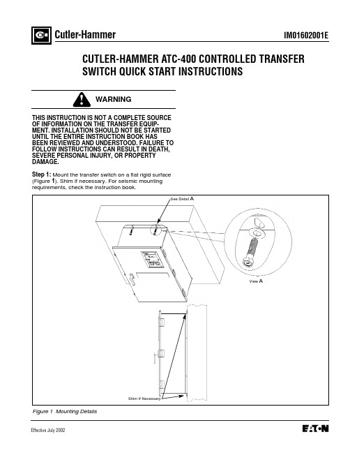
IM01602001EEffective July 2002Cutler-HammerCUTLER-HAMMER ATC-400 CONTROLLED TRANSFER SWITCH QUICK START INSTRUCTIONSTHIS INSTRUCTION IS NOT A COMPLETE SOURCE OF INFORMATION ON THE TRANSFER EQUIP-MENT. INSTALLATION SHOULD NOT BE STARTED UNTIL THE ENTIRE INSTRUCTION BOOK HASBEEN REVIEWED AND UNDERSTOOD. FAILURE TO FOLLOW INSTRUCTIONS CAN RESULT IN DEATH,SEVERE PERSONAL INJURY, OR PROPERTY DAMAGE.Step 1: Mount the transfer switch on a flat rigid surface (Figure 1). Shim if necessary. For seismic mountingrequirements, check the instruction book.Figure 1 Mounting DetailsShim If NecessaryView ASee Detail APage 2Effective 7/02Figure 2 300A, 3 Pole, Automatic Transfer Switch InteriorFuse Disconnect BlockEngine Start ContactsOptional Feature 37Fuse Disconnect BlockSource (S2) Power TerminalsPage 3Effective 7/02Tighten Cables Into TerminalsSee Detail BDetail BTypicalEngine Start Contacts(Red Terminals)Page 4Effective 7/02Figure 6 ATC-400 Logic (Utility Supplying Load)qqThe following lights must be ON:q Source 1 Available q Source 1 ConnectedPerform LED lamp test by depressing and holding. All LED’s should turn on.If not, contact factory for replacement.Page 5Effective 7/02Page 6Figure 7 ATC-400 (Rear View)Effective 7/02Page 7Effective 7/02qqqThe following lights must be ON:q Source 1 Availableq Source 1 Connectedq Source 2 AvailableThe following lights must be ON:q Source 1 Availableq Source 2 Availableq Source 2 ConnectedqqqIM01602001EPage 8Cutler-HammerPittsburgh, Pennsylvania U.S.A.Effective 7/02 (ISI)Style IM01602001E H01Printed in U.S.A.Step 10: ATH4/ATV4 Power Failure Test - Initiate a Load Test by simulating an actual power failure.(1) This should be done by opening the upstream breaker or fused disconnect switch.(2) If the ATS is Service Equipment Rated with no upstream disconnect, use the Normal Control Circuit Disconnect to simulate a power failure (Figure 10).This can be found in one of two places. The first would be located directly beside the normal breaker. The second would be located on the transformer panel/customer connection panel. The normal con- trol circuit disconnect is the disconnect markedNormal.The disconnect switch should be in the ON position for normal operation. Turning the switch to the OFF position will simulate a normal power out- age.Figure 10 Control Disconnect(3) The generator should start and the ATS should transfer to Emergency.(4) After transfer, close the upstream breaker, or close the Normal Control Circuit Disconnect. The TDEN timer should begin counting, and, when com- plete, the ATS should transfer to Normal. The En- gine Cooldown Timer should time out and shut the emergency power unit down.NOTICEWhile performing testing, if an undesired or undoc-umented result occurs, first contact the localGenset dealer. If the result is not corrected, contact the Cutler-Hammer Product Integrity Center at 1-800-210-6208.OFF PositionON Position。
STYLER蒸氣電子衣櫥使用者手冊说明书

使用者手冊STYLER 蒸氣電子衣櫥開始安裝之前,請仔細閱讀這些說明。
這可使安裝簡便,並確保正確安全地安裝產品。
安裝之後,將這些說明放置在產品附近以供將來參考。
繁體中文E523CWMFL71825909 Rev.01_090621 Copyright © 2021 LG Electronics Inc. All Rights Reserved.目錄本手冊所包含的圖片與內容可能與您所購買的機型不同。
本手冊內容以製造商修訂版本爲準。
安全說明使用前請閱讀所有說明 (3)警告聲明 (3)安裝零件和規格 (8)安裝位置要求 (9)打開機器包裝 (12)調平機器 (12)操作操作概述 (17)準備衣物 (17)每次護理之前檢查衣物 (18)放入電器 (20)控制面板 (25)⾏程指南 (27)⾏程選項與額外功能 (32)智慧功能LG ThinQ 應用程式 (33)Smart Diagnosis (35)保養定期清潔 (36)故障排除產品叫修之前 (38)3安全說明繁體中文安全說明使用前請閱讀所有說明下面的安全指導內容旨在預防由於不安全或錯誤產品操作⽽導致的不可預⾒⾵險。
如下所述,指導內容分為「警告」和「注意」兩個部份。
安全訊息警告聲明•爲了減少火災或爆炸、觸電、財產損壞、人員受傷或死亡等⾵險,在使用本電器時,請遵循以下基本安全預防措施:技術安全性•本電器不適合讓⽣理、感觀或⼼智能力不⾜的人員(包括兒童),或者缺乏知識和經驗的人員使用,除非由其監護人監督或指導他們如何使用本電器。
•兒童應當受到監督以確保其不會玩耍本電器。
•請勿在任何情況下切斷或拆下電源線的接地插腳。
為防止個人受傷或電器損壞,電源線必須插入正確接地的插座。
•此電器必須插入受 15 安培保險絲或斷路器保護的 110 VAC 、60-Hz 接地插座。
如果未遵循這些說明,可能導致火災、爆炸或死亡。
•此電器必須插入正確接地的插座。
如果電器未正確接地,可能導致觸電。
WS_繁体中文使用说明书_V1.0

四種單位 N-m, ft-lb, in-lb, kg-cm,可供選擇
5 分鐘進入省電模式 可使用充電電池
1
各部件功能及名稱 30 N-m ~ 135 N-m 系列
操作設定值,然後再回到 0 N-m 。 *5: 環境測試包括:
a. 高溫試驗 b. 低溫試驗 c. 高溫高溼試驗 d.溫度變化試驗 e. 衝擊試驗 f. 振動試驗 g. 落下試驗 *6: 電磁相容性測試包括 : a. 靜電測試(ESD) b.輻射耐受 (RS) c. 輻射量測(RE)
6
使用扳手前注意事項
置入電池 打開電池蓋。 置入兩個 AAA 或是 AA 電池到電池盒中,請
注意正負極方向。 裝上電池蓋,並將電池蓋旋轉至定位。
電池蓋
電池
30 N-m ~ 135 N-m 系列
電池及電池蓋放入方向
200 N-m ~ 340 N-m 系列
注意: 當開啟 30Nm~135Nm 系列扳手的電池蓋時, 將會發現有一個觀測窗,此觀測窗可以觀測 試水貼紙的顏色,以判斷此扳手是否曾經遭 水入侵。
3~60
225
WS3-085 85
3/8 8.5~85 271
WS3-135 135 3/8 6.8~135 380
WS4-135 135 1/2 6.8~135 380
全部型號
精確度*1 操作模式
CN
順時針:±3% 反時針:±4%
峰值保持(P)/追隨(T)
單位選擇
N-m, in-lb, ft-lb,kg-cm
各部件功能及名稱 200 N-m ~ 340 N-m 系列
ST50 Joystick 使用手册说明书

1.LEARN ABOUT THE BASICS…Thank you for purchasing Saitek’s new ST50 Joystick. With its ergonomically-designed pistol grip and sculptured palm rest, this game controller will give you countless hours of exciting, yet comfortable, game play! Moreover, since it was carefully developed to fit a wide variety of hand sizes, it will probably feel like it was made especially for you! TheST50 was designed for IBM PC and compatible systems, and will work with Windows® 95/ 98/Millennium-based games.As shown under Features and Controls, this joystick boasts a thumb-controlled fire button, conveniently located at the top of the grip, plus a fast-reacting and easily-acces-sible finger trigger. You’ll also appreciate the smooth and fluid operation of the built-in throttle. All these features add up to a joystick that’s perfectly suited for many different adventures, including flight simulations, racing games, and so much more!The instructions in this manual were designed to get you started quickly and easily. Once you’ve gone through the initial setup for your new joystick, the games can begin!2.…THEN DO THE CALIBRATION!After setting up the ST50 as described under Getting Connected, you’ll need to cali-brate the unit in Windows® 95/98/Millennium, as described below.a.Click on Start, and select Settings, then Control Panel.b.Double-click the Game Controllers icon. If any previously-loaded controllers appearin the Game Controllers window, they should be removed before you add the ST50 as the active controller. To remove an existing device, highlight the controller byclicking on it, and then click on Remove. Click on Yes to confirm.c.Select Add under the General tab. Select the 3-axis, 2-button joystick option.d.Click on OK, and you’re now back at the main Game Controllers window.e.With the 3-axis, 2-button joystick highlighted, click on the Properties button toopen the Game Controller Properties dialog box.f.Select Calibrate under the Settings tab, and follow the on-screen instructions. Makesure that the Rudder/Pedals box is not selected. Note that the throttle is used tocalibrate the third axis. When the calibration procedure is complete, click on Finish.g.Next, click on the Test tab to check out your calibration. The joystick cursor shouldmove in all directions, and the button indicators should turn on when the button and trigger are pressed. When the throttle is pushed all the way forward and pulled back again, the third axis indicator in the center should go up and down.h.After you’ve finished testing, quit by clicking on OK in the Test window, and OK in theGeneral window. Finally, close the Control Panel window. Now it’s time to load your favorite game and start playing!Note that the actual controls for the thumb button, trigger, and throttle are set within each individual game. Check your game documentation for details.3.HAVE QUESTIONS? HERE’S SOME HELP!a.My computer is not recognizing the ST50 as an active controller. What’swrong?•Check the cable connections. Turn off your computer, and unplug the joystick from the computer’s game port. Then plug it back in, making certain that the connection is snug.•Are you using an extender cable or a Y-connector? Since these cables cansometimes cause problems, we suggest that your ST50 be connected directly tothe game port.•Be sure to remove any existing controllers before you install the ST50, as noted in Section 2.•The game port driver hasn’t been installedproperly.b.The buttons don’t seem to be reacting correctly.Why?•Check your Game Controller Setup, as described in Section 2. Make sure that you have selected the 3-axis, 2-button joystick option.•Try calibrating the unit again. Even if you have already done this, recalibrating can sometimes solve problems.c.The throttle isn’t responding as it should.•Recalibrate the unit, following the directions carefully. Remember that the throttle is used tocalibrate the third axis, and should be pushed all the way forward and backward several times forproper calibration.d.Can I have another controller connected at thesame time?•To avoid potential problems and conflicts, we recommend that you remove any existing controllers before installing the ST50. See Section 2 for details.e.I calibrated the ST50 and loaded my game, but the game instructions say I have to calibrate it again. Why?•Most current games make use of the Windows ® game controller and calibration information. Some games, however, may require you to define the joystick and calibrate it within the program. In these cases, refer to your game manual.4.IF YOU NEED MORE SUPPORT…Give our website a visit at . Besides obtaining help with many of your technical questions, you’ll also find up-to-date news and product information, as well as listings of related links that are sure to interest you. And, while you’re there, why notexplore our website a little further and check out all the other products Saitek has to offer,including a great variety of game controllers, chess computers, and other electronic products—you might just come across something you’ve never seen before!If you need additional help with the setup or use of your ST50 Joystick, you can also obtain comprehensive product support by contacting your nearest Technical Support Center . You’ll find a complete listing of our worldwide affiliates on a separate sheet,included in the box with your ST50. We’ve provided everything you might need, including e-mail addresses, mailing addresses, and telephone numbers. In order to deal with your problems as quickly as possible, we ask that you please follow these guidelines when contacting us:•Have access to your computer when you call! If you are experiencing problems with one particular game, try to have that game loaded.•Provide us with other relevant information, such as your computer’s make and model,details on your hardware and software, the version number of the game, etc.•Describe the problem you are having and the events that led up to it, trying to be as precise as possible. Remember—the better we can understand the problem, the faster we can find the solution!。
M161 型号 401 电动刀具磨刀机产品手册说明书

PRODUCT MANUAL- M161 MODEL 401 NSF ELECTRIC KNIFE SHARPENER-WITH SNAP IN KNIFE GUIDE(for serial #’s higher than 4155 built after may 2002)Please read thoroughly before operation and keep for future referenceModel 401 Knife Sharpener SpecificationsModel No.401Power Requirements115 volt, 1.5 Amps, 50 – 60 HZ230 volt, 0.5 Amps, 50 – 60 HZSpeed1550 RPMSize4” D x 4 ¾” H x 9 ¾” W(102mm x 121mm x 248mm)Weight8.9 lbs. (4.0 kg.)1. Knife Sharpener DescriptionThe Edlund Company Inc manufactures the Model 401 knife sharpener. It is approved by the appropriate certifying organizations. The knife sharpener uses a 3-inch diameter by one-inch wide grinding wheel to sharpen knives and other utensils. The sharpener consists of a grinding wheel, which is mounted on an arbor and attached to a drive motor. The motor is mounted to a stainless steel base using motor mounting plates. The sharpener is enclosed in a stainless steel housing with a plastic knife guide assembly secured to the base with the snap in guides. The unit isequipped with a rocker switch to turn the motor on or off and a safety interlock switch which will not allow the unit to operate if the plastic knife guide is not in place.2. Knife Sharpener OperationTo operate, plug the power cord into a grounded outlet with the same voltage as listed on the bottom of the knife sharpener base. Turn the unit on using the rocker switch and then use the following steps.1. Sanitize your hands and knife prior to sharpening.2. Hold knife against the outside edge of the left slot.Warning! Hold knife firmly so that it will not be pulled away bythe rotation of the grinding wheel.3. Pull the knife through in a horizontal motion keeping pressure onthe wheel light and even.4. Hold the knife against the outside edge of the right slot and pullthrough in a horizontal motion keeping pressure on the wheel lightand even.5. Repeat steps 2-4 until the desired edge is achieved.6. Sanitize knife and hands.Initial sharpening of knives may require several passes to createthe correct angle of the knife. Subsequent sharpening will onlyrequire a few passes to achieve a sharp, long lasting knife-edge.3. Cleaning InstructionsWarnings! Never clean or maintain knife sharpener without unplugging it from the electric source.Never submerge or place knife sharpener in water.Never blow out unit using and air gun- metal may blow inside of the motor and damage it.The knife sharpener must be cleaned after each use.Unplug the unit from the power source and remove theknife guide. To remove the knife guide press the twoplastic tabs (located underneath and towards the frontof the sharpener) towards each other and then lift theblue knife guide upwards (see figure on right). Gentlyshake out the accumulated grinding dust from theinside into a waste receptacle. Wipe the exterior andknife guide using a damp cloth.When the cleaning is complete insert the knife guideinto the knife sharpener cover and make sure that theplastic tabs snap back into place.Trouble Shooting GuideAn Edlund authorized service technician should do all repairs. Call the Factory or Authorized dealer for more information.4. INSTRUCTIONS FOR REPLACING GRIND WHEELThe grinding wheel is designed to last up to several years based on normal use (this may vary depending on use). The grinding wheel is fully worn out and needs replacing when the knife no longer makes contact with the wheel while positioned against the plastic knife guide. Areplacement wheel and arbor can be ordered from your local Edlund dealer as part number#A526S. To replace the grinding wheel, first unplug the unit from the power source. Remove the knife guide. Loosen the setscrew (use a 3/32” Allen wrench) until you are able to slide the wheel and arbor off of the motor shaft (FIGURE 1). Replace with the new wheel and arbor, the factory sets the stone and arbor with Shim (S291). This shim should be placed between the motor andthe wheel. The wheel should be placed flush against the shim and the setscrew tightened. Next remove the shim and the wheel will be set .120 inches away from the motorFIGURE 1. ATTACHING WHEELReplace the knife guide. The grinding wheel should be aligned after installation so that an equal portion of the wheel is visible in the left and right knife guide slots when the knife guide is in place (FIGURE 2). The knife sharpener is now ready for use.FIGURE 2. PROPERLY INSTALLED STONEPart ReferencePARTS LISTPART # QTY DESCRIPTIONA5261ASSEMBLY, #395/401 GRIND WHEELA5361ASSEMBLY, 401 SNAP IN KNIFE GUIDEA5371ASSEMBLY, #401 SNAP IN BASEA5381WELDMENT, #401 SNAP IN COVERB2971BUSHING,1/2"SNAP,3/8"IDC0731CLAMP, #201 CABLEC0921CONNECTOR, #390/395/CH-5000 LEADC0991CORD SET, REGULAR 7', 18/3, GRAYI0041INSULATOR, ECO MICRO SWITCH PADM0141MOTOR, 395/401 115V #7163-7783M0151MOTOR, 395/401 230VN0194NUT, 10-32 PLATED HEXN0201NUT, 10-32 S/S HEXP086F 1PLATE, 401 S/S MOTOR MTG. FRONTP086S 1PLATE, 401 S/S MOTOR MTG. BACKR0231WASHER, #8 S/S LOCKS0494SCREW, 10-32 X 3/8 S/S HEX HEADS0742SCREW, 4-40 X 5/8 BRASS RHMS0853SCREW, 8-32 X 1/4 S/S RHMS4031SWITCH, CH-350 USA LIGHTED ROCKERS4331 1SWITCH, 230VS5611SWITCH, 401 INTERLOCK MICROT0062TERMINAL, #203/266 FEMALE, 3/16T0071TERMINAL, ECO ROUND TONGUET054(3)(4)TERMINAL, 1/4" FEMALE FULLY INSW0108WASHER, #10 S/S FLATW0174WASHER, #10 EXT. TOOTH LOCK, PTDW0192WASHER, #4 INTRL TOOTH LOCK, S/SW0233WASHER, #8 S/S LOCKW1034WASHER, #10 S/S INTERNAL TOOTH LOCKW1051WASHER, 1/4" S/S FLAWarranties:The Edlund Company warrants these products to be free from defects in material and workmanship for a period of one year from date of purchase. The company’s obligation under this warranty is limited to repairing or replacing without charge any parts or parts found to be defective under normal use. It is the responsibility of the purchaser to return the entire unit to the factory or a factory service branch, transportation charges prepaid. This warranty does no cover parts that must be replaced under normal use, including knives and drive gears on can openers. The company authorizes no other warranty, written or verbal. Carrier is responsible for merchandise in transit to you.。
野战918说明书

野战918说明书篇一:BSX5090YZYC野战油库车使用说明书1BSX5090YZYC型野战油库车使用说明书中国人民解放军第三六零三工厂20XX年12月前言BSX5090YZYC型野战油库车配合开设组合式战役野战油库的部队,保障部队战时的用油需要。
该装置实现装卸速度快,操作方便灵活,安全可靠,具有机械化程度高、机动性强等特点。
节省了人力,减轻了工作人员的劳动强度,具有较高的工作效率。
本说明书将详细地向您介绍BSX5090YZYC型野战油库车的主要技术参数、结构形式,使用操作方法及保养规范等,以供用户使用时参考。
除本使用说明书外,野战油库其它重要组件的使用方法及注意事项请参阅相关的使用维护说明书,包括“解放CA1092系列载货汽车驾驶保养手册”和“76-10B型发动机泵使用维护说明书”。
目录1.主要技术参数-------------------------------------------------------12.整车概况-------------------------------------------------------------22.1 整车外形图----------------------------------------------------22.2各部件名称及简介--------------------------------------------3 3.整车基本操作及使用方法--------------------- ------------------43.1方舱装卸主要操作程序------------------------------------- 5 3.2方舱箱体软体油罐主要操作方法------- ------------------6 4.使用注意事项---------------------- -------------------------------75.车辆的维护和保养----------------- ------------------------------86.常见故障与维修--------------------------------------------------1 07.易损件--------------------------------------------------------------118.产品运输及随车文件--------------------------------------------111、主要技术参数2、整车概况 2.1 整车外形图整车外形图见图1篇二:98-10班用棉帐篷使用说明书使泰州98—10班用棉帐篷用说明书二○一六年六月华新特种装备有限公司《98—10班用棉帐篷》使用说明书一、用途:主要供野战条件下寒区部队住宿、办公等使用。
JET 16 x 52 英寸脚剪刀操作说明和零件手册说明书
Operating Instructions and Parts Manual16 x 52 inch Foot ShearModel FS-1652JJET427 New Sanford RoadLaVergne, Tennessee 37086 Part No. M-756202 Ph.: 800-274-6848 Edition 1 10/2015 Copyright © 2015 JET1.0 IMPORTANT SAFETYINSTRUCTIONSREAD ALL INSTRUCTIONS BEFORE USING THIS FOOT SHEAR.WARNING – To reduce the risk of injury:1. Read and understand the entire owner'smanual before attempting assembly or operation.2. Read and understand the warnings posted onthe machine and in this manual. Failure tocomply with all of these warnings may causeserious injury.3. Replace the warning labels if they becomeobscured or removed.4. This foot shear is designed and intended for useby properly trained and experienced personnelonly. If you are not familiar with the proper andsafe operation of a foot shear, do not use untilproper training and knowledge have been obtained.5. Do not use this foot shear for other than itsintended use. If used for other purposes, JETdisclaims any real or implied warranty and holdsitself harmless from any injury that may resultfrom that use.6. Always wear ANSI Z87.1 approved safetyglasses or face shield while using this footshear. (Everyday eyeglasses only have impactresistant lenses; they are not safety glasses.) 7. Before operating the foot shear, remove tie,rings, watches and other jewelry, and rollsleeves up past the elbows. Do not wear looseclothing. Confine long hair. Non-slip footwear oranti-skid floor strips are recommended.8. Wear ear protectors (plugs or muffs) if noisereaches unsafe levels.9. Some dust created by power sanding, sawing,grinding, drilling and other construction activities contain chemicals known to causecancer, birth defects or other reproductive harm. Some examples of these chemicals are:•Lead from lead based paint.•Crystalline silica from bricks, cement and other masonry products.•Arsenic and chromium from chemically treated lumber.Your risk of exposure varies, depending on howoften you do this type of work. To reduce yourexposure to these chemicals, work in a well-ventilated area and work with approved safetyequipment, such as face or dust masks that arespecifically designed to filter out microscopicparticles.10. Do not operate this machine while tired or underthe influence of drugs, alcohol or any medication.11. Keep safety guards in place at all times whenthe machine is in use. If removed for maintenance purposes, use extreme caution and replace the guards immediately after completion of maintenance.12. Check damaged parts. Before further use of themachine, a guard or other part that is damagedshould be carefully checked to determine that itwill operate properly and perform its intendedfunction. Check for alignment of moving parts,binding of moving parts, breakage of parts, mounting and any other conditions that mayaffect its operation. A guard or other part that isdamaged should be properly repaired or replaced.13. Provide for adequate space surrounding workarea and non-glare, overhead lighting.14. Keep the floor around the machine clean andfree of scrap material, oil and grease.15. Keep visitors a safe distance from the workarea. Keep children away.16. Make your workshop child proof with padlocks,master switches or by removing starter keys. 17. Give your work undivided attention. Lookingaround, carrying on a conversation and “horse-play” are careless acts that can result in seriousinjury.18. Maintain a balanced stance at all times so thatyou do not fall into the blade or other movingparts. Do not overreach or use excessive forceto perform any machine operation.19. Use recommended accessories; improperaccessories may be hazardous.20. Maintain tools with care. Keep blades sharp andclean for the best and safest performance.Follow instructions for lubricating and changingaccessories.21. Do not stand on the machine. Serious injurycould occur if the machine tips over.22. Remove loose items and unnecessary workpieces from the area before operating the machine.23. Keep hold-down clearance to table as small aspossible while allowing just enough room tofeed stock.3 24. Do not cut rods with the foot shear.25. Sheet metal stock has sharp edges; use cautionwhen handling to prevent cuts. 26. Keep hands and fingers clear of the blade andhold-down area. Do not place hands or fingers between material and table when operating. 27. Do not exceed rated capacity of the foot shear. 28. Do not exceed front gauge capacity – materialmust not be so long that it interferes in any way with safe operation of the foot pedal.Familiarize yourself with the following safety notices used in this manual:This means that if precautions are not heeded, it may result in minor injury and/or possiblemachine damage.This means that if precautions are not heeded, it may result in serious, or possibly even fatal,injury.SAVE THESE INSTRUCTIONS2.0 About this manualThis manual is provided by JET, covering the safe operation and maintenance procedures for a JET Model FS-1652T Foot Shear. This manual contains instructions on installation, safety precautions, general operating procedures, maintenance instructions and parts breakdown. Your machine has been designed and constructed to provide consistent, long-term operation if used in accordance with the instructions as set forth in this document. If there are questions or comments, please contact your local supplier or JET. JET can also be reached at our web site: .Retain this manual for future reference. If the machine transfers ownership, the manual should accompany it.Read and understand the entire contents of this manual before attempting assembly oroperation! Failure to comply may cause serious injury!3.0 Table of contentsSection Page1.0 IMPORTANT SAFETY INSTRUCTIONS (2)2.0 About this manual (3)3.0 Table of contents (4)4.0 Specifications (5)5.0 Setup and assembly (6)5.1 Shipping contents (6)5.2 Tools required for assembly (6)5.3 Unpacking and cleanup (6)5.4 Extension arms and front stop (6)5.5 Back stop (6)6.0 Adjustments (7)6.1 Back stop adjustment (7)6.2 Table/side panel adjustment (7)6.3 Blade clearance adjustment (7)7.0 Operation (7)8.0 User-maintenance (8)8.1 Spring tension (8)8.2 Gib adjustment (8)8.3 Blade care (8)9.0 Troubleshooting FS-1652T Foot Shear (8)10.0 Replacement Parts (8)10.1.1 Exploded View: FS-1652J Foot Shear (9)10.1.2 Parts List: FS-1652J Foot Shear (10)11.0 Warranty and service (12)4.0 SpecificationsModel number ......................................................................................................................................... FS-1652T Stock number . (756202)Capacities:Mild steel ............................................................................................................................................... 16 gauge Maximum shearing length .......................................................................................................... 52 in. (1321mm) Back gauge capacity .................................................................................................................... 28 in. (710mm) Front gauge capacity ................................................................................................................... 22 in. (550mm) Blade features:Lower blade ........................................................................................ 2 cutting edges with 2-degree edge relief Upper blade ...................................................................................... 4 cutting edges with 2-degree edge reliefs Primary materials:Frame .................................................................................................................................................... cast iron Table ............................................................................................................................ cast iron, ground surface Lower blade .............................................................................................. hardened stainless steel, 48~58HRC Upper blade .............................................................................................. hardened stainless steel, 48~58HRC Hold-down .............................................................................................................................................. cast iron Dimensions:Overall dimensions, fully assembled (LxWxH) ................................... 63 x 74 x 42 in. (1600 x 1880 x 1067mm) Footprint (LxW) ................................................................................................ 62-1/4 x 72 in. (1580 x 1830mm) Shipping dimensions (LxWxH) .............................................................. 66 x 30 x 45 in. (1680 x 760 x 1150mm) Weights:Net weight ................................................................................................................................ 1100 lbs (499 kg) Shipping weight ....................................................................................................................... 1220 lbs (554 kg) The specifications in this manual were current at time of publication, but because of our policy of continuous improvement, JET reserves the right to change specifications at any time and without prior notice, without incurring obligations.5.0 Setup and assemblyRead and understand all assembly instructions before attempting assembly. Failure to comply may cause serious injury.5.1 Shipping contentsSee Figures 1 and 2.1 Foot shear2 Adjustment blocks – A1 Bevel gauge – B2 Extension arms – C2 Back stop rods – D1 Back stop – E1 Front stop – F3 Wing nuts – G4 Cotter pins – H4 Hex cap bolts, M12x45 – I4 Flat washers, wide, M12 – J2 Hex cap bolts, M10x20 – K2 Flat washers, M10 – L2 Long clevis pins – M4 Short clevis pins – N3 T-nuts – O3 Flat Washers, M12 – PFigure 1Figure 25.2 Tools required for assembly16mm and 19mm wrenches5.3 Unpacking and cleanup1. Remove crating from around machine. Inspectcontents for shipping damage. Report damage,or any missing parts, to your distributor. Do notdiscard packing material until shear is assembled and operating satisfactorily.2. Remove bolts holding machine to pallet. Usehoist, forklift, or similar means to lift shear offpallet and move to desired location.3. Carefully move machine to a level foundation.Machine location must allow access to all sides.Secure shear to floor using lag screws (notprovided) or other appropriate fasteners.4. Remove any protective straps from aroundmachine, and carefully clean all rust protectedsurfaces with a mild solvent or kerosene and asoft rag. Do not use lacquer thinner, paint thinner, or gasoline, as these will damage painted surfaces. Use caution when cleaningaround blade area.5. Coat all machined surfaces with a light coat ofoil to inhibit rust. Paste wax may be used on theexposed table surface.Assembly Note: Prior to shipment the foot shear is adjusted by the manufacturer for proper operation. If the machine does not operate properly, or the stand does not sit squarely on the floor, refer to sect.6.2, Table/side panel adjustment.5.4 Extension arms and front stop1. Install four hex cap bolts and washers (I/J,Figure 3) loosely into front table edge.2. Slide extension arm (C) onto bolts, leavingextension arm slightly above table surface.Make bolts snug, and tap down extension armuntil level with table surface. Tighten bolts firmly. Repeat for other extension arm.Figure 33. Install T-nuts, flat washers and wing nuts(O,P,G) to bevel gauge (B) and front stop (F),and slide them into the channels.5.5 Back stop1. Insert rod (D, Figure 4) through adjustmentblock (A) and into frame. Make sure both rodsare inserted an even amount into the frame.Tighten securely in place with screw (D1).2. Attach back stop (E) to adjustment block flangewith M10 screw and flat washer (K,L) from underneath.Figure 46.0 Adjustments6.1 Back stop adjustment1. To position back stops, loosen all knobs (A1,A2,Figure 4) and slide adjustment blocks close to desired position on scale.2. Tighten knob (A1) and rotate dial (A3) to adjustto final position.3. Tighten remaining knobs (A2).6.2 Table/side panel adjustmentIf floor is level but shear does not sit evenly, adjust as follows:1. Loosen two bolts (R, Figure 5) on each side ofshear.2. Loosen hex nuts and bolts (S, Figure 5). Tablemust rest squarely on right and left side panels at all four corners while screws are loose. Shim legs at floor if necessary.3. Securely tighten bolts and hex nuts (R,S) whenadjustments are complete.Figure 5 6.3 Blade clearance adjustmentBlade clearance has been adjusted by the manufacturer for the gauge capacity of the shear. If the shear does not cut properly during operations, identify the specific problem: Place heavy sheet of paper (such as brown craft paper approximately 0.005 in. thick) in cutting position, along entire length of table. Slowly press foot lever.If shear does not cut paper: Move lower blade toward upper blade. Slightly loosen bolts (R, Figure 5) and loosen hex nuts and turn bolts (S, Figure 5) to move lower blade toward upper blade. Distance between upper and lower blades should be 0.002 to 0.005 inches. Do NOT let blades overlap.Repeat test cut of paper. When satisfied, tighten hex nuts (S, Figure 5) and bolts (R, Figure 5).If shear cuts paper on the ends, but not the center: Loosen hex nut and turn tie-rod adjusting screw (Figure 6) clockwise, as viewed from back, until paper is cut the entire length. Retighten hex nut against frame.If shear cuts paper in the center, but not the ends: Loosen hex nut and turn tie-rod adjusting screw (Figure 6), counter-clockwise until paper is cut the entire length. Retighten hex nut against frame.Figure 6Make sure scales on table top are square to blade, and also show correct distance from blade. Make test cuts to verify that scales are correct. If adjustment is needed, loosen bolts and shift scales as needed. Retighten bolts before operating.7.0 Operation1. Slide material beneath hold-down and againstback stop and side stops or bevel gauge.Do not place hands between material and table while operatingshear.2. Press foot lever all the way down until cuttingaction is complete.3. Release foot lever, which will rise to originalposition.8.0 User-maintenanceLubricate all pivot points on machine daily. Periodically apply light coat of paste wax, or other commercial protectant, to table surface.Additional clevis and cotter pins are provided with the foot shear, should installed ones need replacing due to wear or shearing.8.1 Spring tensionThe Foot lever spring return can be adjusted by tightening hex nuts (#47, exploded view).The spring return can be adjusted on the hold-down by turning hex nuts (#10, exploded view).8.2 Gib adjustmentThree gib screws (#32, exploded view) can be adjusted for play in each shim. Adjust for smooth travel.8.3 Blade careUse thick gloves whenhandling shear blades.Wipe blade lightly with oil after use.Upper blade is 4-way, and can be removed and flipped for a sharp edge three times before requiring sharpening.Bottom blade is 2-way and can be flipped once for a sharp edge before requiring sharpening.9.0 Troubleshooting FS-1652T Foot ShearSymptom Possible Cause Correction Burrs on sheared edge.Low quality materials. Use better grade steel. Dull blade(s).Turn or sharpen blade(s).Incorrect blade clearance, excessive gap between blades. Adjust blades closer.Gibs out of adjustment. Tighten gibs.Won’t cut material, orcuts with difficulty.Material exceeds machine capacity. Use proper gauge material. Dull blade(s).Turn or sharpen blade(s).Incorrect blade clearance, excessive gap between blades.Adjust blades closer. Stock shifts while cutting.Insufficient hold-down pressure. Increase spring pressure of hold-down. Dull blade(s).Turn or sharpen blade(s).Lower blade not even with table surface. Adjust blade; use shims if blade has been reground. Cuts not square.Insufficient hold-down pressure. Increase spring pressure of hold-down. Unequal blade gap across length of blade.Adjust for equal blade gap. Uneven contact with guides. Place material evenly against guides. Blade is bowed.Replace blade.10.0 Replacement PartsReplacement parts are listed on the following pages. To order parts or reach our service department, call 1-800-274-6848 Monday through Friday, 8:00 a.m. to 5:00 p.m. CST. Having the Model Number and Serial Number of your machine available when you call will allow us to serve you quickly and accurately.10.1.1 Exploded View: FS-1652J Foot Shear10.1.2 Parts List: FS-1652J Foot ShearIndex No Part No Description Size Qty1 ................ FS1652J-01............... Table ................................................................... . (1)2 ................ FS1652J-02............... Cutter Bar ........................................................... . (1)3 ................ FS1652J-03............... Hold Down .......................................................... . (1)4 ................ FS1652J-04............... R.H. Side Panel .................................................. . (1)5 ................ FS1652J-05............... L.H. Side Panel ................................................... . (1)6 ................ FS1652J-06............... Front Extension Arm ........................................... . (2)7 ................ F009545 .................... Hex Cap Bolt....................................................... M12-1.75x45 . (4)8 ................ FS1652J-08............... Spring ................................................................. . (2)9 ................ FS1652J-09............... Stud .................................................................... . (2)10 .............. F004545 .................... Cap Nut............................................................... M12-1.75 . (2)11 .............. F009558 .................... Hex Cap Bolt....................................................... M12-1.75x80 . (2)12 .............. F002646 .................... Flat Washer ........................................................ ø12xØ24x2.5 mm .. (6)13 .............. FS1652J-13............... Finger Guard....................................................... . (1)14 .............. F001203 .................... Pan Head Machine Screw .................................. M6-1.0x16 .. (5)16 .............. FS1652J-16............... Table Scale ........................................................ . (2)17 .............. F008791 .................... Hex Cap Bolt....................................................... M8-1.25x25 (4)18 .............. F009511 .................... Hex Cap Bolt....................................................... M10-1.5x60 (2)19 .............. F009510 .................... Hex Cap Bolt....................................................... M10-1.5x55 (2)20 .............. F002643 .................... Flat Washer ........................................................ ø10xØ20x2 mm (24)21 .............. FS1652J-21............... Bolt...................................................................... M16x120 . (4)22 .............. F002650 .................... Washer ............................................................... ø16xØ30x3 mm .. (4)23 .............. F003088 .................... Hex Nut ............................................................... M16-2.0 (4)24 .............. FS1652J-24............... Upper Knife ......................................................... . (1)25 .............. FS1652J-25............... Lower Knife ......................................................... . (1)26 .............. F005432 .................... Socket Head Cap Screw..................................... M10-1.5x45 (8)27 .............. F005433 .................... Socket Head Cap Screw..................................... M10-1.5x50 (8)28 .............. F002643 .................... Flat Washer ........................................................ ø10xØ20x2 mm .. (8)29 .............. F002643 .................... Flat Washer ........................................................ ø10xØ20x2 mm .. (8)30 .............. FS1652J-30............... Hex Cap Screw (Copper).................................... M10x50 (2)31 .............. FS1652J-31............... Gib ...................................................................... . (2)32 .............. F009511 .................... Hex Cap Bolt....................................................... M10-1.5x60 (6)33 .............. F003080 .................... Hex Nut ............................................................... M10-1.5 . (12)34 .............. FS1652J-34............... Rod ..................................................................... . (1)35 .............. FS1652J-35............... Washer ............................................................... 14 mm .. (2)36 .............. F003087 .................... Hex Nut ............................................................... M14-2.0 (2)37 .............. FS1652J-37............... Special Screw ..................................................... M16-2.0x60 (1)38 .............. F003084 .................... Hex Nut ............................................................... M12-1.75 . (2)39 .............. F002650 .................... Flat Washer ........................................................ ø16xØ30x3 mm .. (5)40 .............. F009503 .................... Hex Cap Bolt....................................................... M10-1.5x40 (2)41 .............. FS1652J-41............... Spring ................................................................. . (2)42 .............. FS1652J-42............... Spring Cap .......................................................... . (4)43 .............. FS1652J-43............... Swivel Top .......................................................... . (2)44 .............. FS1652J-44............... Swivel Bottom ..................................................... . (2)45 .............. FS1652J-45............... Stud .................................................................... . (2)46 .............. F002650 .................... Flat Washer ........................................................ ø16xØ30x3 mm .. (2)47 .............. F003126 .................... Hex Nut ............................................................... M16-2.0 (2)48 .............. FS1652J-48............... Bracket................................................................ . (2)49 .............. F008836 .................... Hex Cap Bolt....................................................... M10-1.5x25 (6)50 .............. F003091 .................... Hex Nut ............................................................... M20-2.5 (4)51 .............. FS1652J-51............... Pin....................................................................... Ø12x85 mm .. (4)52 .............. FS1652J-52............... Clevis Pin ............................................................ Ø12x45 mm .. (6)53 .............. FS1652J-53............... Brake Pin ............................................................ . (2)54 .............. FS1652J-54............... Pedal Assembly .................................................. . (1)55 .............. FS1652J-55............... Connection Bar ................................................... . (1)56 .............. FS1652J-56............... Clevis Pin ............................................................ Ø20x35 mm .. (3)57 .............. F009542 .................... Hex Cap Bolt....................................................... M12-1.75x25 . (4)58 .............. F008836 .................... Hex Cap Bolt....................................................... M10-1.5x25 (2)59 .............. FS1652J-59............... Back Stop ........................................................... . (1)60 .............. FS1652J-60............... Extension Bar ..................................................... . (2)61 .............. FS1652J-61............... Adjusting Block ................................................... . (1)Index No Part No Description Size Qty62 .............. FS1652J-62............... Adjusting Dial ...................................................... . (2)63 .............. FS1652J-63............... Adjusting Screw .................................................. . (2)64 .............. F009498 .................... Hex Cap Bolt....................................................... M10-1.5x30 (4)65 .............. FS1652J-65............... Knob ................................................................... . (4)66 .............. FS1652J-66............... Adjusting Bracket ................................................ . (2)67 .............. FS1652J-67............... Plate.................................................................... . (2)68 .............. F008832 .................... Hex Cap Bolt....................................................... M10-1.5x20 (4).................. FS1652J-80............... Back Stop Rod Assembly (#69, #78, #79) .......... . (2)69 .............. FS1652J-69............... Back Stop Rod ................................................... . (2)70 .............. F003088 .................... Hex Nut ............................................................... M16-2.0 (1)71 .............. FS1652J-71............... Front Stop ........................................................... . (1)72 .............. F002646 .................... Flat Washer ........................................................ ø12xØ24x2.5 mm .. (9)73 .............. FS1652J-73............... “T” Bolt ................................................................ M12 (3)74 .............. F012160 .................... Wing Nut ............................................................. M12-1.75 . (3)75 .............. FS1652J-75............... Angle Gauge ....................................................... . (1)76 .............. F003835 .................... Cotter Pin ............................................................ Ø3.2x45 mm .. (10)77 .............. F002636 .................... Flat Washer ........................................................ ø6xØ12x1.6 mm . (5)78 .............. FS1652J-78............... Scale ................................................................... . (2)79 .............. FS1652J-79............... Rivet.................................................................... 2x5 mm (4).................. LM000077 ................. ID Label, FS-1652J (not shown) ......................... . (1).................. LM000135 ................. Label – Gauge Capacities (not shown)............... . (1).................. LM000134 ................. Warning Label (not shown) ................................. . (1).................. JET-165..................... JET Logo with adhesive (not shown) .................. 165x68mm . (1)Some parts are shown for reference only, and may not be available individually.Non-proprietary parts, such as fasteners, can usually be found at local hardware stores, or may be ordered from JET.。
inspire user manual zh-cn说明书
用户手册版本 2.1目录开始 (5)包装盒内容 (5)设置 Inspire (6)为智能设备充电 (6)使用手机或平板电脑进行设置 (7)使用 Windows 10 电脑进行设置 (7)在 Fitbit 应用程序上查看您的数据 (8)佩戴 Inspire (9)请将 Inspire 佩戴在您的手腕上 (9)固定腕带 (9)用手习惯 (10)将 Inspire 置于配夹中 (10)佩戴配夹 (11)更换表带 (12)移除腕带 (12)安装腕带 (12)基础信息 (13)导航 Inspire (13)基本浏览指南 (13)快速设置 (15)保养Inspire (15)更改钟面 (16)通知 (17)设置通知 (17)查看收到的通知 (17)关闭通知 (18)计时功能 (19)设置闹钟 (19)关闭或延后闹钟 (20)使用计时器应用程序 (20)活动和睡眠情况 (21)追踪每日活动目标 (22)选择目标 (22)追踪每小时的活动 (22)自动追踪您的锻炼 (22)追踪您的睡眠 (23)设定睡眠目标 (23)了解您的睡眠习惯 (23)更新、重启和清除 (24)更新 Inspire (24)重启 Inspire (24)清除 Inspire (24)故障排除 (25)设备无响应 (25)一般信息和规格 (26)传感器 (26)材料 (26)无线技术 (26)触觉反馈 (26)电池 (26)内存 (26)显示屏 (26)腕带尺寸 (26)环境条件 (27)了解更多 (27)退货政策和保修 (27)法规及安全注意事项 (28)美国:联邦通讯协会 (FCC) 声明 (28)加拿大:加拿大工业部 (IC) 声明 (29)欧盟 (EU) (30)阿根廷 (31)澳大利亚和新西兰 (31)中国 (31)以色列 (33)日本 (33)墨西哥 (33)摩洛哥 (33)尼日利亚 (34)阿曼 (34)巴基斯坦 (34)菲律宾 (35)塞尔维亚 (35)韩国朝鲜 (35)台湾 (36)阿联酋 (37)赞比亚 (38)安全声明 (38)开始Fitbit Inspire 是一款非常友好的健康运动手环,可每天帮助您建立健康的生活习惯。
RAZER BLADE 15 使用者手冊说明书
主指南目錄1. 內含 (2)2. 註冊即可獲得保固 (3)3. 設定你的筆記型電腦 (4)4. 供下載安裝驅動程式 (5)5.使用你的 RAZER BLADE 15 (6)6.設定你的 RAZER BLADE 15 (7)7.安全與維護 (21)8.法律條文 (23)內含▪型號:陣列麥克風紅外線感測模組內建網路攝影機網路攝影機指示燈吋螢幕立體聲揚聲器光學按鍵軸光學按鍵軸具有™功能各鍵獨立的全鍵無衝突鍵盤電源鍵多點觸控軌跡板前置電源指示燈電源埠連接埠連接埠音訊麥克風耳機混合接孔™連接埠連接埠防盜鎖孔▪電源變壓器適用當地插座的電源線▪微纖維清潔布▪重要產品資訊指南註冊即可獲得保固你不僅擁有一台超棒的筆電,更享有年有限原廠保固服務和年有限電池保固。
前往註冊,即可讓你的筆電發揮所有潛力並享受獨家好康產品序號標示於此處。
保固可能因區域而有所不同,且會根據適用的當地法規而異。
有問題嗎?歡迎來信詢問支援小組:設定你的筆記型電腦將適當的電源線連接到電源變壓器,將電源變壓器的插頭插入電源插座,接著將電源線接到上的電源插孔。
請使用你所在區域適用的電源線。
第一次使用你的筆電時,請將電腦完全充飽電,或在開機前連接至電源插座。
將完全充飽電需要至少個小時。
開啟電源。
電源指示燈會顯示筆電的狀態。
請依照畫面上的說明來完成設定步驟。
當系統出現提示時,建議你將筆電連線到具網際網路連線的無線網路。
睡眠模式已開機低電量警告(剩電力)低電量警告(剩電力)電源指示燈AC 電源線電源變壓器供下載安裝驅動程式你不但可以透過下載和其他所支援週邊設備的驅動程式或韌體更新,還可以透過自訂你所有裝置的進階設定和燈光效果。
登入後,會自動將這些個人化設定儲存到雲端,如此一來你就可以在任何一部電腦存取這些設定。
請確定你的筆電具備可使用的網際網路連線。
根據預設,一旦你登入,即會自動開啟。
只要註冊,或以現有帳號登入。
你也可以以訪客身分繼續使用,但是你將無法將你的任何設定儲存到雲端。
Razer Blade Stealth 用户手册说明书
User ManualRZ09-0281/RZ09-028 .PACKAGE CONTENTS▪Razer Blade Stealth▪USB-C power adapter▪Micro-fiber cleaning cloth▪Important Product Information GuideDEVICE LAYOUTA.Array microphoneB.Infrared sensorC.Built-in webcamD.Webcam indicator lightE.13.3” DisplayF.Stereo speakers incorporating Dolby Atmos®G.Backlit keyboardH.Power keyI.Multi-touch trackpadJ.Front LED power indicatorK.Power port / Thunderbolt™ 3 port (USB-C™) B 3.1 portsM.3.5 mm combo portN.Power port / USB-C™ portSETTING UP YOUR RAZER BLADE STEALTHCONNECT THE POWER ADAPTER AS FOLLOWS:Make sure that the AC plug is properly inserted into the power outlet and the power adapter. Insert the power adapter’s USB-C connector into any of the Razer Blade Stealth’s power ports. Press the power key to turn on your Razer Blade Stealth.*Use the appropriate power cord for your region.For first time use, please fully charge your RazerBlade Stealth or connect it to a power outlet beforeturning it on. It takes at least 2 hours to fully chargethe Razer Blade Stealth.CONNECTING TO THE INTERNETDisclaimer: The screens shown are subject to change based on the current version of your Operating System.1. Click the wireless network icon () to bring up the Wireless network list. Thesystem will automatically search for wireless networks in range.2. Click the network you wish to connect to and click Connect.3. Enter the network password (if any) and select whether to enable network sharing.Click Next.4. Once you are connected to the wireless network, click anywhere outside thewindow to return to the desktop.RAZER SYNAPSE 3 ACCOUNT CREATION & INSTALLATIONRazer Synapse 3 allows your Razer Blade Stealth and other supported Razer peripherals to download drivers and firmware updates. Razer Synapse 3 also enables your custom settings to be stored on cloud servers so that they can be accessed anytime, anywhere.1. Razer Synapse 3 will start automatically once you enter Windows 10.2. Register for a Razer Synapse 3 account and confirm your new account.3. Open Razer Synapse 3 and login to your account.4. Wait until Razer Synapse 3 automatically downloads and installs the necessarydrivers.USING YOUR RAZER BLADE STEALTHSTATUS INDICATORKEYBOARD FEATURESPressing the “FN” key in combination with the function keys will activate their secondary functions. Function keysSecondary function descriptionThe audio volume controls allow you to mute ( ), decrease ()and increase () the audio output.Toggles the monitor output.The media keys allow you to play/pause () the current track, returnto the previous track () or skip to the next track ().The screen brightness keys allow you to decrease () or increase() the brightness of the Razer Blade Stealth’s screen.SleepOnLow battery (10% left)Low battery (3% left)Front LED indicator() the brightness of your keyboard’s LEDs. CONFIGURING YOUR RAZER BLADE STEALTHNote: The features listed here require you to log in to Razer Synapse. These features arealso subject to change based on the current software version and your Operating System.The Lighting Tab on Razer Synapse 3 gives you the flexibility to customize your Razer Blade Stealth through different quick effects or you can create your own using the Chroma Studio. If you have other supported Razer Chroma-enabled devices, you can synchronize their lighting effects with your Razer Blade Stealth. NameDescription How to set up BreathingThe keyboard fades in and out of the selected color(s)Select up to 2 colors or randomize colors Spectrum cyclingThe lighting will cycle between 16.8million colors indefinitelyNo further customization is requiredStaticThe LEDs will remain lit in theselected color Select a colorREGISTRATION / TECHNICAL SUPPORTREGISTRATIONRegister your product online at /warranty using your Razer ID to get real-time information on your product’s warranty status.If you haven’t registered for a Razer ID yet, register now at to get a wide range of Razer benefits.Your product’s serial number canbe found here.TECHNICAL SUPPORT▪ 1 year limited manufacturer’s warranty.▪ 1 year limited battery warranty.▪Access to manual and free online technical support at Please refer to the Online Master Guide at for in-depth instructions on how to configure and use your Razer Blade Stealth.SAFETY AND MAINTENANCESAFETY GUIDELINESIn order to achieve maximum safety while using your Razer Blade Stealth, we suggest that you adopt the following guidelines:1. Should you have trouble operating the device properly and troubleshooting does notwork, unplug the device and contact the Razer hotline or go to for assistance.2. Do not take apart the device (doing so may void your warranty) and do not attemptto operate it under abnormal current loads.3. Keep the device away from liquid, humidity or moisture. Operate the device onlywithin the specific temperature range of 0°C (32°F) to 40°C (104°F). Should thetemperature exceed this range, unplug and/or switch off the device in order to letthe temperature stabilize to an optimal level.COMFORTResearch has shown that long periods of repetitive motion, improper positioning of your computer peripherals, incorrect body position, and poor habits may be associated with physical discomfort and injury to nerves, tendons, and muscles. Below are some guidelines to avoid injury and ensure optimum comfort while using your Razer Blade Stealth.1. Position your laptop directly in front of you. If you have an external mouse, positionit next to the laptop. Place your elbows next to your side, not too far away and your mouse within easy reach.2. Adjust the height of your chair and table so that the laptop is at or below elbowheight.3. Keep your feet well supported, posture straight and your shoulders relaxed.4. During gameplay, relax your wrist and keep it straight. If you do the same tasks withyour hands repeatedly, try not to bend, extend or twist your hands for long periods.5. Do not rest your wrists on hard surfaces for long periods. When using an externalmouse, use a wrist rest to support your wrist while gaming.6. Do not sit in the same position all day. Get up, step away from your desk and doexercises to stretch your arms, shoulders, neck and legs.7. If you should experience any physical discomfort while using your laptop, such aspain, numbness, or tingling in your hands, wrists, elbows, shoulders, neck or back, please consult a qualified medical doctor immediately.BATTERY WARNINGThe Razer Blade Stealth contains an internal, lithium-ion rechargeable battery. In general, the life expectancy of such battery is dependent upon usage. If you suspect that the lithium-ion rechargeable battery inside the Razer Blade Stealth may be drained (has a low charge), try charging it. If the battery does not recharge after several attempts, it may be non-operational.Do not open, mutilate, or expose to conducting materials (metal), moisture, liquid, fire, or heat. Doing so may cause the battery to leak or explode, resulting in personal injury. Donot use or charge the battery if leaking, discolored, or deformed. Do not leave the rechargeable battery discharged or unused for extended periods. When not using your Razer Blade Stealth battery for more than 30 days, be sure to store the battery in a fully charged state. Do not tamper with the battery. Dispose of the used battery according to local regulations.LEGALESECOPYRIGHT AND INTELLECTUAL PROPERTY INFORMATION©2018 Razer Inc. All rights reserved. Razer, the triple-headed snake logo, Razer logo, “For Gamers. By Gamers.”, and “Powered by Razer Chroma” logo are trademarks or registered trademarks of Razer Inc. and/or affiliated companies in the United States or other countries.Windows and the Windows logo are trademarks of the Microsoft group of companies.Manufactured under license from Dolby Laboratories. Dolby, Dolby Atmos, and the double-D symbol are trademarks of Dolby Laboratories.Thunderbolt and the Thunderbolt logo are trademarks of Intel Corporation in the U.S.and/or other countries.The terms HDMI and HDMI High-Definition Multimedia Interface, and the HDMI Logo are trademarks or registered trademarks of HDMI Licensing LLC in the United States and other countries.Razer Inc. (“Razer”) may have copyright, trademarks, trade secrets, patents, patent applications, or other intellectual property rights (whether registered or unregistered) concerning the product in this guide. Furnishing of this guide does not give you a license to any such copyright, trademark, patent or other intellectual property right. The Razer Blade Stealth (the “Product”) may differ from pictures whether on packaging or otherwise. Razer assumes no responsibility for such differences or for any errors that may appear. Information contained herein is subject to change without notice.LIMITED PRODUCT WARRANTYFor the latest and current terms of the Limited Product Warranty, please visit/warranty.LIMITATION OF LIABILITYRazer shall in no event be liable for any lost profits, loss of information or data, special, incidental, indirect, punitive or consequential or incidental damages, arising in any way out of distribution of, sale of, resale of, use of, or inability to use the Product. In no event shall Razer’s liability exceed the retail purchase price of the Product.GENERALThese terms shall be governed by and construed under the laws of the jurisdiction in which the Product was purchased. If any term herein is held to be invalid or unenforceable, then such term (in so far as it is invalid or unenforceable) shall be given no effect and deemed to be excluded without invalidating any of the remaining terms. Razer reserves the right to amend any term at any time without notice.FCC DECLARATION OF CONFORMANCEThis equipment has been tested and found to comply with the limits for a Class B digital device, pursuant to part 15 of the FCC Rules. These limits are designed to provide reasonable protection against harmful interference in a residential installation. This equipment generates, uses and can radiate radio frequency energy and, if not installed and used in accordance with the instructions, may cause harmful interference to radio communications. However, there is no guarantee that interference will not occur in a particular installation. If this equipment does cause harmful interference to radio or television reception, which can be determined by turning the equipment off and on, the user is encouraged to try to correct the interference by one or more of the following measures:▪Reorient or relocate the receiving antenna.▪Increase the separation between the equipment and the receiver.▪Connect the equipment into an outlet on a circuit different from that to which the receiver is connected.▪Consult the dealer or an experienced radio TV technician for help.For more information, refer to the online help system on .FCC CAUTION STATEMENTAny changes or modifications not expressly approved by the party responsible for compliance could void the user's authority to operate this equipment.This device complies with Part 15 of the FCC Rules. Operation is subject to the following two conditions:▪This device may not cause harmful interference, and▪This device must accept any interference received, including interference that may cause undesired operation.Responsible party: Razer Inc.Address: 201 3rd Street, Suite 900, San Francisco,CA 94103,USAIMPORTANT NOTE:FCC Radiation Exposure Statement:This equipment complies with FCC radiation exposure limits set forth for an uncontrolled environment. End users must follow the specific operating instructions for satisfying RF exposure compliance. This transmitter must not be co-located or operating in conjunction with any other antenna or transmitter.USAGE RESTRICTIONSThis Razer device was developed and designed to comply with the various wireless and telecom agency requirements throughout the world. This ensures that the device do not cause any harm to Public Switching Telecommunication Networks (PSTN) and do not violate any power and frequency spectrum allocations on a country by country basis. This device was also designed to be compliant with regulatory agency limits for Electromagnetic Compatibility (EMC).IMPORTANT NOTICE FOR USE IN HEALTHCARE ENVIRONMENTSThis Razer device is not a medical device and is not listed under UL or IEC 60601 (or equivalent). This device should be kept at a certain distance to avoid harmful effects to patients or medical equipment.AVIATION USAGE RESTRICTIONSCertain restrictions apply to this device while on-board an aircraft. Razer encourages you to understand these restrictions to ensure the flight’s safety and security.Canada StatementThis device complies with Industry Canada’s licence-exempt RSSs. Operation is subject to the following two conditions:(1) This device may not cause interference; and(2) This device must accept any interference, including interference that may cause undesired operation of the device.Le présent appareil est conforme aux CNR d’Industrie Canada applicables aux appareils radio exempts de licence. L’exploitation est autorisée aux deux conditions suivantes :(1) l’appareil ne doit pas produire de brouillage;(2) l’utilisateur de l’appareil doit accepter tout brouillage radioélectrique subi, même si le brouillage est susceptible d’en compromettre le fonctionnement.This transmitter must not be co-located or operating in conjunction with any other antenna or transmitter. This equipment should be installed and operated with a minimum distance of 0 mm between the radiator and your body.Cet émetteur ne doit pas être Co-placé ou ne fonctionnant en même temps qu'aucune autre antenne ou émetteur. Cet équipement devrait être installé et actionné avec une distance minimum de 0 mm entre le radiateur et votre corps."The device for operation in the band 5150-5250 MHz is only for indoor use to reduce the potential for harmful interference to co-channel mobile satellite systemsles dispositifs fonctionnant dans la bande 5150-5250 MHz sont réservés uniquement pour une utilisation à l’intérieur afin de réduire les risques de brouillage préjudiciable auxsystèmes de satellites mobiles utilisant les mêmes canaux;This Class B digital apparatus complies with Canadian ICES-003.Cet appareil numérique de la classe B est conforme à la norme NMB-003 du Canada STATEMENT OF COMPLIANCE WITH EU DIRECTIVE ENGLISH Hereby, Razer Inc. declares that the radio equipment type RZ09-0281 and RZ09-028 isin compliance with Directive 2014/53/EU. The full text of the EU declaration of conformity is available at the following internet address: .In all EU member states, operation of 5150-5350MHz is restricted to indoor use only.Support Wireless Frequency (Max e.r.i.p):BT(2402-2480MHz):6.27dBmBT LE(2402-2480MHz): 6.21dBmWIFI 2.4GHz(2412-2472MHz):19.85dBmWIFI 5GHz(5150- 5250MHz): 22.76dBmWIFI 5GHz(5250- 5350MHz): 22.97dBmWIFI 5GHz(5470 -5725MHz): 22.95dBmWIFI 5GHz(5725-5850MHz):13.99dBmRF exposure (SAR): The device can safely be used with a distance of 0 mm to the human body.。
- 1、下载文档前请自行甄别文档内容的完整性,平台不提供额外的编辑、内容补充、找答案等附加服务。
- 2、"仅部分预览"的文档,不可在线预览部分如存在完整性等问题,可反馈申请退款(可完整预览的文档不适用该条件!)。
- 3、如文档侵犯您的权益,请联系客服反馈,我们会尽快为您处理(人工客服工作时间:9:00-18:30)。
倚天剑操作说明书深圳政元软件公司(中国营销力)推出的阿里后台工具平台--倚天剑,围绕着“效率”和“效果”两个关键词深入分析用户需求,由专业团队开发,着力帮助阿里会员提高后台操作的效率,提升效果,降低操作难度。
工具功能与优势1、关键词的查找2、关键词的使用,3、关键词检查工具费用仅对指定1000家客户免费开放。
目录倚天剑操作说明书 (1)工具功能与优势 (1)工具费用 (1)一、操作方法 (4)1、账号登录 (4)1.1登录网址 (4)1.2使用账号和密码登陆 (4)2、基本信息 (4)2.1修改或完善个人信息 (4)2.2修改和完善公司信息 (5)2.3我的核心词 (6)2.3-1核心词的新增 (6)2.3-2核心词的修改 (6)2.3-3核心词的删除 (7)2.3-4添加到词库 (7)2.3-5 核心词查询 (8)3、关键词查找 (8)3.1我的词库 (8)3.1-1新增关键词 (8)3.1-2导出“我的词库” (9)3.1-3关键词的删除 (9)3.2 Top100产品分析 (10)3.2-1阿里抓取 (10)3.2-2查看和导出数据 (11)3.2-3查询历史记录 (12)3.2-3删除 (12)3.3优秀同行分析 (12)3.3-1 优秀同行抓取 (13)3.3-2 查看 (15)3.4 我的行业词 (16)3.5行业热搜词 (17)3.5-1 搜索行业热搜词 (17)3.5-2 添加到词库 (17)3.5-3 导出 (18)3.6搜索联想词 (18)3.6-1 同步搜索联想词 (18)3.6-2查看明细 (19)3.6-3 全部明细 (20)3.7发布联想词 (21)3.8品牌词分析 (21)3.8-1 同步品牌词 (21)3.8-2排查品牌词 (22)4、关键词使用 (22)4.1敏感关键词管理 (22)4.1-1 分析你的词 (22)4.1-2排查产品敏感词(阿里后台登陆) (23)4.2排名查询 (24)4.2-1多词查询:有两种方法 (24)4.2-2搜索记录 (25)4.3智能组合产品标题 (26)4.3-1 我的标题词 (27)4.3-2 组词规则 (29)4.3-3标题结果 (30)二、FAQ (31)登录问题 (31)备注 (32)1、各浏览器清除缓存方法 (32)2、操作问题 (35)一、操作方法1、账号登录1.1登录网址/1.2使用账号和密码登陆2、基本信息工作人员在申请账号时,信息的填写可能会和用户真实信息存在偏差。
因此,获得账号之后首要工作是完善账号基本信息,基本信息对后续功能的使用起重要作用。
请务必重视!2.1修改或完善个人信息(重点邮箱)(注意:个人信息的“姓名”、“类型””、“公司名称”是不可以修改。
)2.2修改和完善公司信息选好行业类目、旺铺(注意:行业类型对后续使用行业关键词有密切关系,使用之前请选择正确的行业类型)2.3我的核心词选好行业核心关键词(一般5个即可,关键词个数视行业性质而定)2.3-1核心词的新增操作:点击“新增”→输入我的核心词→保存2.3-2核心词的修改功能:可对已设关键词所属行业进行修改操作:选中关键字→点击“修改”→修改关键字所属行业→保存2.3-3核心词的删除功能:对于不再需要的核心词,可以选择对其进行删除操作:选中关键字→点击“删除”→确定2.3-4添加到词库功能:把关键词添加到我的词库,方便用户收集与其行业相关的关键词。
添加完成后可以到“我的词库”中查看已添加的关键词。
操作: 选好关键词(可多选)→点击“添加到词库”→点击“确定”按钮注意:后续所有功能操作,但凡涉及到“添加到词库”操作,所有词都可以在“关键词查找---我的词库”中找到。
2.3-5 核心词查询操作:在查询文本框中输入要查询的核心词→点击“查询”按钮3、关键词查找3.1我的词库《我的词库》功能说明给用户提供了一个操作工具,有将使用和搜索到的关键词集中整理的功能。
我的词库里会对用户所使用的搜索热度、供应商竞争度、橱窗数、词来源和同步时间进行分析。
同时,用户有新的关键词也可以直接添加到我的词库。
3.1-1新增关键词功能:用户有新的关键词可以选择新增功能,添加关键词操作:点击“新增”按钮→输入我的词→点击“保存”3.1-2导出“我的词库”(不用选择关键词,只需查询出关键词即可导出表中所有与之相关的关键词)操作:输入查询的关键词→点击“查询”按钮→点击“导出”按钮3.1-3关键词的删除功能:对于不再需要的关键词,可以在我的词库中进行删除操作操作:选中关键词(可多选)→点击“删除”按钮→点击“确定”按钮3.2 Top100产品分析《Top100产品分析》功能说明:对任一关键词进行抓取操作,Top100产品所使用的产品标题、关键词、关键词1、关键词2、供应商信息以及Top100产品中固定排名数量、投放P4P数量、自然排名数量、企业主推产品数量将一网打尽。
3.2-1阿里抓取操作:点击“阿里抓取”→输入关键词→点击“抓取”→点击“保存”按钮(可以进行下一步的查看--导出操作)3.2-2查看和导出数据a 查看操作:选中搜索词(只能选择一个词进行操作)→点击“查看”按钮(双击搜索词也可进行查看操作)b 导出操作:直接点击“导出”按钮即可在查看产品明细中还可以对产品进行查看操作。
3.2-3查询历史记录功能:对已经存在的搜索词进行查询操作:输入要查询的搜索词→点击查询按钮3.2-3删除删除操作和上述其他模块操作方法相同,在此不再赘述3.3优秀同行分析《优秀同行分析》功能说明通过供应商链接对优秀同行进行抓取。
只需输入行业关键词,优秀同行所使用的供应商链接、公司名称、产品全部显示出来,轻松获取同行关键词使用情况,优秀同行可以抓取到1800-1900个同行最新发布的有效的关键词3.3-1 优秀同行抓取操作方法:第一种:知道供应商链接的情况点击“优秀同行分析”→输入供应商链接→抓取第二种:不知道供应商链接的情况点击“搜索供应商链接”→输入关键词→点击搜索图标→双击所要分析的供应商信息→在优秀同行分析页面点击“抓取”按钮3.3-2 查看操作:选中供应商链接→点击“查看”按钮(直接双击供应商链接也可达到同样效果)在“查看优秀同行”页面进行产品的“查看”、“导出”、“添加全部词到词库”、“添加选中词到词库”以及“关闭”操作a 添加全部词到词库功能:将搜索出的优秀同行所有产品的关键词添加到词库操作:在查看优秀同行页面,直接点击“添加全部词到词库”b其他功能“添加选中词到词库”、“导出”操作和上述模块相同功能操作方法相同,在此不在赘述。
“关闭”和“点击查看”直接单击,即可完成操作3.4 我的行业词(注意:此功能需要登录阿里后台)“我的行业词”功能说明:掌握我的行业的最新排名情况、趋势。
“我的行业词”主要有“阿里同步”、“添加到词库”和“导出”操作,使用方法和上述模块相同功能操作方法一致,在此不再详述。
3.5行业热搜词(注意:此功能需要登录阿里后台)“行业热搜词”功能说明:搜索所有你想了解的行业热搜词的排名趋势,选择行业热搜词进行智能组合产品标题操作,让自己的产品标题更鲜明、更有吸引力。
一切行业最新热搜词尽在掌握中!行业热搜词主要功能有:“搜索”、“添加到词库”和“导出”功能3.5-1 搜索行业热搜词操作:选择行业(可以多选,至少选择一个行业)→点击“确定”按钮→出现结果页注:行业级别一共四个,从左到右为1级→4级3.5-2 添加到词库操作:选择要添加到词库的数据→点击“添加到词库”按钮添加成功后在页面中显示为“已添加”,在“我的词库”中可以查看结果3.5-3 导出操作:直接点击导出按钮导出成功,可以直接进行查看3.6搜索联想词《搜索联想词》功能说明输入关键词之后,和关键词有关的所有拓展词语即可全部导出,如不想选中也可以从我的核心词里选取操作:点击“搜索联想词”按钮,进入搜索联想词页面3.6-1 同步搜索联想词有两种方法同步搜索联想词:第一种:个人输入关键词操作:在“请输入你的关键词”中输入关键词→点击“搜索联想词”按钮第二种:从核心词选择操作:点击“从核心词选择”→选择所需搜索的关键词(可多选)→点击“搜索联想词”按钮3.6-2查看明细操作:第一种方法:选中所要查看的搜索词(每次只能选一个)→点击“查看明细“按钮,在“查看明细”中可以进行“添加到词库”操作。
第二种方法:双击关键词,进入关键词明细页面3.6-3 全部明细在全部明细中可以对联想词进行查询、添加到词库、删除和导出操作,具体方法和上述模块相同功能操作方法一致,在此不再详述。
3.7发布联想词(此功能需要登录阿里后台)操作方法同搜索联想词。
3.8品牌词分析功能说明:对品牌词进行分析,帮助用户排查产品中的品牌词,让您的产品无后顾之忧!3.8-1 同步品牌词操作方法:点击品牌词分析→同步品牌词3.8-2排查品牌词操作方法:点击排查品牌词→选择品牌行业→点击“我的产品分析”按钮如果没有显示任何数据,证明产品中没有品牌词。
4、关键词使用4.1敏感关键词管理《敏感关键词管理》功能说明:对所查看到的关键词进行分析,排除敏感关键词,使我们的产品更具保障性4.1-1 分析你的词操作:点击“敏感关键词管理”→输入想要分析的词→点击“分析你的词”按钮结果显示:操作:点击“产品敏感词”→点击“前10页产品分析”——结果导出在敏感关键词管理页面,可以对产品做出编辑、移除和忽略三种操作。
编辑:对产品信息进行编辑,编辑后保存,产品重新在阿里发布;移除:把产品从阿里移除;忽略:在“前10页产品分析”显示页面中忽略显示,想要重新找回,只需再次点击“前10页产品分析”即可。
4.2排名查询《排名查询》功能说明查询自己的排名,查询竞争对手的关键词排名,关键词排名批量查询等需要登录阿里后台4.2-1多词查询:有两种方法第一种:在排名查询页面点击“多词查询”→在“请输入你的关键词”中输入需要查询的词→点击“多词查询”按钮第二种:在排名查询页面点击“多词查询”→点击“从核心词选择”→选择所需查询的关键词(可多选)→点击“多词查询”按钮结果显示:点击查看按钮,可以查看产品信息4.2-2搜索记录点击“搜索记录”按钮,可以查看已经搜索过的关键词,在此可以对关键词进行删除操作。
4.3智能组合产品标题《智能组合产品标题》功能说明前缀,修饰词,属性,关键词,后缀等组合生成标题,高质量的标题由我说了算操作方法:点击“我的标题词”→逐步添加营销词、定义词、核心关键词、后缀1、后缀2→点击“组词规则”→生成标题→查看标题结果4.3-1 我的标题词“我的标题词”页面由营销词、定义词、核心关键词、后缀1、后缀2组成。
要生成标题“核心关键词”是关键,为必选项,其他几个模块为非必选项。