8780系列说明书
博世 LTC 8100、LTC 8200 和 LTC 8300 系列 说明书
安全预防措施
注意:为避免受到电击,不要拆除护盖(或后 盖) 。用户不得擅自维修里面的部件。有关维修 事项,请咨询合格的维修人员。 此符号表示产品机壳内存在未绝缘的“危险 电压” 。这可能导致电击。 此符号表示设备随附的文档中存在重要的操 作和维护(维修)说明。 安装须由合格的维修人员遵照美国国家电工 标准或相关电气规则进行。 断开电源。在电源线插入电源时,配备或未 配备 ON-OFF 开关的设备都已通电;但设备 只有在 ON-OFF 开关处于 ON 位置时才能 工作。对于所有设备,电源线是断开电源的 主要方式。
博世安保有限公司 | 2004 年 12 月 8 日ch Security Systems | 2004 年 2 月 5 日
LTC 8100、LTC 8200、LTC 8300 系列 | 使用手册 | 安全预防措施
中文 | 3
警告: 静电敏感设备。采取适当的 CMOS/MOSFET 处理措施防止静电 释放。
ATTENTION OBSERVE PRECAUTIONS FOR HANDLING ELECTROSTATIC SENSITIVE DEVICES
注释:处理静电敏感性印刷电路板时,必须戴上接地腕带并采 取适当的 ESD 安全防护措施。 注意: 锂电池 如果电池放置不当,则可能发生爆炸。更换电池时, 请仅使用制造商推荐的同一或等效类型的电池。按照 制造商说明处理废旧电池。
对于机架式产品
1. 通风 此设备不应置于嵌入式安装或机架中,除 非提供适当通风或遵守制造商说明。不允许超过 规定的设备最大工作温度。 2. 机械载荷 将设备装入机架时,不应因机械载荷 不稳而引发危险因素。
博世安保有限公司 | 2004 年 12 月 8 日cosch Security Systems | 2004 年 2 月 5 日
Philips 8000系列 S8860 充电枪用户指南说明书
8000 seriesS8860/support/ifuEnglish 6简体中文 30General description (Fig.1)1Protection cap for cleansing brush attachment2Click-on cleansing brush attachment3Protection cap for shaving unit4Click-on shaving unit5On/off ring6On/off indications7Handle8Battery low indicator9Charging pad10Charging platform11Charging indicator12USB plug13Socket for USB plug14Supply unit15Cleaning brush16Click-on beard styler attachment17Comb for beard styler attachmentImportant safety informationRead this important information carefully beforeyou use the appliance and its accessories and saveit for future reference. The accessories suppliedmay vary for different products.Danger-Keep the supply unit dry.6EnglishWarning -The appliance is a Class IIIconstruction.-To charge the battery, only usethe detachable supply unit(supply unit, type HQ87.Charging pad, type HQ8508)provided with the appliance.-This appliance can be used bychildren aged from 8 years andabove and persons withreduced physical, sensory ormental capabilities or lack ofexperience and knowledge ifthey have been givensupervision or instructionconcerning use of the appliancein a safe way and understandthe hazards involved. Childrenshall not play with theappliance. Cleaning and usermaintenance shall not be madeby children without supervision.7English-Always check the appliancebefore you use it. Do not usethe appliance if it is damaged,as this may cause injury. Alwaysreplace a damaged part withone of the original type.-Do not open the appliance toreplace the rechargeablebattery.Caution-Never immerse the charging pad in water.-Always make sure the charging pad iscompletely dry before you connect it to the wall socket.-Never use water hotter than 60°C to rinse the shaver.-Only use this appliance for its intended purpose as shown in the user manual.-The charging pad is not intended for use in a car. It may interfere with the automotive electronic systems.-For safety reasons, do not use the shaver while you drive a car.-For hygienic reasons, the appliance should only be used by one person.8English-Never use compressed air, scouring pads,abrasive cleaning agents or aggressive liquids such as petrol or acetone to clean the appliance.-Water may trickle out of the shaver after your rinse it. This is normal and notdangerous because all electronics areenclosed in a sealed power unit inside the shaver.-Do not use the supply unit in or near wallsockets that contain an electric air freshener to prevent irreparable damage to the supply unit.Electromagnetic fields (EMF)This Philips appliance complies with all applicablestandards and regulations regarding exposure toelectromagnetic fields.General-This shaver is waterproof. It is suitable for use inthe bath or shower and for cleaning under thetap.-The supply unit is suitable for mains voltagesranging from 100 to 240 volts.-The supply unit transforms 100-240 volts to asafe low voltage of less than 24 volts.9EnglishChargingCharge the appliance before you use it for the first time and when the battery low indicator indicates that the battery is almost empty.Note: The shaver is Qi compliant.Charging takes approx. 2 hours. A fully charged appliance has a operating time of up to 30minutes.Tip: If your smartphone is compliant with Qi charging,you can also use the charging pad tocharge your smartphone.Put the supply unit in the wall socket and place the appliance onto the charging platform of the charging pad.-The charging pad bleeps when the appliance is correctly placed onto the chargingplatform.2After charging, remove the supply unit from the wall socket.Battery chargingBattery lowWhen the battery is almost empty, the battery low indicator flashes orange. 10EnglishBattery fully chargedUsing the applianceSwitching the appliance on and off1To switch on the appliance, turn the on/off ringanticlockwise to the 'on' indication (I).2To switch off the appliance, turn the on/off ringclockwise to the 'off' indication (0).ShavingSkin adaptation periodYour first shaves may not bring you the result youexpect and your skin may even become slightlyirritated. This is normal. Your skin and beard needtime to adapt to any new shaving system. To allowyour skin to adapt to this new appliance, we adviseyou to shave regularly (at least 3 times a week) andexclusively with this appliance for a period of 3weeks.Dry shaving1Switch on the appliance.2Move the shaving heads over your skin incircular movements to catch all hairs growing indifferent directions. Make sure each shavinghead is fully in contact with the skin. Exertgentle pressure for a close, comfortable shave.Note: Do not press too hard, this can cause skin irritation.3Switch off the appliance.4Clean the appliance after every use.Wet shavingFor a more comfortable shave, you can also use this appliance on a wet face with shaving foam or shaving gel.To shave with shaving foam or shaving gel, follow the steps below:1Apply some water to your skin.2Apply shaving foam or shaving gel to your skin.3Rinse the shaving unit under the tap to ensure that the shaving unit glides smoothly over your skin.4Switch on the appliance.5Move the shaving heads over your skin in circular movements to catch all hairs growing in different directions. Make sure each shavinghead is fully in contact with the skin. Exertgentle pressure for a close, comfortable shave.Note: Rinse the shaving unit regularly to ensure that it continues to glide smoothly over yourskin.6After use, rinse and dry your face gently and clean the appliance (see 'Cleaning andmaintenance').Note: Make sure you rinse all foam or shavinggel off the appliance.Using click-on attachmentsRemoving or attaching the click-on attachment1Make sure the appliance is switched off.2Pull the attachment straight off the appliance.Note: Do not twist the attachment while youpull it off the appliance.3Insert the lug of the click-on attachment intothe slot in the top of the appliance. Then pressdown the attachment to attach it to theappliance (' click').You can use the beard styler attachment with thecomb attached to style your beard at one fixedsetting, but also at different length settings. Youcan also use it to pre-trim any long hairs beforeshaving for a more comfortable shave.The length settings on the beard styler attachmentcorrespond to the remaining hair length aftercutting and range from 1 to 5mm (3/64 - 3/16in).1Attach the attachment to the appliance ('click').Slide the comb straight into the guiding grooveson both sides of the beard styler attachment(‘click’).You can use the beard styler attachment without the comb to contour your beard, moustache, sideburns or neckline to a length of 0.5mm (1/32Use the rotating cleansing brush with your daily cleansing cream. The cleansing brush removes oiland dirt, contributing to a healthy and oil-free skin.face.Your face is now ready for the next step of your daily skincare routine.10Clean the cleansing brush after use (see 'Cleaning the click-on attachment').Cleaning and maintenance Cleaning the applianceClean the shaver after every shave for optimal performance.1Switch off the appliance.2Rinse the shaving unit under a warm tap.Be careful with hot water. Always check if the water is not too hot, to prevent burning yourhands.3Pull the shaving head holder off the bottom part of the shaving unit.4Rinse the shaving head holder under a warmtap.Thorough cleaningWe advise you to clean the shaving headsthoroughly once a month or when the shaver doesnot shave as well as it used to.Note: The shaving heads are locked by a blue or anorange retaining ring.Follow the correct instructions.1Switch off the shaver.2Pull the shaving head holder off the bottom part of the shaving unit.3Rinse the hair chamber and shaving head holder under the tap.4Turn the retaining ring anticlockwise and lift it off the shaving head.Repeat this process for the other retaining rings.Place them aside in a safe place.4Remove the cutting unit from the beard styler attachment. By pushing the cutting unit from the beard styler attachment you can remove any hairs that have accumulated inside the beard styler. You can also rinse the back of thecutting unit.5Rinse cut hairs out of the beard styler attachment.6Carefully shake off excess water and leave the comb, cutting unit and beard styler attachment to dry before next usage.7When the cutting unit is dry attach it to the beard styler attachment.8When the comb is dry attach it to the beardstyler attachment.9For optimal performance, lubricate the teeth ofthe attachment with a drop of sewing machineoil regularly.The cleansing brush attachment should bereplaced every 3 months or earlier if the brushhairs are bent or damaged (see 'Orderingaccessories').1Switch off the appliance.2Detach the brush head from the attachmentholder.3Throw away the used brush head (see chapter'Recycling') .4Attach the new cleansing brush head to thebrush base.Replacing the shaving heads2yrsFor maximum shaving performance, we advise youto replace the shaving heads every two years.Replace damaged shaving heads immediately.Always replace the shaving heads with originalPhilips shaving heads (see 'Ordering accessories'). 22English1To replace the shaving heads, remove theshaving heads from the shaving head holderone by one. See chapter Thorough Cleaning forthe instructions on how to remove the retaining rings and shaving heads.Note: The shaving heads are locked by a blue or an orange retaining ring. Follow the correctinstructions.To buy accessories or spare parts, visit/service or go to yourPhilips dealer. You can also contact the PhilipsConsumer Care Center in your country (see theinternational warranty leaflet for contact details).The following accessories and spare parts areavailable:-SH90 Philips shaving heads-RQ560 Philips cleansing brush head-RQ111 Philips beard styler-HQ110 Philips Shaving head Cleaning Spray23EnglishRecycling-Do not throw away the product with the normalhousehold waste at the end of its life, but handit in at an official collection point for recycling.By doing this, you help to preserve theenvironment.-This product contains a built-in rechargeablebattery which shall not be disposed of withnormal household waste. Please take yourproduct to an official collection point or aPhilips service center to have a professionalremove the rechargeable battery.-Follow your country’s rules for the separatecollection of electrical and electronic productsand rechargeable batteries. Correct disposalhelps prevent negative consequences for theenvironment and human health.Warranty and supportIf you need information or support, please visit/support or read theinternational warranty leaflet.Warranty restrictionsThe shaving heads (cutters and guards) are notcovered by the terms of the international warrantybecause they are subject to wear.TroubleshootingThis chapter summarizes the most commonproblems you could encounter with the product. Ifyou are unable to solve the problem with theinformation below, visit /supportfor a list of frequently asked questions or contactthe Consumer Care Center in your country.24EnglishProblem Possible cause SolutionThe charging indicator on the charging pad lights up red.Wrong supply unitused or supply unitmalfunction (e.g. nooriginal Philipssupply unit is used)Use the original Philips7.5W supply unit.Metal objects areplaced on the padduring charging(e.g. paper clip,coins, etc)Remove any metal objectsfrom the pad.Shaver/pad chargemalfunction (e.g.either pad orshaver not workingproperly)If the first and secondsolution do not solve theissue, return the applianceto Customer Care Centre inyour country.The appliance does not charge. The appliance isnot placedcorrectly onto thecharging pad.Place the appliance ontothe charging platform ofthe charging pad. Whenplaced correctly, thecharging pad will make asound and the chargingindicator on the chargingpad starts flashing white. The wall socketinto which youhave inserted thesupply unit is notlive.Verify whether there is apower failure and if thewall socket to which youconnect the charging plateis live. If you use a wallsocket in a bathroomcabinet, you may need toswitch on the light toactivate the socket.25EnglishProblem Possible cause SolutionIf the charging light on the charging plate still does not light up or if the appliance still does not charge, take it to your Philips dealer or the nearest Philips service centre.The appliance does not work. The battery is empty.Charge the appliance.The appliance is switched off.Turn the on/off ring anticlockwise to the 'on'indication (I).The shaving head holder is soiled or damaged to such an extent that the motor cannot run.Clean the shaving headsthoroughly or replace them(see 'Replacement'). Alsosee 'Hairs or dirt obstruct the shaving heads' for a detailed description of how to clean the shaving heads thoroughly.The appliance does not switch 'on' after charging Turn the on/off ring back and forth, the appliance should now switch 'on'.The appliance does not shave as well as it used to.The shaving heads are damaged or worn.Replace the shaving heads.Hairs or dirt obstruct the shaving heads.Clean the shaving heads inthe regular way (see 'Cleaning and maintenance') or clean them thoroughly.26EnglishProblem Possible cause SolutionTo clean the shaving headsthoroughly, remove theshaving heads from theshaving head holder oneby one (see'Replacement'). Thenseparate the cutter from itsguard and rinse eachmatching set under thetap. After rinsing, place thecutter back into itscorresponding guard.Finally, put the shavingheads back into theshaving head holder (see'Replacement').I do not know if the cleansing brush is suitable for use on my skin. The cleansing brush is suitable for all skin types. However, do not use the brush on dry, chapped skin, open wounds, healing wounds, skin recovering from surgery or if you suffer from a skin disease or skin irritation, such as severe acne, sunburn, skin infection, skin cancer, inflammation, eczema, psoriasis etc. Do not use the cleansing brush if you are taking steroid-based medication.27EnglishProblem Possible cause SolutionThe brush feels too harsh on the skin. If you experience the brush head as too harsh, we advise you to start using the Sensitive or Extra Sensitive brush head. The Sensitive and Extra Sensitive brush heads have softer bristles. We recommend the Sensitive brush head for sensitive skin and the Extra Sensitive brush head for extra sensitive and dry skin.I don’t know with which cleansing products I can use the brush head.We advise you to cleanse your skin with your favorite cleanser. You can use cleansing gel, foam, oil,milk or lotions. Please do not use scrub cream or gel with particles.My smartphone does not charge when placed onto the charging pad.The smartphone isnot placed correctly onto the charging pad. Place the smartphone onto the charging platform ofthe charging pad. When placed correctly, the charging pad will make a sound and the charging indicator on the charging pad starts flashing white.The wall socket into which you have inserted the adapter is not live.Verify whether there is apower failure and if thewall socket to which you connect the charging plate is live. If you use a wall socket in a bathroom cabinet, you may need to switch on the light to activate the socket.28EnglishProblem Possible cause SolutionThe smartphone is not compatible with Qi charging.Your smartphone might not be compatible with Qi charging; contact smartphone’s manufacturer or retailer.The beard styler does not trim as well as it used to.Hairs or dirtobstruct the cuttingelement.Clean the beard styler.The trimmingelement needs tobe lubricated.Lubricate the teeth of thebeard styler attachmentwith a drop of sewingmachine oil.The beard styler stopped working.The beard styler isdamaged or worn.Replace the beard stylerattachment.29English一般说明(图 1)1洁面刷附件保护盖2卡入式洁面刷附件3剃须刀头部件保护盖4卡入式剃须刀头部件5开/关环6开/关指示7手柄8电池电量不足指示灯9充电基座10充电架11充电指示灯12USB 插头13USB 插头接口14电源部件15清洁刷16卡入式胡须造型器附件17适用于胡须造型器附件的修剪梳重要安全信息使用本产品及其附件之前,请仔细阅读本重要信息,并妥善保管以供日后参考。
Micro870可编程控制器24V DC扩展电源产品说明书

安装指南Micro870 可编程控制器 24V DC扩展电源产品目录号 2085-EP24VDC主题页码用户重要信息2环境和机壳4北美危险场所使用认证5防止静电放电6关于电源9安装电源9系统组装11电源接线13技术参数142罗克韦尔自动化出版物 2085-IN008A-ZH-P - 2018 年3 月Micro870 可编程控制器 24V DC 扩展电源用户重要信息在安装、配置、操作或维护本产品前,请仔细阅读本文档以及其他资源部分列出的文档,以了解有关此设备的安装、配置和操作信息。
用户需要熟悉安装和接线说明以及所有适用规范、法律和标准的相关要求。
安装、调节、投入运行、使用、装配、拆卸和维护等活动都需要由经过适当培训的人员遵照适用的操作规范来执行。
如果未按制造商指定的方式使用设备,则设备提供的保护功能可能会受到影响。
对于由于使用或应用此设备而导致的任何间接损失或连带损失,罗克韦尔自动化在任何情况下都不承担任何责任。
本手册中的示例和图表仅供说明之用。
由于任何特定的安装存在很多差异和要求,罗克韦尔自动化对于依据这些示例和图表所进行的实际应用不承担任何责任和义务。
对于因使用本手册中所述信息、电路、设备或软件而引起的专利问题,罗克韦尔自动化不承担任何责任。
未经罗克韦尔自动化公司书面许可,任何单位或个人不得复制本手册之全部或部分内容。
在整本手册中,我们在必要的地方使用了以下注释,来提醒您注意相关的安全事宜。
警告:标识在危险环境下可能导致爆炸,进而导致人员伤亡、物品损坏或经济损失的操作或情况。
注意:标识可能造成人身伤害或死亡、财产损坏或经济损失的行为或情况。
注意符号可帮助您确定危险情况,避免发生危险,并了解可能的后果。
重要信息标识对成功应用和理解产品有重要作用的信息。
罗克韦尔自动化出版物 2085-IN008A-ZH-P - 2018 年3 月3Micro870 可编程控制器 24V DC 扩展电源标签可能位于设备表面或内部,以提供特定警示。
运油半挂说明书

HLZ9351GYY运油半挂车使用说明书盘锦辽河油田环利专用车制造有限公司目录总述:运油半挂车结构和主要参数一、常规半挂车底盘部分1、车辆定期维护2、车辆使用和操作及基本安全注意事项3、检查保养要领4、润滑5、故障原因及排除方法6、随车工具7、底盘主要部件的明细特征及使用说明8主要易损件清单二运油罐部分1、主要结构及工作原理2、操作与使用说明3、维修保养及使用注意事项4、贮存5、随车工具及技术资料一、概述为了正确使用和安全操作车辆,有计划地做好维护保养工作使车辆经常处于良好的状态,我们编写这本使用说明书。
本说明书着重介绍半挂车的基本结构、操作规程、注意事项和维护保养。
希望使用者在使用之前通读本说明书,严格按其规定进行使用、操作和维护。
若有不清楚的地方可以与本公司售后服务处联系。
由于本公司产品的结构和性能总会不断改进和完善,因此有可能出现与本说明书不同之处,敬请谅解,并热忱欢迎使用者对本公司产品提出宝贵的意见。
本厂生产的运油半挂车由半挂车底盘、罐体和管路系统组成。
该车容量大,结构合理,适合公路运输。
运油半挂车结构和主要参数主要参数:外型尺寸(长×宽×高)(mm):11500×2500×3700总质量(Kg):35280整备质量(kg):8780额定载质量(kg):26500接近角/离去角(°):-/15前悬/后悬(mm):-/1800轴距(mm):5880+1310+1310轴数:3轴荷:22660(并装三轴)轮胎数:12轮胎规格:12.00-20/12.00R20后轮距:1850/1850/1850罐体为仿矩形,尺寸为:长11.21米,宽2.41米,高1.86米;有效容积:41立方米一、常规半挂车底盘部分1、车辆定期维护1.1每周或每次运输前的列行检查(由用户检查)每周或每次运输前(以先发生为准),必须执行下列检查:a.检查轮胎气压,调整到轮胎制造商建议的压力值;b.检查轮胎螺丝的松紧绳度;c:检查制动系统有无漏气,测试能否制动;d.检查所有的悬挂螺母和螺钉的松紧;e.检查牵引车及半挂车制动连接;f.给储气筒和空气悬挂的气室排水;g.检查所有灯具;h.检查并确保支腿工作正常;i.检查活动部件的磨损情况。
TS 870自动转换开关说明书

SERIES TS 870 • 100 - 1200 AMP AUTOMATIC TRANSFER SWITCHESCOMMERCIAL & INDUSTRIALThomson Power Systems TS 870 Standard Automatic Transfer Switches employ two mechanically interlocked power switching units with a microprocessor based controller to automatically start a generator and transfer system load to a generator supply in the event of a utility supply failure. System load is then automatically retransferred back to the utility supply following restoration of the utility power source to within normal operating limits. All load transfer sequences are “Open Transition” (i.e. “break-before make”) with adjustable neutral position delay to ensure adequate voltage decay for preventing out of phase transfers.TS 870 Automatic Transfer Switches are certified to UL 1008 & CSA 178 Standards for use in Emergency Power System applications.All TS 870 transfer switches have been 3 cycle withstand current tested in accordance with UL 1008 & CSA 178. Additionally they can withstand 6 times overload for 10 cycles. The standard TS 870 Automatic Transfer Switch is rated for 100% system load. The TS 870 design allows optional use of integral over current trip elements within the power switching units. All TS 870 series transfer switches use a TSC 900 microprocessor based controller which provides all necessary control functions for fully automatic operation. The controller is equipped with 7”color touch-screen graphical display which provides Operating Status and controls. All parameters and configurations are entered without opening the front door.ENCLOSED CONTACT POWER SWITCHING UNITS• Fully enclosed silver alloy contacts provide high with-stand rating & 100% continuous current rating.• 3 cycle short circuit current withstand.• 10 cycle 6X overload current rating• Completely isolated utility and generator side powerswitching units.• Power switching units can incorporate overcurrentprotection, allowing cost savings in upstream devices.• Not damaged if manually switched while in service.RELIABLE MOTOR-OPERATED TRANSFER MECHANISM • Heavy duty brushless gearmotor and operatingmechanism provide mechanical interlocking (for open transition ATS) and extreme long life.• Stored Energy: Motor Operators for fast CTTS • Safe manual operation permits operation underadverse conditions.SUPERIOR SERVICEABILITY• All mechanical and control devices are visible andfront accessible.• All control wires and power busses are front- accessible.• Plug-in TSC 900 Transfer Switch ControllerCONTROL FEATURES• TSC 900 microprocessor based controller with 7”color touch screen graphical display and programma-ble inputs/outputs.• Isolation plug permits disconnecting control circuitsfrom all power sources.PRODUCT DATA• Models from 100-1200 Amp continuous current • Available 2, 3 or 4 pole • All models 50/60Hz rated • Voltage range 120-600 VAC • 3 phase, 3 or 4 wire systems• Open Transition or Closed Transition ATS• 1000/1200A offer fast Open Transition transfer, within-phase monitoring QUALITY ASSURANCE• ISO 9001 RegisteredSEISMIC CERTIFICATIONTS 870 ATS is certified for installation and operation per the following requirements:• IBC 2012– Section 13, Occupancy Category IV • ASCE7-05 Region 3 (minimum SS=200%)SAFETY STANDARDS• UL 1008 Automatic Transfer Switches for use inEmergency Systems• CSA C22.2 No. 178 Automatic Transfer Switches • NFPA 110 Standard for Emergency and StandbyPower Systems WARRANTY• 2 year limited warranty includedTHOMSON POWER SYSTEMS TS 870 AUTOMATI C TRANSFER SWI TCHES OFFER THE FOLLOWI NG:Thomson Power Systems TS 870 Closed Transition Transfer Switch (CTTS) employ two stored energy, motor operatored electrically interlocked molded case (MCCB/MCS) power switching units and a microprocessor based controller to automatically allow a Closed Transition (Make-before-Break) load transfer when both utility and generator sources are available. All Closed Transition transfer sequences ensure both sources of power are in synchronism prior to transfer and load is transferred with-out power interruption. Automatic control & protection circuits ensure the generator and utility supplies are only in parallel for a maximum of 100 milliseconds to permit an uninterrupted load transfer.I n the event of a utility supply failure, the TS 870 CTTS will automatically revert to an Open Transition load trans-fer sequence to transfer system load automatically tothe generator supply. System load is then automatically re-transferred back to the utility supply utilizing a Closed Transition transfer sequence following restoration of the utility power source to within normal operating limits. All Closed Transition transfer sequences will be inhibited when only one source of power is available. The Closed Transition feature is a standard option that can be applied to TS 870 model.TS 870 CTTS are specifically designed and certified to UL 1008 CTTS Standards, for use in Emergency Power System applications such as Healthcare Commercial, Industrial, or Government institutions that require automat-ic standby power and minimal power interruptions to the load.The TS 870 CTTS series transfer switches use the TSC 900Controller, with built-in Sync Check relay which contains adjustable voltage/slip frequency threshold limits. The paralleling time is less than 100 milliseconds. A timer monitors the closed-transition period, and will isolate, should the closed-transition time exceed the setting of the timer. If the device fails to open within 100 mS an additional ExtendedParalleling Protection is provided to ensure isolation byopening the other source within 500 mS.Closed Transition Mode can be bypassed to Open Transition Mode within the TSC 900 Controller. An Auto/Manual Switch is provided for safe Manual operation in Open Transition mode with positive push button controls. Thomson Power Systems TS 870 Dual Source Automatic Transfer Switches employ two mechanically interlocked power switching units with a microprocessor based con-troller to automatically control two sources of power such as dual utility feeders or dual prime operating generator sets. Upon failure of the preferred operating source, the load will automatically be transferred to the alternate source. System load is then automatically re-transferred back to the preferred operating source following resto-ration of the power source to within normal operating limits. All load transfer sequences are “Open Transition” (i.e. “break-before-make”) with adjustable neutral position delay unless the Closed Transition option (CTTS) is supplied with the transfer switch.Dual Source is available in three different configurations as follows:DU- Dual Utility SourcesDSG- Dual Standby Generators (Slave ATS)DPG- Dual Prime Generators (Prime Power)TS 870 DS Automatic Transfer Switches are specifically designed and certified to CSA 178 and UL 1008 Standards.All TS 870 DS transfer switch models have been 3 cycle withstand current tested in accordance with UL 1008 and CSA 178 which allow high current ratings.The TS 870 DS series transfer switches use a type TSC 900 microprocessor based controller.Thomson Power Systems TS 870 Service Entrance (SE) Automatic Transfer Switches incorporate an isolating mechanism and over current protection on the utility supply thereby removing the need to have a separate, upstream circuit breaker/disconnect switch. This unique Service Entrance Rated Automatic Transfer Switch design is incorporated into a standard sized automatic transfer switch enclosure.Standard features of the Service Entrance Rated Automatic Transfer Switch include a NEMA 1 rated enclosure, pad-lockable Service Disconnect control switch and status indications.TS 870 SE Service disconnect operation ensures a high level of safety for system maintenance personnel. Normal operation and performance of the automatic transfer switch is unaffected by the Service Entrance ATS feature. The TS 870 SE Automatic Transfer Switch is rated for the system load and requires upstream over current protec-tion on the generator supply.The TS 870 SE series transfer switches use a type TSC 900 microprocessor based controller.1N ote: For power switching devices equipped with optional overcurrent trip units, standard interrupting ratings are identical to withstandratings shown at 240V and 480V. For interrupting ratings at 600V, contact Thomson Power Systems.(For U.S. Market Only)(With TSC 900 Controller)• 7” color touch screen graphical display for monitoring 3 Phase Utility/Generator voltage, system frequency and timer countdown operation• Front Panel Programming using touchscreen graphi-cal display with password security• Load on Utility & Load on Generator indication • Utility & Generator Source available indication • 3 Phase Voltage sensing on Utility & Generator Sources• Generator AC frequency sensing• Utility under voltage control setpoint 70 - 95% (adjustable)• Generator under voltage control setpoint 70 - 95% (adjustable)• Generator under frequency control setpoint 70 - 90% (adjustable)• Engine warm-up timer 0-60 min. (adjustable)• Utility return timer 0-60 min. (adjustable)• Engine start timer 0-60 sec. (adjustable)• Engine cooldown timer 0-60 min. (adjustable)• Neutral position delay timer 0-120 sec. (adjustable)• Load Disconnect Contact (LDC) for pre/post transfer control to signal external building systems such as elevators during transfer operations• Programmable Generator Exercise Timer (EXT) with easy to use event, Calendar Based, On-load or Off-load Programmability• Real-time clock c/w battery back-up & daylight-sav-ings programming•Data logging including total transfers to generator, total utility power failures, load on utility hours, load ongenerator hours and utility or generator voltage/ frequency data at time of fault•Eight user Programmable Output Contacts rated 2A, 120/240V resistive, Form C. Each output contact is user programmable to 20 different functions includ-ing: Load on Utility, Load on Gen, Load Disconnect Contact(LDC), Fail to Transfer (FTT), Utility Power Available (UPA), Generator Power Available (GPA), UtilityPower Fail, Engine start, ATS Not in Auto, and ATS in Auto. The Transfer Switch is pre-programmed with thefollowing outputs enabled:– Load on Utility – Load on Gen – Load Disconnect Contact (LDC) – Fail to Transfer (FTT) – ATS Not in Auto • Local utility power fail simulation test• Remote utility power fail simulation test pushbutton input• Local plant exercise initiate pushbutton control•Engine start contact (7A, 120/240VAC resistive max.)•Transfer fail/forced transfer logic• Automatic force transfer to alternate supply should load voltage become de-energized• 50 or 60Hz capable (115V control power)• Remote Load Test/Peak Shave Input • NEMA 1 Enclosure• Solid Neutral on 4 wire Systems• Auto Configuring System Voltage Type (3 wire delta or 4 wire Wye capable without additional sensing transformers)•ATS Load Bus Power Metering Capability (Amp, Volt, Freq, kW, kVA, PF). Requires CurrentTransformer Option Kit• Under/Over Frequency Protection- Utility and Generator Sources• 3 Phase Over Voltage Protection - Utility and Generator Sources• Phase Sequence and Phase Rotation Protection between Utility and Generator Sources • Voltage Phase Loss/Unbalance Protection• Programmable Inputs (Quantity 16 Digital Input-voltage free input)• RS232 Modbus TM Remote Communication Port (Modbus TM Serial RTU) via GHC• Optional Ethernet Modbus Remote Communication Port (Modbus TM TCP) via GHC• USB Communication Port (Quantity 3 via GHC)• Serviceable Plug-in Connectors•Event Logging (Time/Date Stamping)1-3. SE RIE S15 . VOLTAGE18. UTILITY SWITCHING DE VICETS - TRANSFE R SWITCH 1Ø 3 WIRE K - MOLDE D CASE SWITCH (100 - 1200A)D - 120/240M - MOLDE D CASE SWITCH C/W THE R-MAG4 & 5. MODE L TRIP (100-200A)87 - 870 SWITCH 3Ø4 WIRE (GROUNDE D NE UTRAL)N - MOLDE D CASE SWITCH C/W E LE CTRONICE - 120/208 1TRIP (250-1200A)6. POLE S F - 127/220P - MOLDE D CASE SWITCH C/W E LE CTRONIC2 - 2 P OLE G - 120240 1(DE LTA)& GF TRIP (250-1200A)3 - 3 P OLE H - 220/380 24 - 4 P OLE S - 230/400 219. GE NE RATOR SWITCHING DE VICEJ - 240/416K - MOLDE D CASE SWITCH (100 - 1200A)7. CONFIGURATION TYPE K - 254/440M - MOLDE D CASE SWITCH C/W THE R-MAGA - ATS M - 277/480 1TRIP (100-200A)X - SP E CIAL N - 347/600 1N - MOLDE D CASE SWITCH C/W E LE CTRONICY - MULTIVOLTAGE(STOCK SWITCHES ONLY)TRIP (250-1200A)8 - 11. AMPE RAGE Customer to specify voltage when ordering P - MOLDE D CASE SWITCH C/W E LE CTRONIC0100 3Ø 3 WIRE& GF TRIP (250-1200A)0150P - 20802005Q - 22020. POWE R CONNE CTIONS0250R - 240 A - STANDARD0400U - 416 B - ATS CONNE CTION P LATE 100A-400A0600V - 480 C - ATS CONNE CTION P LATE 600A-800A0800W - 600 D - ATS CONNE CTION P LATE 1000A-1200A1000X - SP E CIAL E - ATS CONNE CTION P LATE 100A-400A FOR U&G1200 F - ATS CONNE CTION P LATE 600A-800A FOR U&G16. CONTROLLE R G - ATS CONNE CTION P LATE 1000A-1200A FOR U&G12. APPLICATION 5 - TSC 900 c/w GHC Graphic Display X - SP E CIALA - STANDARD7 - NONE (MANUAL)B - SE RVICE E NTRANCE21. ATS CONNE CTION CONFIGURATIONC - DUAL UTILITY CONTROL17. E NCLOSURE TYPE A - STANDARDD - DUAL STANDBY GE N (Slave ATS) A - NE MA1, ASA #61 GRAY B - ALTE RNATE B (400-1200A)H - DUAL P RIME GE N CONTROL B - NE MA2, ASA #61 GRAY C - ALTE RNATE C (400-1200A)X - SP E CIAL C - NE MA12, ASA #61 GRAY D - ALTE RNATE D (400-1200A)D - NE MA3R SD, ASA #61 GRAY13. OPE RATION TYPE E - NE MA3R DD, ASA #61 GRAY1 - OP E N TRANSITION F - NE MA3RX/4X DD2 - MANUAL E LE C. OP.(304 STAINLE SS STE E L) 3NOTE S3 - CLOSE D TRANSITION (MOMENTARY) 7G - NONE(OP E N STYLE)1 MULTI-VOLTAGE CAP ABLEX - SP E CIAL L - NE MA3RX/4X DD2 FOR 50 Hz AP P LICATION(316 STAINLE SS STE E L) 33 STANDARD E NCLOSURE RATING IS N3RX14 . SAFE TY STANDARDS X - SP E CIAL AT 800A, N4X FOR 1000/1200AA - UL 1008 (Service E ntrance) AND 600A AND BE LOWB - CSA C22.2 NO 1785 240V MAXC - UL 1008 / CSA 1787 CLOSED TRANSITION OP TION 400A - 1200A ONLYX - NOT AP P LICABLEThe following standard ATS models are available from stock:StandardAvailable Option in Stock(Specify separately from ATS MODEL CODE when ordering)CODE DESCRIPTIONAUXILLARIES:AUX-BG Generator Bypass Auxiliary ContactAUX-BU Utility Bypass Auxiliary ContactKOTS Key Operated Test Switch- Auto/Off/Engine Start/TestPPR-10Programmable Power Relay Includes 10A Form C Contact Wired to Terminal Block(Up to Qty 3). Requires 24VDC External Control PowerTS-STG24Vdc or 120VAC Shunt Trip Generator Switch (external power source required) TS-STU24Vdc or 120VAC Shunt Trip Utility Switch (external power source required) COMMUNICATION:EMB-TCP/IP Ethernet Modbus TM Remote Communication Port (Modbus TM TCP) via GHCRS485A RS 232 to RS 485 Remote Communication AdapterWF-USB WIFI USB StickTHS 900 RA 900Remote Communication Application- Windows Based * Requires EMB-TCP/IP OptionENCLOSURE:GHC-SS Sunshade for GHC ScreenLCK Enclosure Lockable Door (Single point T-Handle lock)TS-H1Enclosure Strip Heater c/w Thermostat (120VAC external power source required) TS-H2Enclosure Strip Heater c/w Thermostat (internally powered from ATS load) FUNCTION:DU Dual Utility Control PackageDSG Dual Standby Generator Control Package (Slave ATS). Requires 24DCC Option toPower TSC 900DPG Dual Prime Generator Control Package.MTS Manually Initiated Electrically Operated Transfer Switch c/wSource Selector Switch, Position Indicating Lights, Source Available LightsTCP Transfer Switch Connection Plate for Generator SupplyTS-SS Internal Multi-Voltage Selector Switch (208V/240V/480V)METERING:LPM Transfer Switch Load Power Metering CT Kit (Amp, Volt, Freq, kW, kVA, PF)**Requires CT KitCTKxxxx Current Transformer Kit (xxxx -Specify CT Size 0100, 0150, 0250, 0400, 0600,0800, 1200)MUP Multifunction Utility Protective Relay – Basler IPS100 (Protection Functions 27,32, 47, 50/51, 67, 81O/U (Note: May be required by local utility for Momentary CTapplications. Consult factory for other makes and models.)POWER:24DCC24 Volt DC-DC Converter, RegulatedSPD Surge Protection DeviceOTHER:3YR Additional 12 Month Parts & Labour Warranty5YR Additional 48 Month Parts & Labour WarrantyAPPLICATION CONSIDERATIONSThe proper selection and application of power generation products and components, including the related area of product safety, is the responsibility of the customer. Operating and performance requirements and potential associated issues will vary appreciably depending upon the use and application of such products and components. T he scope of the technical and application information included in this publication is necessarily limited. Unusual operating environments and conditions, and other factors can materially affect the application and operating results of the products and components and the customer should carefully review its require-ments. Any technical advice or review furnished by Regal Beloit America, Inc. and its affiliates with respect to the use of products and components is given in good faith and without charge, and Regal assumes no obligation or liability for the advice given, or results obtained, all such advice and review being given and accepted at customer’s risk.For a copy of our Standard T erms and Conditions of Sale, Disclaimers of Warranty, Limitation of Liability and Remedy, please contact Customer Service at 1-888-888-0110. T hese terms and conditions of sale, disclaimers and limitations of liability apply to any person who may buy, acquire or use a Regal Beloit America Inc. product referred to herein, including any person who buys from a licensed distributor of these branded products.Thomson Power Systems 9087A - 198th StreetLangley, BC, Canada V1M 3B1 Customer Service: 604-888-0110 ******************Thomson Power Systems and Regal are trademarks of Regal Beloit Corporation or one of its affiliated companies.©2016, 2017 Regal Beloit Corporation, All Rights Reserved. CL062r11 17/04/24NOTE: Specifications subject to change without notice.。
bosch Allegiant 附件和软件包 说明书
Allegiant 附件产品可为基本 Allegiant 视频切换台/控制系统提供许多可选的功能。
提供的附件产品包括操作键盘、代码分配装置、数据转换器、接收器/驱动器和各种端口扩展器。
如果适用,所有附件产品完全与 Allegiant 系统兼容。
除 Allegiant 附件之外,该数据表还简要介绍了通常与 Allegiant 系列矩阵切换台配合使用的其它产品。
在某些情况下,某一产品的完整信息分布在单独的数据表中。
附件项目型号描述IntuiKey 系列键盘LTC 8555 系列键盘LTC 8558/00键盘延长电缆LTC 8557 系列键盘扩展套件LTC 8568/00信号分发装置LTC 8768/00信号分发装置LTC 8540/00报警接口装置AutoDome 系列云台摄像机LTC 8560 系列接收器/驱动器LTC 8561 系列接收器/驱动器LTC 8562 系列接收器/驱动器LTC 8563 系列接收器/驱动器LTC 8564 系列接收器/驱动器LTC 8566 系列接收器/驱动器LTC 8569 系列代码合并器型号描述LTC 8570 系列代码合并器LTC 8571 系列代码合并器LTC 8572 系列代码合并器LTC 8770 系列继电器装置LTC 8712 系列控制台端口扩展器装置LTC 8713 系列报警端口扩展器LTC 8714 系列键盘端口扩展器LTC 8715 系列键盘端口扩展器LTC 8780 系列数据转换器装置LTC 8781 系列时间/日期转换器装置LTC 8782 系列译码器装置LTC 8785 系列代码转换器装置LTC 8786 系列代码转换器装置LTC 8016/90Bilinx 数据接口装置LTC 8808/00视频互连面板/电缆LTC 8807/00视频互连面板LTC 8809 系列带状电缆LTC 8506/00电缆,PC接控制台端口LTC 8508/01带状转 BNC 接口电缆Allegiant 附件和软件包2基于 Windows®的软件包型号应用LTC 8059/00主控软件LTC 8850/00图形用户界面ADIM DVR 集成软件SFT-INTSRV Allegiant 集成软件证书与认可电磁兼容性 (EMC)符合 FCC 第 15 部分、ICES-003 和 CE 规章要求产品安全符合 CE 法规、UL、CSA、EN 和 IEC 标准技术规格通用规格环境注:以下规格适用于所有电子硬件产品,除非相应附件部分中特别指明。
ASROCK 870iCafe R2.0 猎鹰 主板 说明书
產品摘要內存擴充插槽音效局域网后背板輸入/輸出接口板載接口BIOS 特性SATA3支持光盤規格更改時恕不預先通知 品牌和產品名稱歸各自公司所有。
不保證任何配置与產品實物規格相同。
- 全固态电容设计- 支持AM3+, 八核心处理器- 支持双通道DDR3 1866(超频)内存技术- 支持ATI TM 4路CrossFireX TM 交叉火力技术和 CrossFireX TM 交叉火力技术- 5 x SATA3 接口, 1 x eSATA3 接口- Dr. Debug- 支持涡轮增压极速 USB, AXTU, UEFI, XFast USB , Instant Boot, Instant Flash, APP Charger, SmartView- 7.1声道高保真音频 (Realtek ALC887 音频编码解 码器)- 南桥: AMD SB850- 双通道DDR3内存技术- 4 x DDR3 内存插槽- 支持DDR3 1866(超频)/1800(超频)/1600(超频)/1333/1066/800 non-ECC, un-buffered内存- 系统内存最大容量: 32GB- 2 x PCI Express 2.0 x16 插槽 (PCIE2 @ x16 模式; PCIE3 @ x4 模式)- 1 x PCI Express 2.0 x 1 插槽- 2 x PCI插槽- 支持ATI 4路CrossFireX 交叉火力技术和CrossFireX 交叉 火力技术- 7.1声道高保真音频 (Realtek ALC887 音频编码解码器) - PCIE x 1 千兆网卡10/100/1000 Mb/s - Realtek RTL8111E- 支持网络唤醒功能(Wake-On-LAN)- 支持网线侦测- 支持 Energy Efficient Ethernet 802.3azI/O面板- 1 x PS/2 鼠标接口- 1 x PS/2 键盘接口- 1 x 串行端口:COM1- 1 x 光纤SPDIF数字音频输出端口- 8 x USB 2.0接口- 1 x eSATA3接口- 1 x RJ-45 网卡接口LED指示灯(ACT/LINK LED和SPEED LED)- HD音频插孔: 后置喇叭/中置/低音/线性输入/前置喇叭/麦克风- 5 x SATA3 接口(6.0 Gb/s),支持RAID (RAID 0,RAID 1, RAID 0+1和 RAID 5),NCQ,AHCI和“热插拔”功能- 5 x SATA3 接口(6.0 Gb/s)- 1 x 红外线接针- 1 x HDMI_SPDIF接针- 1 x 电源 LED 接针- CPU/机箱/电源风扇接口- 24针ATX电源接口- 8针12V电源接口- 前面板音频接口- 3组USB 2.0针状接头 (支持6个USB 2.0接口)- 1 x Dr. Debug (7 段式调试 LED指示灯)- 支持图形界面的 32Mb AMI UEFI Legal BIOS - 支持“即插即用”- 符合ACPI 1.1,支持唤醒与自动开机(Wake Up Events)- 支持免跳线- 支持SMBIOS 2.3.1- DRAM 电压多功能调节器- 驱动程序,应用软件,杀毒软件(试用版),AMD OverDrive™ 工具,AMD Fusion,AMD Fusion 媒体 浏览器,华擎软件套装(CyberLink DVD 套件 - OEM 与试 用版; Creative Sound Blaster X-Fi MB - 试用版)獨家功能- ASRock Extreme Tuning Utility (AXTU)- Instant Boot- 华擎 Instant Flash - 华擎 AIWICore CPU Ready 8CPU ReadyCPU Supports AM3+CPUSupports中文化BIOS华擎网吧专用主板全部选用全固态电容,提供稳定持久的供电能力。
致铭 黑钻A870A-G 主机板 说明书
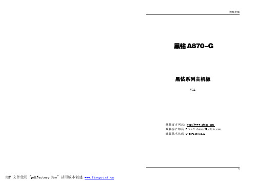
致铭主板黑钻A870-G黑钻系列主机板V1.1致铭官方网站:致铭客户邮箱:E-mail:*****************致铭技术热线:*************安全指导1.务必请仔细通读本安全指导。
2.务必请妥善保管本手册,以备将来参考。
3.请保持本设备的干燥。
4.在使用前,宜将本设备至于稳固的平面上。
5.机箱的开口缝槽是用于通风,避免机箱内的部件过热。
请勿将此类开口掩盖或堵塞。
6.在将本设备与电源连接前,请确认电源电压值,将电压调整为110V/220V 。
7.请将电源置于不会被践踏到的地方,并且不要在电源线上堆置任何对象。
8.插拔任何扩展卡或设备模块前,请都将电源线拔下。
9.请留意手册上提到的所有注意和警告事项。
10.不得将任何液体倒入机箱开口的缝槽中,否则会产生严重损坏或电路瘫痪。
11.如果发生以下情况,请找专业人员处理;a.电源线或插头损坏;b.液体渗入机器内;c.机器暴露在潮湿的环境中;d.机器工作不正常或用户不能通过本手册的指导使其正常工作;e.机器跌落或受创;f.机器有明显的破损迹象;12.请不要将本设备置于或保存在温度高于60℃(140℉)的环境下,否则 会对设备造成损害。
致铭主机板用户手册CTHIM MAINBOARD USER ’S MANUAL版权保护声明本手册为致铭科技的专用用户手册,我们非常小心的核对整理,但我们对于本手册的内容不保证完全正确。
同时因为我们的产品一直在持续的改良及更新,内部附图供参考,可能部分细节与实际产品有一点区别,在此手册中的一些规格或者参数都可能会存在过时而不适用的情况,这点致铭科技具有最终解释权。
主机板上的任何标帖请勿擅自撕毁,否则可能会影响到该款产品的质保期限的认定标准。
W ARNINGNever run the processor without the heatsink properly and firmly attached.PERMANENT DAMAGE WILL RESUL T!警告将散热器牢固地安装到处理器上之前,不要运行处理器,过热将永远损坏处理器!商标声明所有的品牌,产品,徽标,商标和公司名称都是属于商标或注册商标各自的拥有者。
- 1、下载文档前请自行甄别文档内容的完整性,平台不提供额外的编辑、内容补充、找答案等附加服务。
- 2、"仅部分预览"的文档,不可在线预览部分如存在完整性等问题,可反馈申请退款(可完整预览的文档不适用该条件!)。
- 3、如文档侵犯您的权益,请联系客服反馈,我们会尽快为您处理(人工客服工作时间:9:00-18:30)。
仪表 尺寸
95 x 328 x300
z “•”按键 改变设置参数的当前值的小数点位置。 “>”按键 改变设置参数当前闪烁数码管的位置。
z “∧” 按键 设置参数的当前闪烁数码管的值加 1。
z “∨” 按键 设置参数的当前闪烁数码管的值减 1。
z “短路复位”按键 当所检测 泄漏电流超出 20mA 时,仪器自动切断检测电 路,蜂鸣器长鸣,按下此键可重新进入正常测试状态。
险丝是否融断;
2、 仪器应小心轻放,不得摔掷;
3、 如仪器长期不用,应每三个月通电工作两个小时;
4、 仪器的贮存条件为:
a)温度:0-40℃;
b)湿度:<90% RH;
c)仓库内应保持干燥、无酸碱、易燃、易
爆等化学物质和其它腐蚀性气体。
八 装箱清单
序号
名
称
数 量 单位
1
数字电参数测量仪
2
仪表用电源线
四、仪表接线及使用方法
1、将电源插头插入本仪器 220V 电源插座中接通电源; 2、选择好工作方式,SOURCE 接测试电源 LOAD 接被测负载,
L 接相线 N 接零线,测试端接负载外壳;
3、 按下电源开关仪器显示为零
4、 将被测电路接通,此时显示测试电压和泄漏电流,自动
方式下相线零线电流值在两个窗口轮换显示;反之则一
>5M
45Hz~65Hz 0.25 秒/次 ±(0.25%读数+0.25%量程) 4 位有效数字
AC220V±15% 50Hz±2% 小于 5VA 环境温度:0~50℃;大气压力:86~106kPa 相对湿度:(20~90)%RH; 利用按键可设置时间,电流、电压报警上、下限, 仪表地址,波特率
3kg
3
仪表用 0.5A 保险丝
4
仪表使用说明书
5
仪表鉴定证书
ቤተ መጻሕፍቲ ባይዱ
6
保修单
7
开箱检验反馈单
8
打印电缆
9
串行口插件
10 上位机通讯软盘
11
仪表装架固定附件
12
13
1
台
1
根
2
只
1
份
1
份
1
份
1
份
根
张
注:其中 9、10、11 项根据不同的型号和客户要求决定是否
装箱
z “声音”按键 用来打开与关闭蜂鸣器的报警,按键上方的指示灯点亮 时表示蜂鸣器报警被屏蔽 。
z “手动/自动”按键 用于切换相线/零线泄漏电流的工作方式,处于手动状态 时,手动指示灯亮;反之自动指示灯亮,第四窗口显示切 换时间,并倒计时,时间到,自动完成相线零线的切换,
三 仪表使用说明
1 仪表前面板说明
3. 被测仪器必须放在与大地完全绝缘的台面上,且被测仪器 与大地没有任何连线;
4. 测试端外接引线时,应注意漏电保护; 5. 仪器应在推荐的工作条件下使用; 6. 不要超过仪器的测量极限使用; 7. 排除故障时须切断,并将电源插头脱开。
六.仪器的存贮、保养与维护:
1、 仪表开机时无显示,电源指示灯不亮,请检 查仪表电源是否接通,电源电压是否正常,保
循环执行。 z “相线/零线”按键
手动切换相线零线,相线时,第四窗口显示“L”零线显
8780 型数字电参数测量仪的前面板由电源开关部分、 显示窗口部分、按键部分组成。 z 显示窗口部分有四个显示窗口,四个显示窗口分别
显示电压、相线泄漏电流、零线泄漏电流、时间。
示“N”表示为零线,对应窗口显示各自的泄漏电流。
2.真有效值,对失真的波形同样有较高的测量精度。 3.具有可选的串行通讯口,可以实现远程通讯。 4.具有电压、电流上下限报警功能,具有声光报警功能。 5.具有短路保护功能。 6.量程自动切换功能。
选择要设置的参数
TIME
代表自动状态相线零线切换时间
A ¯ ¯ ¯ 代表电流上限
U ¯ ¯ ¯ 代表电压上限
U _ _ _ 代表电压下限
DELY
代表报警延迟次数(每次约 0.25 秒)
Addr
代表仪表地址(有串行口此参数才有效)
BPS
代表通讯波特率(有串行口此参数才有效)
二 主要性能及技术参数
型号 测量 范围 输入 阻抗 频率 显示 周期 误差 显示 方式 电源 功耗 工作 环境 参数 设置 仪表 重量
8780 电压 5-300V 电流:0.005-20.00mA
8780 泄漏电流仪
z “设置”按键
进入与退出参数设定状态。进入参数设定状态后,电压窗
口显示“SET”字符,第二窗口显示当前参数,第四窗口显示当前
参数值。
z “参数”按键
一 功能说明
8780 泄漏电流仪是采用单片机与模数转换技术设计的智 能型仪表。它利用单片机对模拟信号进行采样,并对采集到的 数据进行运算处理,将计算结果以数字的形式显示出来。具有 以下特点: 1.直观的数字显示及较高的测量精度,有效地避免读数误差。
个窗口固定显示某一个相值。另一个显示 0;
5、当被测负载泄漏电流超出设定值(设定值不等于 0)时,
8780 泄漏电流仪
蜂鸣器断续报警,电流窗口闪烁,超出 20mA 时,蜂鸣器 长鸣,显示“- - - -”,按复位键恢复正常测试。
五、使用注意事项
1. 仪器外壳必须接地良好,测试者应踏在绝缘垫上;
2. 测试电源的相线零线接入时,必须与仪器标注一致;