瑞典 IMO ACE 系列 螺杆泵 介绍、说明书
螺杆泵使用及现场说明书(相对详尽).

单螺杆抽油泵说明书一、工作原理地面驱动单螺杆抽油泵(以下简称螺杆泵)适用于稀油、稠油、高凝油及高含砂、高含气、含水油井的开采。
因其具有一次性投资少、泵效高、能耗低、结构简单、占地面积小、安装、作业、维修方便等一系列优点,成为石油开采业势在必行的更新换代产品。
螺杆泵主要由驱动装置、传动轴、泵转子和定子四大部分组成。
驱动装置为泵提供动力源;传动轴把地面的动力传递给井下的泵转子;泵转子是截面为圆形的单螺杆;泵定子是具有双螺旋线的内腔;在螺旋转子和定子之间有多个“S”形封闭空腔。
工作时驱动装置通过传动轴带动井下抽油泵的转子在定子衬套内作行星运动,转子和定子之间的“S”形空腔随转子的旋转面不间断地螺旋上升,由泵下面新形成的空腔完成液体的吸入,经转子的螺旋举升在泵上端排出,从而达到不间断连续采油目的。
因螺杆泵没有吸排液阀,具有抗砂卡、防气锁的功效。
二、产品的结构和组成地面驱动单螺杆抽油泵由驱动头、控制柜、泵体、油管锚、限位器、井下配件等组成。
三、产品的规格型号说明G LB—泵的总级数泵每转公称排量抽油杆传动螺杆泵型号表示示例:GLB120-36 即为每转公称排量120ml,36级的单螺杆抽油泵四、螺杆泵的性能特点1、地面装置结构简单,体积小,重量轻。
2、泵效高、节能、管理费用低。
泵效可达60% ~ 95%,是现有机械采油设备中运动阻力最小、能耗最省、效率最高的机械设备之一,是石油行业的更新换代产品。
3、适应粘度范围广,是可以开采稠油的较好的机械设备,一般来说,螺杆泵适合于输送粘度为8000mpa·S(50℃)以下的各种油品,因此多数稠油井都可以应用。
4、适应高含砂井,可输送含砂量达3%的砂浆。
5、适应高含气井,不会气锁,很适合于油气混输。
6、输出流量均匀,易于调节流量,通过改变地面驱动装置转速,很容易调节流量。
7、螺杆泵适应斜度不超过10°的油井,而且设备占地面积小,因此适合海上油田丛式井组,甚至水平井的采油使用。
干货分享:典型燃油供油单元的那些知识点,一网打尽

⼲货分享:典型燃油供油单元的那些知识点,⼀⽹打尽某三⼗万吨级VLOC的主机采⽤韩国⽃⼭WARTSILA:6RT-Flex 82T型共轨⼆冲程柴油机,⾼压油泵前的燃油压⼒在全负荷时要求≥7bar和≤10bar,燃油进机温度≤1500C,燃料油粘度范围13~17Cst,如使⽤轻质燃油,粘度应≥2Cst,回油压⼒则保持在3~5bar范围,为延长ICU (Injection control unit燃油喷射控制单元)寿命,对燃油的质量要求⾼;辅机则为上海齐耀的WARTSILA A6L20四冲程柴油机三台,使⽤重质燃料油时,进机处的粘度范围为12~24Cst,燃油温度应⼩于1500C,使⽤轻质燃油粘度要求≥1.8Cst。
主辅机共⽤奥拉莫林.上海(AURA MARINE)AMB-M-36-SS型供油单元,为保证主辅机的安全可靠运⾏,除对所⽤燃油进⾏适当的预处理外,供油单元的维护显得尤为重要。
奥拉莫林AMB-M-36-SS型供油单元主要由供油泵吸⼝滤器、两台供油泵、除⽓筒、两台增压泵、两组管式蒸汽加热器、⾃清/旁通滤器、粘度/温度控制单元、⼀台应急柴油泵、流量表和相关阀件等组成。
流程简图如下图:正压头的燃料油或柴油从燃油⽇⽤柜或柴油⽇⽤柜经三通阀进⼊400micr的供油泵吸⼝滤器,粗过滤后进⼊供油泵:供油泵为IMO制造的三螺杆泵,型号ACE038K3/NTBP,ACE代表系列号,038代表主动螺杆直径,K3代表此型号泵的投产年代,T代表泵轴封系列,P 代表安全阀结构形式。
泵排量7.45m3/h,马达功率3.5kw,3500r/min,安全阀设定压⼒10bar,泵浦⾃动切换压⼒设定为4bar,ACE泵适⽤的燃油粘度范围1.4~26Cst,满⾜主辅机使⽤要求。
ACE泵在泵腔设有排⽓旋塞,初次投⼊使⽤或泵检修后⾸次投⼊使⽤时,在泵吸⼊⼝为正压头的条件下,打开泵的进⼝阀和出⼝阀,拧松泵腔的排⽓旋塞2~3圈排⽓,直⾄油溢出后再拧紧,此外,ACE系列泵在轴封腔室专门配有⼀个如右图所⽰的润滑装置,通过此装置供润滑油⾄轴封腔室润滑轴封,润滑油量可通过顶部的调节盘调节,当油罐内的润滑⽤完后可重新充装。
干式真空螺杆泵 DP说明手册

DP系列螺杆式真空泵说明手册DRYP螺杆干式真空泵安全说明1、在阅读说明手册之前请不要操作设备;2、务必掌握足够的安全防护警告和使用必要的安全设备,以避免在设备安装和操作过程中的危险。
警告小心警告警告听从安全命令不要接触灼热表面设备运转时,请将身体和衣物远离设备操作设备过程中必须注意防护措施注意以上安全说明标签贴在你所购买的设备上,请勿移除、覆盖或弄脏;如果不正确遵守以上警告,有可能会导致操作人员的人身伤害。
安全l 、应避免泵的管道法兰受到过重的压力;2 、在无防护装备的情况下不要操作机器,而且不正确转向也会损坏泵;3 、操作过程中不要让泵的抽气口暴露大气;4 、当泵与电机连接时,不要进行维护操作。
前言说明手册描述了DP 型螺杆干式真空泵的操作和维护过程中需要了解和遵守的指示和警告。
泵的操作和维护人员务必仔细阅读该手册,以规范操作和维护,延长设备使用寿命。
1 .总体说明1.1概要螺杆干式真空泵通过两个旋转的螺杆,排出被吸入的气体形成真空,螺杆的端面轮廓形状包括了很多曲线.如阿基米德曲线、摆线曲线和圆弧,螺杆和螺杆之间、螺杆和泵体之间都存在一定的间隙,互不接触,平稳的旋转。
被抽气体被平稳顺畅的送到排气口排出泵外.泵的结构决定了泵油不会混入到被排出的气体中,电机的动力通过V 型皮带或联轴器驱动真空泵。
1.2结构●螺杆转子:螺杆转子是由高性能球墨铸铁铸造而成,由高精度数控机床加工,精密度高,正确的型线设计和高精度的加工是保证整机性能的关键。
螺杆经精密的动平衡试验。
●同步齿轮:同步齿轮是螺杆真空泵的最主要的部分之一,它用来保证两转子的同步旋转从而保持转子之间一定的间隙。
齿轮表面经高频淬火,然后由特殊的高精度磨削而成,噪音小。
●轴承:固定端采用的是双列角接触球轴承,伸缩端采用的是具有高负载能力的滚柱轴承。
这些轴承能够承受较高的转速和负载,以保证齿轮间和螺杆间的间隙。
●轴封:螺杆泵内部轴封采用的是双向唇型密封,可有效阻止流体的双向相互流动,保持流体成分一致。
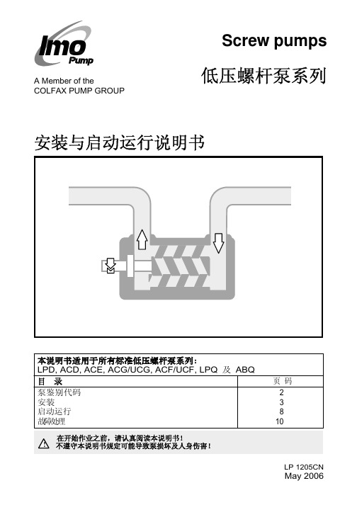
IMO泵安装启动中文说明书.
max 90° min 60°
Fig. 2 吊装泵
LP 1205CN May 2006
IMO AB, Telephone: + 46 8 50 622 800, Telefax: + 46 8 645 15 09 E-mail: info@imo.se, Web: www.imo.se
Fig. 11 液体截留
LP 1205CN
6
IMO AB, Telephone: + 46 8 50 622 800, Telefax: + 46 8 645 15 09
May 2006
E-mail: info@imo.se, Web: www.imo.se
压力表
推荐安装压力表用于监测泵的运行状态。压力表应安 装于便于观测的地方,并尽可能靠近泵的进出口法 兰。泵系列:ACE, ACG/UCG, ACF/UCF 及 LPQ, 其进出口法兰上均留有压力表联接口。
试压与清洗
在与泵连接之前,系统必须进行清洗及试压。若在清 洗试压时使用了腐蚀性的液体,如水等,则在清洗完 后,系统必须进行彻底的排空及干燥,以保护泵不受 腐蚀。
泄漏出的油液可能导致地面湿滑 ! 并引起人身伤害,应注意防滑!
Fig. 14 外部控制泄压阀
LP 1205CN
IMO AB, Telephone: + 46 8 50 622 800, Telefax: + 46 8 645 15 09
(2) B = 法兰安装 F = 脚支撑安装 Y = 垂直脚支撑安装
(3) E = 无泄压阀 G = 外部回流的阀 O = 较低压力的内回流的阀 P = 全部压力的内回流的阀
螺杆泵中文说明书-普
3.1 包装及运输............................................................................................................................................6 3.2 储存........................................................................................................................................................7
8 故障的发现及排除 ...................................................................................................................15
8.1 故障表..................................................................................................................................................15 8.2 如何根据出现的故障来寻找产生的原因 ..........................................................................................15
Omega FPU500系列双螺梭泵产品说明书

FPU500U Stainless Steel Rotor Assembly U I deal for Use in Sterile, Corrosive or General Operating Environments UF low Rates from 1.0 to 2280 mL/Min (36 GPH)U M ounts Directly onto OMEGAFLEX Motor or Compatible Pump Motor U E asily Stackable Mounting for Multichannel Pumping U T hree-Roller Geometry Reduces Pulsation and Improves Priming U P olysulfone Housing for Durability and Chemical ResistanceThe FPU500 Series peristaltic pumps from OMEGA ® offer exceptional simplicity, ease of use, and variable flow capability. A motor turns the pump’s rollers, which squeeze fluid through precision-bore tubing in a wave-like motion. The fluid does not come into contact with the pump; only the outside wall of the tubing does. This makes these pumps ideal for use in sterile, corrosive, or general fluid flow operating environments.The pump is self-priming and non-siphoning. When one section of the tube fatigues, simply move the tube along to an unused section and continue pumping. No tools are required to load the tube. A precision-molded tubing cavity provides the proper occlusion for the recommended tubing. A tube clamp holds the tubing securely in place. Tubing is easily changed without removing the pump.One pump can be used for many differentapplications, or you can mount two pumps onto the motor. The pumps work with a wide variety of OMEGAFLEX ® plastic tubing. Vinyl, FKM, Tygon, silicone, Santoprene, and Norprene ® tubing can be purchased in a broad range of sizes. The standard rotor assembly is made of stainless steel.The FPU500 pump can be purchased with an optional adaptor plate that can be used to mount the pump to a motor other than the FPU5-MT pump motor. The pump comes standard with 2 short mounting screws, used to mount one pump at a time. If you need to stack two pumps, order long mounting screws.SPECIFICATIOnSMaximum Back Pressure: 20 psi Maximum RPM to Prime: 100 RPM Tube Wall: 1.6 mm (1⁄16")Fluid Temperature Range:-46 to 149°C (-50 to 300°F)Dimensions, Pump: 102 H x 102 W x 57 mm D (4 x 4 x 21⁄4")O ptional Mounting Plate: 76 H x 64 W x 3.2 mm D (3 x 21⁄2 x 1⁄8")Weight, Pump: 408 g (14.4 oz)Optional Mounting Plate: 91 g (32 oz)Maximum Tubing Size: 8 mm (5⁄16")Maximum Tube Durometer: 65 Shore A Step 1: Snap Open with Easy Push-Button ReleaseStep 2: Loop Tubing OverRollers. no need to Thread!Step 3: Push to CloseSecure TubingOMEGAFLEX ®PErISTALTIC PuMPFPU500 shown smaller than actual size.L®U D igital Display of Flow Rate, RPM, Total Volume, Fluid Temperature (°C or °F), Flow Duration, or Tube ID U F low Rate 1.0 to 2280 mL/Min (10 to 600 RPM) Reversible U E asy-to-Read Display U R ear Panel Type K SMP Female Thermocouple Input U T achometer Feedback, ±0.5% Speed Control U A ccepts Two Pumps, One on Each Side or Two Stacked Together U M embrane Keypad for Easy Calibration U R emote Control Capabilities • Aux. In: Remote Start/Stop • Aux. Out: Remote Monitor U B uilt-In Electronic Braking and Reversing for Fast Stops and Directional Changes U A ccepts Metric or English Tube Sizes U D isplays Information in English, French, Spanish, German, or ItalianCalibrating the unit is easy with the user-friendly control software. Simply select a tubing size and the desired flow rate, and the pump motor locks in the required RPM. Select nominal calibration values stored in ROM (read only memory) or calibrate via gravimetric or flowmeter measurements. Fluid temperature may be displayed (using an optionalthermocouple probe). The last flow settings are stored in memory when the drives are shut off.SPECIFICATIOnSMotor: Reversible, 1⁄10 HP (75 W), 90 VdcDisplay: 16-character dot matrix LCD, 9 mm H (3⁄8") characters Power: 90 to 130 Vac, 1.5 A; 190 to 260 Vac, 0.8 ALine Cord: 1.8 m (6') with U.S. standard plug on 115 Vac units; European plug on 230 Vac unitsHousing: Painted sheet metal with rubber feet; units are stackableDimensions: 152 H x 254 W x 254 mm D (6 x 10 x 10")Weight: 8.2 kg (18 lb)Ordering Example: FPU5-MT-110, pump motor and, FPU500, peristaltic pump.FPU5-MT-110 pump motor, shown smaller than actual size, with two FPU500 pumps.The OMEGAFLEX ® FPU5-MT pump motor offers microprocessor control and a digital display, and is designed to be fully compatible with OMEGA’s FPU500 pump. No mounting plate is needed, just two mounting screws. A 1⁄10 HP (75 W) motor provides flow rates of up to 2280 mL/minute. The user enters values and controls all operations through a convenient membrane keypad. A dot matrix LCD provides for easy viewing.。
Omega PHP-200 210系列螺絮吸引泵用户指南说明书

e-mail:**************For latest product manuals:PHP-200/210 SERIESSolenoid Dosing PumpShop online atUser’s GuideIt is the policy of OMEGA Engineering, Inc. to comply with all worldwide safety and EMC/EMI regulations that apply. OMEGA is constantly pursuing certification of its products to the European New Approach Directives. OMEGA will add the CE mark to every appropriate device upon certification.The information contained in this document is believed to be correct, but OMEGA acceptsno liability for any errors it contains, and reserves the right to alter specifications without notice.WARNING: These products are not designed for use in, and should not be used for, human applications.Operating-/Settings Diagramy a l p s i ds u o u ni t n oC23Function DescriptionOperating modes Operating modes are selected using the MODE menu (depending upon identity code, someoperating modes may be absent)..“Analogue” operating mode: (Identity code, control variant: analogue current)The stroke rate is controlled via an analogue electrical signal via the “external control” terminal.Signal processing is pre-selected at the controller.“Manual” operating mode: (Identity code, control variant: manual, standard function)The stroke rate is controlled manually via the controller.“Contact” operating mode: (Identity code, control variant: external 1:1 / external with pulsecontrol)This operating mode offers the opportunity to make fine adjustments with small increase/decrease factors. Dosing can be activated by a pulse via the “external control” terminal or by asemiconductor element. With the “pulse control” option it is possible to pre-set a feed quantity(batch) or number of strokes (factor 0.01 to 99.99) via the control unit.“Batch” operating function: (identity code, control variant, external 1:1 / external with pulsecontrol)This operating mode offers the option of working with larger transfer factors (up to 65535).Metering can be triggered by pressing the P key or a pulse from the “external control” terminalvia a contact or semiconductor element. A batching quantity or number of strokes can be pre-selected via the control unit.Functions The following functions can be selected using the SET menu:“Calibrate” function:The pump can be operated in all operating modes including in calibrating mode. Thecorresponding continuous displays can show the actual feed quantity or the feed rate.Calibration is maintained within the stroke frequency range 0 - 180 strokes/ min. Calibration isalso maintained when a stroke frequency is altered up to ± 10 %.“Pressure level” function:It is possible to set different pressure levels.“Auxiliary frequency” function:It is possible to set a stroke rate in the SET menu, which may be activated via the “externalcontrol” terminal. This auxiliary frequency overrides all other pre-set stroke rate frequencies.“Flow” function:Stops the pump when the flow is insufficient. In the SET menu, the number of failed strokesis entered after which the pump will be turned off.The following functions are available as standard:“Float switch” function:Information on the liquid level in the feed chemical container is transmitted to the pump.This option requires the installation of a 2-stage float switch. This is connected to the “floatswitch” terminal.“Pause” function:The gamma/ L can be stopped by remote control via the “external control” terminal. Thepause” function operates only via the “external control” terminal.The following functions are activated by keystrokes:“Stop” function:The pump can be stopped by pressing the STOP/START key without disconnecting fromthe mains power supply.4Function Description“Prime” function:Priming (short term feed at maximum frequency) is activated by pressing both arrow keys at thesame time.Optional relay The pump has two connection options.“Fault indicating relay” option:In the event of fault signals, warning signals or float switch activation signals, connects anelectrical circuit to trigger alarm sirens etc. The relay is retrofitted via an aperture in the powerend.“Fault indicating and pacing relay” option:Along with the fault indicating relay, the pacing relay produces an electrical impulse for everystroke. The relay is retrofitted via an aperture in the power end.Function and errorindicators The operating and error status is shown via the three LEDs and the “error” indicator on the LCD(see also section 12):LCD indicator If a fault occurs “error” will appear along with an additional fault warning.LED indicator Operating indicator (green)This indicator is lit as long as the pump is operating correctly.Warning indicator (yellow)This warning light appears if the pump electronics detect a situation that could lead to afault, e.g. “liquid levels low 1st stage”.Warning indicator (red)This warning light appears if a fault occurs, e.g. “liquid levels low 2nd stage”.Hierarchy of operating modes, functions and fault statusesThe different operating modes, functions and fault statuses each have a differing effect onwhether and how the pump functions. These effects are given below:1.Prime2.Fault, stop, pause3.Auxiliary frequency4.Manual, analogue, contact, batchto:1.“Prime” can be activated in any pump status (as long as it is operable)2.“Fault”, “stop” and “pause” stop all system parts up to “prime”.3.The stroke rate of the “auxiliary frequency” always overrides the existing operatingstroke rate.567®891011。
瑞典IMO三螺杆泵资料大全(超全)

瑞典IMO三螺杆泵资料大全(超全)产品介绍IMO AB三螺杆泵三螺杆泵系列LPD/ACD/ACEACG/ACF/LPQE4/D4/D6/GA三螺杆泵的奠基人公司介绍1923年卡尔·蒙特卢斯先生开发了全世界第一台三螺杆泵的数学模型并与企业家朋特-英格斯特姆先生建立合作关系。
1931年IMO AB成立,取两人名字的首字母作为公司的名称。
此后的多年内,IMO AB公司不仅自己生产三螺杆泵,还在全球范围内发放产品专利许可生产权,其中包括很多著名的制泵公司。
今天,IMO已成为三螺杆泵的代名词。
历经70余载,位于瑞典首都斯德哥尔摩的IMO 公司以其优良的产品质量,过硬的可靠性和便捷的服务在业界蠃得了良好的口碑,并有几十万台IMO的三螺杆泵服务于各行各业。
作为三螺杆泵的奠基人,尽管蒙特卢斯先生的设计理念距今已70多年,但是IMO公司产品的可靠性、耐用性和低噪声,在该应用领域仍然无出其右者。
IMO AB/ALLWEILER同属COLFAX PUMP GROUP(美国科尔法泵业集团)旗下,是当今全球技术最先进和最大的螺杆泵制造商。
IMO螺杆泵系列1、LPD系列螺杆泵产品概述流量:2~24升/分钟最大压差:10巴适用范围:润滑、循环、输送用途LPD泵可用于多种流体介质,如润滑油、燃油、植物油、液压油以及其它液压流体、乙二醇、聚合物、乳化液和任何带有一定润滑特性的非侵蚀性流体。
典型的应用有:大型机器如柴油机、齿轮等的润滑。
柴油机、分油机和焚烧炉的燃油供给和循环。
驳运和装卸润滑油、燃油和燃料油。
2、ACD系列螺杆泵产品概述流量:11~45升/分钟(50HZ)最大压差:7巴适用范围:润滑、循环、输送用途ACD泵可用于多种流体介质,如润滑油、燃油、植物油、液压油以及其它液压流体、乙二醇、聚合物、乳化液和任何带有一定润滑特性的非侵蚀性流体。
典型的应用有:柴油机、齿轮、燃气/蒸汽轮机、液压透平、造纸机等的润滑。
大型机械和液压系统的冷却和过滤,向变压器中泵运变压器绝缘油。
- 1、下载文档前请自行甄别文档内容的完整性,平台不提供额外的编辑、内容补充、找答案等附加服务。
- 2、"仅部分预览"的文档,不可在线预览部分如存在完整性等问题,可反馈申请退款(可完整预览的文档不适用该条件!)。
- 3、如文档侵犯您的权益,请联系客服反馈,我们会尽快为您处理(人工客服工作时间:9:00-18:30)。
A C E 3 1122.03 G BACE3Std LineFlow volume:10 - 180 l/min Max differential pressure: 16 bar Applications: Circulation, lubrication and transferA C E 3 1122.03 G Bwww.imo.se21.1 FunctionalityThe Std Line (standard) ACE pump comes in two executions; Lube Line and Fuel Line. The main difference is the shaft seal design; (V-Seal) - optimized for light duty and (T-Seal) - heavy duty respectively.The ACE pump is used for a number of different fluids:Lubrication oil, fuel oil, vegetable oil, hydraulic oil and other hydraulic fluids, polymers, emul-sions and any non-aggressive fluid with sufficient lubricating properties.If requested, the ACE pump may be certified according to any of following classification societ-ies: DNV, BV, LRS, ABS, RS, GL, RINA, KR, NK, RMR or CCS.1.2 ApplicationsTypical applications are:- Lubrication of diesel engines, gears, gas and steam turbines, hydro turbines and paper ma-chines- Circulation for cooling and filtration in large machineries, hydraulic systems and transformer oil for insulation in transformers- As transfer pumps onboard vessels, in power plants, oil factories, refineries, tank farms etc - Fuel supply duties for engines - Supply and circulation of fuel oil1.3 InstallationThe pump is designed to be flange-mounted to its electric motor via a connecting frame and a flexible shaft coupling. By the angle bracket, the pump may be mounted horizontally or verti-cally.The ACE pump can also be mounted on valve blocks called T4 or T5.As standard, the pump is delivered including counter flanges (IMO AB design).For more information about installation, see Installation and Start-up instruction for low pres-sure pumps.A C E 3 1122.03 G Bwww.imo.se 3A C E 025N 3 N VB PPump seriesACE SizePower rotor diameter [mm]025, 032, 038LeadL and K = Low lead N = Normal lead D = High lead GenerationDesign generation 3Material in pump bodyN = Nodular cast ironShaft seal designV = Carbon/Stainless steel, elastomers in Viton (Lube Line)T = Silicon Carbide/Silicon Carbide, elastomers in Viton (Fuel Line)MountingB = Flange mountingValveP = Pressure relief valve with spring for max. 16 barSpecial designCode group omitted for standard design (A-number)A C E 3 1122.03 G Bwww.imo.se43.1 Pressure InformationPressure relief valveThe pump is equipped with an integral pressure relief valve with internal return, limiting the differential pressure across the pump and protecting the pump. Should the discharge line be blocked, the relief valve will open by the pressure.The valve is adjustable for different opening pressures. The value of the pressure limit can be set at the factory and should be adjusted at installation (see Installation & Start-up in-struction for low-pressure pumps).The maximum pressure accumulation varies with pump size, speed and viscosity, but will normally not exceed 4 bar.The valve has a maximum set pressure of 16 bar.Inlet pressureMinimum inlet pressure (suction capability) is dependent on fluid viscosity and rotation speed. It increases with decreasing viscosity and decreasing speed. Information about mini-mum inlet pressure for each individual duty case can be obtained from IMO AB or pump selection software WinPump.Maximum inlet pressure is 7 bar.Discharge pressureMaximum discharge pressure is 16 bar.Differential pressureMaximum differential pressure is 16 bar but reduced at low viscosities according to table belowViscosity [cSt] 1,4 2 6 10 >12Max. diff. pressure [bar] 6,9 8 12,4 15 16Refer to your IMO representative or use the pump selection software WinPump to determine the exact operating limits.3.2 Driver informationDriver typeThe pump is designed to be connected to an electrical motor via a flexible shaft coupling.SpeedThe maximum speed is 3600 rpm. For higher speeds, contact IMO AB.RotationThe pump is designed to operate in one rotational direction only, as standard clockwise when facing the shaft end. Pumps for CCW operation can be delivered on special request.For shorter periods of time, a few minutes for emptying a discharge line, the pump may be operated in reverse direction, provided the back pressure is limited to 3 bar.A C E 3 1122.03 G Bwww.imo.se 53.3 Sound levelTypical pump sound levels refer to free field conditions at a distance of 1 m from the pump. Noise of driver excluded in the quoted figures. The sound levels are measured at a discharge pressure of 5 bar, speed 2940 rpm and viscosity 40 cSt, according to ISO-3741.Size 025 032 038Sound level dB [A] 58 58 583.4 Moment of InertiaMoment of intertia [10-6 kgm 2]Size 025 032 038Value 49 72 1943.5 Fluid viscosityLube Line seal (Seal version code V):1,4 – 800 cSt for Lube and hydraulic oil Fuel Line seal (Seal version code T):1,4 – 3500 cSt for Fuel oilFor higher viscosity, contact IMO AB.3.6 Fluid temperatureLube Line (Seal version code V): -20 – +90 °C Fuel Line (Seal version code T): -20 – +155 °CA C E 3 1122.03 G Bwww.imo.se64.1 Ball bearingThe pump is fitted with an internal ball bearing which continously is being greased by the hand l ing media.4.2 Design materialModel Material pump Material rotor Material idler Material seal Material Elastomers ACE NV Nodular castironSteel, surface treated Cast iron, sur-face treated Carbon/Silicon carbideViton ACE NTNodular cast ironSteel, surface treatedCast iron, sur-face treatedSilicon carbide /Silicon carbideVitonA C E 3 1122.03 G Bwww.imo.se 7025L 025N rpm l/min kW l/min kW1470 10,0 0,313,5 0,4 1770 12,9 0,4 17,7 0,5 2950 24,5 0,9 34,1 1,0 3550 30,4 1,142,5 1,3032L 032Nrpm l/min kW l/min kW1470 22,8 0,535,9 0,8 1770 29,0 0,7 44,6 1,0 2950 53,3 1,3 79,0 1,9 3550 65,6 1,796,4 2,4038K 038N 038D rpm l/min kW l/min kW l/min kW1470 45,5 1,055,8 1,3 59,1 1,21770 57,1 1,3 70,5 1,7 76,2 1,52950 102,9 2,5 128,4 3,2 143,9 2,93550 126,2 3,2157,9 4,1178,2 3,6Typical performance values at 5 barFlow calculated at 26 cSt, power at 260 cSt.A C E 3 1122.03 G Bwww.imo.se8A C E 3 1122.03 G Bwww.imo.se9P o s N o D e n o m i n a t i o n1020 C o m p l e t e p o w e r r o t o r(112) B a l a n c i n g p i s t o n 113 K e y 122 B a l l b e a r i n g 125 S e c o n d a r y s e a l 125A R e t a i n i n g r i n g 202 I d l e r r o t o r 351 B a l a n c i n g b u s h 401 P u m p b o d y 440 R e t u r n v a l v e 451 S c r e wP o s N o D e n o m i n a t i o n 453 S c r e w 462 P l u g 462A S e a l i n g w a s h e r 463 P l u g 463A S e a l i n g w a s h e r 501 F r o n t c o v e r 506 G a s k e t 509 S h a f t s e a l 537 D e a e r a t i o n p l u g 537A S e a l i n g w a s h e r 551 R e a r c o v e r P o s N o D e n o m i n a t i o n556 G a s k e t557 P l u g 557A S e a l i n g w a s h e r 6000 C o m p l e t e v a l v e e l e m e n t (605) O -r i n g (608) V a l v e s p i n d l e (608A ) T e n s i o n p i n (6120) C o m p l e t e r e g u l a t i n g n u t (613) P i n (614) V a l v e p i s t o n (615) V a l v e s p r i n g7. D r a w i n g r e m a r k s :(1) S h a f t s e a l . E x e c u t i o n c o d e x T x x (2) A p p l i c a b l e f o r s h a f t s e a l e x e c u t i o n c o d e x T x x (3) S h a f t s e a l . E x e c u t i o n c o d e x V x x (4) A p p l i c a b l e f o r s h a f t s e a l e x e c u t i o n c o d e x V x x(5) R e m o v e d f r o m A u g u s t 2011N o t e s :- C o m p o n e n t s w i t h P o s N o w i t h i n p a r e n t h e s i s a r e p a r t s o f s u b a s s e m b l yA C E 3 1122.03 G Bwww.imo.se10A C E 3 1122.03 G Bwww.imo.se11D r a w i n g r e m a r k s :(1) I n l e t g a u g e . I S O G 1/8(2) O t h e r s i d e : O u t l e t g a u g e . I S O G 1/8(3) R e l i e f v a l v e . T u r n c l o c k w i s e t o i n c r e a s e o p e n i n g p r e s -s u r e(4) D e a e r a t i o n (2x )(5) F o r c o u n t e r fla n g e s d i m e n s i o n s s e e P u m p u n i t d i m e n -s i o n s p a g e 12N o t e s :- D i m e n s i o n s i n m m 1) T o l e r a n c e s I S O h 72) T o l e r a n c e s I S O j6A C E 3 1122.03 G Bwww.imo.se12A C E 3 1122.03 G Bwww.imo.se13D r a w i n g r e m a r k s :(1) I n l e t g a u g e . I S O G 1/8(2) O t h e r s i d e : O u t l e t g a u g e . I S O G 1/8(3) R e l i e f v a l v e . T u r n c l o c k w i s e t o i n c r e a s e o p e n i n g p r e s s u r e (4) C o n n e c t i n g f r a m e d r a i n a g e . I S O G 3/8(5) D e a e r a t i o n (2x )(6) S p a c e f o r d i s m a n t l i n g (7) B u t t w e l d c o u n t e r fla n g e s o f I M O d e s i g n n e c e s s a r y (8) A n g l e b r a c k e t f o r f r a m e s i z e F 215-F 265(9) A n g l e b r a c k e t f o r f r a m e s i z e F 165(10) A n g l e b r a c k e t f o r f r a m e s i z e F 130N o t e s :- D i m e n s i o n s i n m m - D i m e n s i o n s A , A 1, A C , A 2 a n d w e i g h t a r e a p p r o x i m a t e v a l u e s f o r B r o o k C r o m p t o n m o t o r s t y p e W U -DAA C E 3 1122.03 G Bwww.imo.se14aintenanceA bare shaft pump (Fig. 1) can be ordered with the accessories in fig. 2-8.Fig. 1 Bare shaft pumpFig. Set of counter flangesFig. 3 Connecting frameFig. 4 Electric motorFig. 5 Angle bracketFig 6. Shaft couplingFig 7. Valve blockFig 8. Gauge panelSpare parts for these pumps are easily available from stock. For detailed information andknow-how about service, see the Maintenance & Service Instruction for ACE3 pumps or contact IMO AB.A C E 3 1122.03 G Bwww.imo.se 15A C E 3 1122.03 G BIMO AB: P.O. Box 42090, SE 126 14 Stockholm, Sweden. Telephone: +46 8 50 622 800For latest updates, check:www.imo.se。