PCS-9647D_X_电抗器保护说明书
PCS- 9656D电弧光保护说明书

外部回路 当把装置输出的接点连接到外部回路时,须仔细检查所用的外部电源电压,以防止所连接的回
路过热。 连接电缆
小心处理连接的电缆避免施加过大的外力。
版权声明
版本:R1.20 P/N: ZL_DYBH0703.1309
PCS-9656D 电弧光保护装置
技术和使用说明书
前言
PCS-9656 电弧光保护装置
使用产品前,请仔细阅读本章节!
本章叙述了使用产品前的安全预防建议。在安装和使用时,本章内容必须全部阅读且充分理解。 忽略说明书中相关警示说明,因不当操作造成的任何损害,本公司不承担相应责任。
在对本装置做任何操作前,相关专业人员必须仔细阅读本说明书,熟悉操作相关内容。 操作指导及警告
残余电压 在装置电源关闭后,直流回路中仍然可能存在危险的电压。这些电压需在数秒钟后才会消失。
警示!
接地 装置的接地端子必须可靠接地。
运行环境 该装置只允许运行在技术参数所规定的大气环境中,而且运行环境不能存在不正常的震动。
额定值 在接入交流电压电流回路或直流电源回路时,请确认它们符合装置的额定参数。
电话:025-87178185、传真:025-8718208
我们保留在不事先通知的情况下进行技术改进的权利。
电子信箱:nr_techsupport@
南京南瑞继保电气有限公司 公司地址:中国南京江宁区苏源大道 69 号 邮编 211102 公司网址:
警告!
为增强或修改现有功能,装置的软硬件均可能升级,请确认此版本使用手册和您购买的产品相 兼容。
警告!
电气设备在运行时,这些装置的某些部件可能带有高压。不正确的操作可能导致严重的人身伤 害或设备损坏。
三相电源4杆可拔电路保护器产品说明书
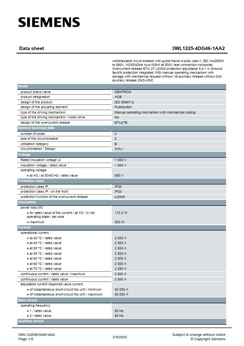
● at 415 V / rated value
● at 500 V / rated value
● at 690 V / rated value
breaking capacity maximum short-circuit current (Icu)
● at 415 V / rated value
● at 500 V / rated value
number of NC contacts / for auxiliary contacts
number of NO contacts / for auxiliary contacts
Suitability
suitability for use
Product details
product component
● at 690 V / rated value
Connections
arrangement of electrical connectors / for main current circuit
type of electrical connection / for main current circuit
Current operational current ● at 40 °C / rated value ● at 45 °C / rated value ● at 50 °C / rated value ● at 55 °C / rated value ● at 60 °C / rated value ● at 65 °C / rated value ● at 70 °C / rated value continuous current / rated value / maximum continuous current / rated value adjustable current response value current ● of instantaneous short-circuit trip unit / minimum ● of instantaneous short-circuit trip unit / maximum
PST 648U电抗器保护测控装置技术说明书V1.1

PCS-9692系列_X_说明书_国内中文_国内标准版_X_R2.21_(ZL_DYBH0601.1212)
BI3
204
开
入
BI4
205
BI5
206
BI6
207
BI7
208
BI8
209
Ia黄线
210
电
Ib绿线
211
流
Ic红线
212
输
In黑线
213
入
I0兰线
214
FGND白线 215
液晶 接口
PCS-9692N背板端子
1PWR
接地 FGND 101
电 PWR+ 102 源 PWR- 103
BO1常闭 104 BO12-com 105
第 1 章 概述 相关说明:PCS-9692M/N 为面板和本体分体结构,保护模块装在抽屉内,液晶模块安装在屏柜上, 两个模块通过连接线相连。 1.5.1.2 PCS-9692M/N 背板端子
1PWR
接地 FGND 101
电
PWR+ 102
源
PWR- 103
BO1常闭 104
BO12-com 105
输
204
入 Uc 205
206
BO4+ 207
BO4- 208
BO5+ 209
BO5- 210
BO6+ 211
BO6- 212
BI-COM 213
BI9 214
开 入
BI10
215
BI11 216
BI12 217 4 mA2+ 218 20 mA mA2- 219
3CPU
BI-COM1 301
BI1 302
电磁兼容:欧盟指令 89/336/EEC,EN50263:2000
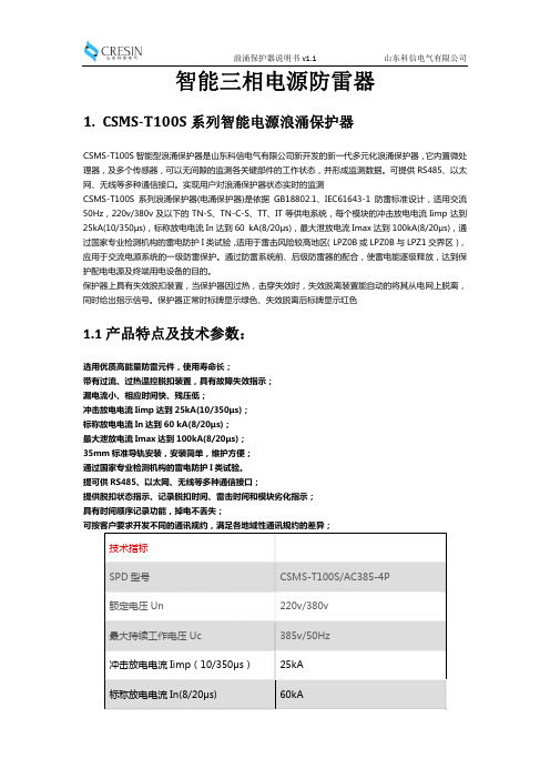
山东科信电气有限公司智能三相电源防雷器 least CSMS-T100S 系列智能 ла涌保护器说明
100kA
山东科信电气有限公司
保护水平 Up
≤1.8kV
响应时间
≤25ns
漏电流
≤10uA
前置熔断器
推荐 CSCB-T100 后备保护器
保护模式
L/N-PE
设计标准
GB18802.1
接口
接入导线截面
25mm2
接入接地线导线截面
35mm2
接线方式
端子接线
脱离器动作指示
浪涌保护器说明书 v1.1
山东科信电气有限公司
智能三相电源防雷器
1. CSMS‐T100S 系列智能电源浪涌保护器
CSMS-T100S 智能型浪涌保护器是山东科信电气有限公司新开发的新一代多元化浪涌保护器,它内置微处 理器,及多个传感器,可以无间隙的监测各关键部件的工作状态,并形成监测数据。可提供 RS485、以太 网、无线等多种通信接口。实现用户对浪涌保护器状态实时的监测 CSMS-T100S 系列浪涌保护器(电涌保护器)是依据 GB18802.1、IEC61643-1 防雷标准设计,适用交流 50Hz,220v/380v 及以下的 TN-S、TN-C-S、TT、IT 等供电系统,每个模块的冲击放电电流 Iimp 达到 25kA(10/350μs),标称放电电流 In 达到 60 kA(8/20μs),最大泄放电流 Imax 达到 100kA(8/20μs),通 过国家专业检测机构的雷电防护 I 类试验,适用于雷击风险较高地区(LPZ0B 或 LPZ0B 与 LPZ1 交界区), 应用于交流电源系统的一级防雷保护。通过防雷系统前、后级防雷器的配合,使雷电能逐级释放,达到保 护配电电源及终端用电设备的目的。 保护器上具有失效脱扣装置,当保护器因过热,击穿失效时,失效脱离装置能自动的将其从电网上脱离, 同时给出指示信号。保护器正常时标牌显示绿色、失效脱离后标牌显示红色
泽特电力保护器说明书

Eaton 199199Eaton Moeller® series PKZM0 Motor-protective circuit-breaker, 5.5 kW, 8 - 12 A, Feed-side screw terminals/output-side push-in terminals, MSCGeneral specificationsEaton Moeller® series PKZM0 Motor-protective circuit-breaker199199PKZM0-12-SPI32401508197283875 mm 102 mm 45 mm 0.322 kgVDE 0660 IEC/EN 60947 UL File No.: E36332 IEC/EN 60947-4-1 CSA File No.: 165628UL Category Control No.: NLRV ULCSA-C22.2 No. 60947-4-1-14 CSA Class No.: 3211-05 CSAUL 60947-4-1 CE UL CSAProduct NameCatalog Number Model Code EANProduct Length/Depth Product Height Product Width Product Weight CertificationsTurn buttonPhase-failure sensitivity (according to IEC/EN 60947-4-1, VDE 0660 Part 102)Motor protectionPhase failure sensitiveThree-pole 100,000 operations100,000 OperationsDIN rail (top hat rail) mounting optionalCan be snapped on to IEC/EN 60715 top-hat rail with 7.5 or15 mm height.40 Operations/hIII3Motor protective circuit breakerFinger and back-of-hand proof, Protection against direct contact when actuated from front (EN 50274)6000 V AC25 g, Mechanical, according to IEC/EN 60068-2-27, Half-sinusoidal shock 10 msAlso motors with efficiency class IE3Branch circuit: Manual type E if used with terminal, or suitable for group installations, (UL/CSA)≤ 0.25 %/K, residual error for T > 40°-5 - 40 °C to IEC/EN 60947, VDE 0660-25 - 55 °C, Operating rangeMotor starter combinations type MSC...Actuator type Features Functions Number of poles Lifespan, electricalLifespan, mechanicalMounting MethodMounting positionOperating frequencyOvervoltage categoryPollution degreeProduct categoryProtectionRated impulse withstand voltage (Uimp) Shock resistanceSuitable forTemperature compensationUsed withMax. 2000 m-25 °C55 °C25 °C40 °C40 °C80 °CDamp heat, constant, to IEC 60068-2-78 Damp heat, cyclic, to IEC 60068-2-301 x (1 - 6) mm²12 mm1.7 Nm, Screw terminals, Main cable50 Hz60 Hz12 A3 kW5.5 kW690 V690 V12 A18 kA, 240 V, SCCR (UL/CSA)18 kA, 480 Y/277 V, SCCR (UL/CSA) 18 kA, 600 Y/347 V, SCCR (UL/CSA) 65 kA, 240 V, SCCR (UL/CSA)65 kA, 480 Y/277 V, SCCR (UL/CSA)186 A, Irm, Setting range max.Basic device fixed 15.5 x Iu, Trip Blocks 0.5 HP 3 HP2 HP3 HPAltitudeAmbient operating temperature - minAmbient operating temperature - maxAmbient operating temperature (enclosed) - min Ambient operating temperature (enclosed) - max Ambient storage temperature - minAmbient storage temperature - maxClimatic proofing Terminal capacity (flexible)Stripping length (main cable)Tightening torqueRated frequency - minRated frequency - maxRated operational current (Ie)Rated operational power at AC-3, 220/230 V, 50 Hz Rated operational power at AC-3, 380/400 V, 50 Hz Rated operational voltage (Ue) - minRated operational voltage (Ue) - maxRated uninterrupted current (Iu)Short-circuit current rating (type E) Short-circuit release Assigned motor power at 115/120 V, 60 Hz, 1-phase Assigned motor power at 200/208 V, 60 Hz, 3-phase Assigned motor power at 230/240 V, 60 Hz, 1-phase Assigned motor power at 230/240 V, 60 Hz, 3-phase± 20% tolerance, Trip blocks7.5 HP10 HPPush-in terminals on output sideScrew terminals on feed side12 A12 AOverload trigger: tripping class 10 A 6.64 W0 W0 W0 WMeets the product standard's requirements.Meets the product standard's requirements.Meets the product standard's requirements.Meets the product standard's requirements.Meets the product standard's requirements.Does not apply, since the entire switchgear needs to be evaluated.Assigned motor power at 460/480 V, 60 Hz, 3-phase Assigned motor power at 575/600 V, 60 Hz, 3-phaseConnection Number of auxiliary contacts (change-over contacts)Number of auxiliary contacts (normally closed contacts)Number of auxiliary contacts (normally open contacts)Overload release current setting - min Overload release current setting - max Tripping characteristic Equipment heat dissipation, current-dependent PvidHeat dissipation capacity PdissHeat dissipation per pole, current-dependent PvidStatic heat dissipation, non-current-dependent Pvs10.2.2 Corrosion resistance10.2.3.1 Verification of thermal stability of enclosures10.2.3.2 Verification of resistance of insulating materials to normal heat10.2.3.3 Resist. of insul. mat. to abnormal heat/fire by internal elect. effects10.2.4 Resistance to ultra-violet (UV) radiation10.2.5 LiftingDoes not apply, since the entire switchgear needs to be evaluated.Meets the product standard's requirements.Does not apply, since the entire switchgear needs to be evaluated.Meets the product standard's requirements.Does not apply, since the entire switchgear needs to be evaluated.Does not apply, since the entire switchgear needs to be evaluated.Is the panel builder's responsibility.Is the panel builder's responsibility.Is the panel builder's responsibility.Is the panel builder's responsibility.Is the panel builder's responsibility.The panel builder is responsible for the temperature rise calculation. Eaton will provide heat dissipation data for the devices.Is the panel builder's responsibility. The specifications for the switchgear must be observed.Is the panel builder's responsibility. The specifications for the switchgear must be observed.The device meets the requirements, provided the information in the instruction leaflet (IL) is observed.Save time and space thanks to the new link module PKZM0-XDM32ME Motor Starters in System xStart - brochureProduct Range Catalog Switching and protecting motorsSwitching and protecting motors - catalogDA-DC-00004887.pdfDA-DC-00004917.pdfeaton-manual-motor-starters-pkz-dimensions-002.epseaton-manual-motor-starters-pkzm-pkzm0-dimensions-003.eps121X002121X042eaton-manual-motor-starters-pkz-dimensions.epsETN.PKZM0-12-SPI32.edzIL122024ZUWIN-WIN with push-in technologypkzm0_s32_pi.stppkzm0_s32_pi.dwg10.2.6 Mechanical impact10.2.7 Inscriptions10.3 Degree of protection of assemblies10.4 Clearances and creepage distances10.5 Protection against electric shock10.6 Incorporation of switching devices and components 10.7 Internal electrical circuits and connections10.8 Connections for external conductors10.9.2 Power-frequency electric strength10.9.3 Impulse withstand voltage10.9.4 Testing of enclosures made of insulating material 10.10 Temperature rise10.11 Short-circuit rating10.12 Electromagnetic compatibility10.13 Mechanical function BrochuresCatalogsDeclarations of conformity DrawingseCAD modelInstallation instructions Installation videosmCAD modelEaton Corporation plc Eaton House30 Pembroke Road Dublin 4, Ireland © 2023 Eaton. All Rights Reserved. Eaton is a registered trademark.All other trademarks areproperty of their respectiveowners./socialmedia。
PCS-9761直流滤波器保护技术说明书
5.4 软压板及整定说明...........................................................................................25 附录 A 差动保护和不平衡保护整定计算 ...................................................................27 附录 B 后备保护整定计算 ........................................................................................30 附录 C PCS-976D 高压直流滤波器保护装置调试大纲 ..............................................31 1. 试验仪器...........................................................................................................31 2. 试验注意事项....................................................................................................31 3. 保护装置的准备 ................................................................................................31 4. 开入量检查 .......................................................................................................31 5. 交流回路校验....................................................................................................32 6. 开出接点检查....................................................................................................33 7. 直流滤波器保护功能试验 ..................................................................................34 8. 注意事项...........................................................................................................36 9. 保护装置正常年检时的试验内容(建议) ..............................................................36
PCS-9621说明书

PCS-9621站用变保护测控装置
应用概述
PCS-9621适用于110kV以下电压等级的非直接接地系统或小电阻接地系统中的站用变或接地变
的保护及测控装置。
可组屏安装,也可在开关柜就地安装。
该保护装置可实现对断路器、隔离刀闸的分/合操作;同时能够对保护对象间隔单元的电压、电
流、功率等进行实时测量。
可以和监控系统进行通讯;通讯规约可选择IEC 60870-5-103或
IEC 61850。
•
数字化变电站功能
装置提供电子式互感器接口,支持IEC60044-8接口协议,借助多模光纤由合并单元引入电压量和电流量
合并单元传入的电压电流量的采样速率为4k/s或者5k/s。
支持IEC-61850通讯规约。
保护功能
三段复合电压闭锁过流保护
高压侧正序反时限保护
过负荷报警
两段定时限负序过流保护:其中Ⅰ段用作断相保护,Ⅱ段用作不平衡保护
高压侧接地保护:三段定时限零序过流保护(其中零序Ⅰ段两时限,零序Ⅲ段可整定为报警或跳闸)、零序过压保护、支持网络小电流接地选线
低压侧接地保护:三段定时限零序过流保护、零序反时限保护
低电压保护
非电量保护:重瓦斯跳闸、轻瓦斯报警、超温跳闸或报警、一路备用非电量跳闸、一路备用非电量跳闸或报警
闭锁简易母差GOOSE输出功能。
独立的操作回路及故障录波
测控功能
11路自定义遥信开入
Iam、Ibm、Icm、I0、UA、UB、UC、UAB、UBC、UCA、U0、f、P、Q、COSф共15个遥测量
一组断路器遥控分/合(选配方式至多可提供五组遥控)
事件SOE记录等。
- 1、下载文档前请自行甄别文档内容的完整性,平台不提供额外的编辑、内容补充、找答案等附加服务。
- 2、"仅部分预览"的文档,不可在线预览部分如存在完整性等问题,可反馈申请退款(可完整预览的文档不适用该条件!)。
- 3、如文档侵犯您的权益,请联系客服反馈,我们会尽快为您处理(人工客服工作时间:9:00-18:30)。
警示!
l 接地 装置的接地端子必须可靠接地。
l 运行环境 该装置只允许运行在技术参数所规定的大气环境中,而且运行环境不能存在不正常的震动。
l 额定值 在接入交流电压电流回路或直流电源回路时,请确认它们符合装置的额定参数。
本手册中将会用到以下指示标记和标准定义:
危险! 意味着如果安全预防措施被忽视,则会导致人员死亡,严重的人身伤害,或 严重的设备损坏。
警告! 意味着如果安全预防措施被忽视,则可能导致人员死亡,严重的人身伤害, 或严重的设备损坏。
警示! 意味着如果安全预防措施被忽视,则可能导致轻微的人身伤害或设备损坏。 本条特别适用于对装置的损坏及可能对被保护设备的损坏。
南京南瑞继保电气有限公司
技术支持,请联系: 电话:025-52107703、8008289967、4008289967 传真:025-52100770 或登陆网站:/ser_sup
公司总部:南京市江宁区苏源大道 69 号,邮编 211102 生产地址:南京市江宁区新丰路 18 号,邮编 211111 公司网址:
PCS-9647D 电抗器保护装置
技术和使用说明书
前言
PCS-9647D 电抗器保护装置
使用产品前,请仔细阅读本章节!
本章叙述了使用产品前的安全预防建议。在安装和使用时,本章内容必须全部阅读且充分理解。 忽略说明书中相关警示说明,因不当操作造成的任何损害,本公司不承担相应责任。
在对本装置做任何操作前,相关专业人员必须仔细阅读本说明书,熟悉操作相关内容。 l 操作指导及警告
1.1 应用范围 ............................................................................................................................. 1 1.2 功能配置 ............................................................................................................................. 1 1.3 性能特征 ............................................................................................................................. 2 1.4 订货须知 ............................................................................................................................. 3 1.5 装置执行标准 ...................................................................................................................... 3 第 2 章 技术参数............................................................................................................................... 5 2.1 电气参数 ............................................................................................................................. 5 2.2 机械结构 ............................................................................................................................. 6 2.3 环境条件参数 ...................................................................................................................... 7 2.4 通信端口 ............................................................................................................................. 7 2.5 型式试验 ............................................................................................................................. 8 2.6 认证..................................................................................................................................... 9 2.7 保护功能 ............................................................................................................................. 9 2.8 管理功能 ........................................................................................................................... 10 第 3 章 工作原理 ............................................................................................................................ 11 3.1 概述................................................................................................................................... 11 3.2 装置启动元件 .................................................................................................................... 11 3.3 差动保护 ........................................................................................................................... 12 3.4 过流保护 ........................................................................................................................... 13 3.5 过负荷保护........................................................................................................................ 13 3.6 零序保护(接地保护) ..................................................................................................... 14 3.7 非电量保护........................................................................................................................ 14 3.8 遥控、遥测、遥信功能 ..................................................................................................... 15 3.9 时间管理 ........................................................................................................................... 15 第 4 章 硬件描述 ............................................................................................................................ 17
l 印刷电路板 在装置带电时,不允许插入或拔出印刷电路板,否则可能导致装置不正确动作。
l 外部回路 当把装置输出的接点连接到外部回路时,须仔细检查所用的外部电源电压,以防止所连接的回
路过热。 lLeabharlann 连接电缆仔细处理连接的电缆避免施加过大的外力。
版权声明 © 2015 NR. 南京南瑞继保电气有限公司版权所有
警告!
为增强或修改现有功能,装置的软硬件均可能升级,请确认此版本使用手册和您购买的产品相 兼容。
警告!