JUKI操作手顺书
资料:18 B0 JUKI贴片机2070和2080操作规程

1.目的为使JUKI贴片机能够正常工作。
2.适用范围适用于JUKI2070、2080贴片机。
3.职责3.1生产部SMT组负责机器的使用和日常清洁/保养。
3.2生技课负责对机器的调校和维修。
4.操作规程4.1 工作前必须做到4.1.1操作者必须经培训合格,非合格人员严禁操作本设备。
4.1.2检查机械部分是否正常,各关键部件有无松动、损坏,各润滑部件是否有少油现象,检查各个传动皮带、链条有无损伤/打滑/松动。
4.1.3检查电气部分是否正常,检查电源线有无破损,整机是否可靠接地。
4.1.4检查气压是否正常(正常气压为0.4Mpa-0.7Mpa)。
4.1.5检查ATC周围有无异物。
4.2 以上确认无误后即可开机4.2.1将主电源的开关右旋至ON。
开机时应顺时针旋转开关4.2.2 WindowsXP启动,并显示KE2000的启动画面,机器初始化结束,画面显示返回原点,单击确定按钮,进行返回原点操作,机器启动成功,进入JUKI的KE2000画面。
作业前将机器进行预热20分钟4.2.3预热完毕,原点返回完成后便可以进行生产程式的编辑,在文件的下拉菜单中选择打开命令,选中生产所需的程式的名称,即可将程序打开。
4.2.4程式选择好后,以程序员的身分登录(在选项中点击变更用户组设置),点击程式编辑进入编辑画面,进行生产前相关数据(如基板数据、贴片数据、元件数据、吸取数据、图像数据)的确认:一. 基板数据:1.确认基板ID是否为所生产的PCB的名称或相应的注释.2.确定定位方式,我们一般采用外形定位3.确定基板配置(为单板还是矩阵)4.确认BOC.5.确认基板的外形(长,宽,高)坐标.6.核对BOC坐标二.贴片数据确认:1.确认元件ID.2.确认贴片的位置,可利用相机进行示教.3.确认元件帖片角度,根据元件在PCB上面的位置.4.用BOM确认元件是否准确.5.确认贴片头选择,一般为机器自动选择.6.标记,忽略,试打为默认,不需修改.7.层为4三.元件数据确认:(双击元件名称后弹出新的窗口)机器预热参数设置画面选择预热结束的条件预热的对象:轴或传送指定预热的时间(单位:时间)或次数1.确认元件名称.2.根据实际情况确认确认元件种类. 元件 0402 0603 0805 1206 电晶体 开关 小型芯片 大型芯片 料带宽度 单位(mm)8 8 8 8 8 12或16 12或16 12或165.在详述里面设置速度.四.吸取数据:(双击元件名称打开新的设置窗口) 1.确认元件角度. 2.供应位置选择前面 3,核对元件位置,料站号4.确认吸取位置,利用T-BOX 示教,确认以上确认无误,即可保存并退出编辑,变更用户组至操作员,打开基板生产菜单,按下“START1.用于联接装置与HLC 联机.2.START 按键,开始生产时使用此键.3.伺服马达开关.元件 0402 0603 0805 1206 电晶体 开关 小型芯片 大型芯片 X,Y 轴速度 快2 快2 快2 快2 快2 中 快2 慢 Z 轴吸取下降速度 快2 快2 快2 快2 快2 中 快2 慢 Z 轴吸取上升速度 快2 快2 快2 快2 快2 中 快2 慢 Z 轴贴片下降速度 快2 快2 快2 快2 快2 中 快2 慢 Z 轴吸取上升速度 快2 快2 快2 快2 快2 中 快2 慢 Θ测量 快 快 快 快 快 慢 中 慢 Θ其它 快 快 快快快慢中慢1 2 3 65 44.全轴回原点按钮.5.暂停开关:按此开关一次机器会暂停生产,如果再按一次的话机器将停止生产.此键在终止生产和模拟生产时使用.6.按此键一次,机器生产完一片基板进就会停止生产,如果再按将解除此模式.该开关用于紧急停止时使用,当机器出现异常或威及人身安全时按下此键,马达和其它驱动部分将会停止.待异常和危险解除后按白色箭头所指的方向旋动,即可恢复生产。
JUKI操作手顺书
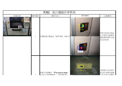
机器全图操作顺序操作方法注意事项JUKI 貼片機操作参照表操作圖例等待主机显示屏显示主菜单,方能操作键盘,期间操作会造成主机死机当机器无法正常回原点时,检测各镭射头是否清洁,用蘸有酒精的棉花棒轻轻擦拭镭射头镜面屏幕主菜單顯示“Will return to home position”後敲擊鍵盤上“ENTER”鍵,機器回原點21打開机器主電源由“OFF”開至“ON”位關閉狀態開啟狀態選‘OK’項3調出當前所需生產的程序文件名程序名按照生产需要分成红胶板(GLUE),锡膏板(SOLDER),双面板(DOUBLE)选择好程序后,進入“DATA INPUT”菜單,選擇“Pick data”項,用Camera 調節FEEDER 的中心坐標4原点时,检测各镭射头是否清洁,用蘸有酒精的棉花棒轻轻擦拭镭射头镜面Will return to home position”後敲擊鍵盤上“ENTER”鍵,機器回原點2将Camera 十字中心对准编带孔中心按此键選擇程序名選擇‘OK’選擇‘Pack使用小键盘上的左右键调节"X"轴坐标,上子键调节"Y"轴坐标,使元件十字中心在PCB 板上与其对应的PAD 的中心点上按过回流焊的实际状况对元件坐标进行微调选择好程序后,進入“DATA INPUT”菜單,選擇“Pick data”項,用Camera 調節FEEDER 的中心坐標46技術員根據檢驗員所反饋的信息適當調節元件坐標進入“PROD”菜單,選擇“Prod.mode”中“Trial”選項,試生產1片調節元件坐標5对准编带孔中心選擇‘Trial’調整元件坐標7調試好後,量產在量产前做好首检检查,并标识按过回流焊的实际状况对元件坐标进行微调6調節元件坐標END 左右上下。
juki设备操作流程

juki设备操作流程
Juki设备是一种高效的工业缝纫机,广泛应用于服装、家居用
品等行业。
操作Juki设备需要一定的技巧和经验,下面将介绍
Juki设备的操作流程。
首先,准备工作。
在操作Juki设备之前,需要检查设备是否正
常工作,包括线头是否正确安装、针眼是否干净等。
同时,准备好
需要使用的面料和线材。
接着,调整设备。
根据需要调整设备的线张力、针距等参数,
确保设备能够正常工作。
同时,根据需要更换适合的针头和线材。
然后,开始缝制。
将面料放在设备上,根据需要选择合适的缝
纫方式,开始缝制。
在操作过程中,要注意保持面料平整,避免出
现皱褶或拉扯。
在缝制过程中,要注意调整设备的速度和力度,确保缝制的质量。
同时,要及时检查缝线是否断裂或打结,避免影响缝制效果。
最后,完成缝制。
在缝制完成后,将面料从设备上取下,修剪
线头,整理面料。
同时,要及时清洁设备,保持设备的清洁和正常
工作。
总的来说,操作Juki设备需要熟练掌握设备的使用方法和技巧,
同时要注意细节,确保缝制的质量。
希望以上介绍能够帮助您更好地操作Juki设备。
JUKI使用说明书
3-1. 机器规格................................................................................................................................... 3-1 3-2. 原点粗调整 ............................................................................................................................... 3-2 3-3. 附属装置(选项) ......................................................................................................................... 3-3 3-4. 动作规格................................................................................................................................... 3-4 3-5. 注释 .......................................................................................................................................... 3-9
juki 7810e一体机节能单直驱使用说明书

一体机节能单直驱使用说明书All-in-one Direct Drive Instruction Book欢迎使用本公司产品,制衣行的正确投资选择!Welcome to use the our products,it is the right investment choices in garment industry!本说明书为本公司新研发的“一体机节能单抬压脚直驱控制箱”产品参考手册,请认真阅读此手册以更好运用本公司产品。
一、安全说明:General Safety Instructions1:电机电控接通电源时(开机状态)请不要把脚放在脚踏板上Do not put your feet on the pedals when the control box and motor is switched on(boot status)2:本产品请专业人士安装调试Let professionals to install and debug this product3:严禁在通电时打开控制箱与电机端盖Do not open the control box and the motor cover when energized4:换针,穿线或更换底线时请关闭电源Please turn off the power when changing the needle,threading or replacing the bottom line5:安装,拆卸维修时请拔掉电源插头During installation and removal service,please turn off the power and pull the plug6:翻抬缝纫机时请关闭电源Please turn off the power when turn lift sewing machine7:使用本产品请远离高频电磁波和电波发射器等,以免所产生的电磁波干扰伺服驱动器而发生错误动作。
VKFJ键盘操作说明书

Instruction ManualINDEX1 Product Introduction (1)1.1 Package Contents (1)1.2 Main Functions (2)1.3 Specification (3)2 Installation (4)2.1 Dimension (4)2.2 External Connection (5)3 Operation (7)3.1 Keyboard Self-detection (7)3.2 Joystick Operation (8)3.3 Key Operation (9)3.4 Menu Operation on LCD (10)3.4.1 Menu Operation Mode (11)3.4.2 Index of Menu (11)3.5 Menu Operation (12)3.6 Keyboard Short Commands (14)AppendixⅠAnalysis and Solution of Common Problem (15)Copyright Statement (16)1 Product Introduction1.1 Package ContentsKeyboard 1 pc Power supply 1pc 4Pin Line Pressing Terminals 1pc User manual 1pc1.2 Main FunctionsThe address range of PTZ or dome camera or decoder can be set from 0~255. At most, 128 devices can be connected in parallel.All input and output communication ports are lightning protection design and the anti-jamming ability is strong. The standard transmission distance is up to 1.2KM.Control all the functions of PTZ or dome camera, such as on / off of back light compensation.Set and run the preset point of PTZ or dome camera. 255 preset points are settable in all.Run PTZ or dome camera scan at a fixed speed or variable speed.Control PTZ or dome camera manually or automatically. Change factory default setting of special camera by adjusting camera menu.Control zoom, focus and aperture of camera manually.Control multiple PTZ or dome cameras at the same time.Built-in protocols are selectable.Built-in multiple languages OSD.Key sound on/off function.1.3 SpecificationProduct Vector Keyboard Power Supply DC12V+10%/50HZ 500mAOperatingTemperature-20℃~+55℃OperatingHumidity≤90% Non Condensing Communication RS-485Interface 4PIN Line Pressing TerminalsBaud Rate 1200bps, 2400bps, 4800bps, 9600bps, 19200bpsCommunication Protocol PELCO-D, PELCO-P,SAMSUNG,YAAN, SAECommunication between Camera and Keyboard One point to multi-pointsHalf-duplexJoystick Vector variable speed joystick Display LCD CommunicationDistance1.2KmControl CameraQuantity128OSD Menu EnglishDimension 220x130x10(mm)2 InstallationAfter open keyboard package, please keep the original packaging materials, so that when there is a problem, keyboard with original packaging materials can be sent back to the agent or the manufacturer for reparation. Non-original packaging material may lead to an unexpected transit damage, which may cause additional costs.2.1 DimensionFront side of KeyboardBackside of KeyboardPower Supply Interface: Connect to external stable voltage DC12V input through this interface.Communication interface: RS-485 communication interface. Indicator light of power: It shows the present power status. Light on means power connected well.Indicator light of communication interface: When keyboard connect to dome camera or PTZ, this light is on.2.2 External ConnectionPlease read the user manual carefully before any connection. Any wrong connection may cause the device damaged permanently. When you connect the device, please make sure the powers of all devices are off. Communication cable used between the devices connection must be twisted-pair cable with shielding. When cable is set up, high voltage line or other interfering line should be avoided as much as possible. Keyboard cannot be cross-connected when connecting with other communication devices. Anode must be to anode, cathode to cathode. As shown below:below:please make sure the address, protocol, baud rate of thekeyboard is set the same to the dome or PTZ camera. Otherwise, the dome or PTZ camera can’t be controlled.3 Operation3.1 Keyboard Self-detectionFig 3.1.1 Fig 3.1.2After power on, the keyboard take the following actions automatically:A. Self-detecting: The first line of LCD display shows“SYSTEM STARTUP”.The second line shows “<” and “<” increases successively till it fills the screen with one sound “di” as Fig 3.1.1.If sound is turned on, “<” increases successively with sound “di,di…” as Fig 3.1.1.B. After self-detection finishes: Get the current parametersautomatically and clear the contents of the second line onthe LCD display.The first line of LCD display shows “PELCO-D 2400 000”.They are communication protocol, baud rate, addressrespectively as Fig 3.1.2.3.2 Joystick OperationUsing joystick can control PTZ or dome camera’s rotation, pan-tilt direction and speed. Changing the tilt angle of joystick can adjust speed even.Vector joystick dimension is as below:Vector Joystick has three main functions as following:(1) Control dome camera rotation: Rocking the joystick in any direction, camera moves in appropriate direction. At the same time, the LCD displays "PTZ <<<<<". Controlling rocker of rotary speed of inclination can control the speed of the camera. More "<" displays on LCD screen, joystick tilts more, and the speed of camera is faster. Less "<" displays on LCD screen, joystick tilts less, and the speed of camera is slower.(2) Zoom Adjust (special function of 3D keyboard): Rotate the joystick grip to adjust focal length of the lens. Clockwise rotation of Joystick grip, zoom in and the image gets closer and larger; Counterclockwise rotation of joystick grip, zoom out and image gets farther and smaller.While rotating the joystick, the LCD displays "PTZ<<<<<".The number of "<" stands for the speed of zoom. More "<", zoom speed is faster. Less "<", zoom speed is slower.(3). The menu setting of controlled object: When setting menu, joystick up is to select previous menu and joystick down is to select the next menu. Joystick left or right can change parameters of the selected menu (as described in the LCD menu operation).3.3 Key Operation【Focus+】: Manual focus on far object. The far objects come clear and the near objects come blurring.【Focus-】: Manual focus on near object. The near objects come clear and the far objects come blurring.【Zoom+】: Zoom in to enlarge object.【Zoom-】: Zoom out the lens to larger view field. The object becomes smaller.【Iris+】: Increase aperture gradually. The picture becomes brighter.【Iris-】: Downsize aperture. The picture becomes darker. 【Setup】: Set key, [Setup]+number+[Enter] to set the preset point of the camera or set the short commands of thekeyboard(See 3.5).【Preset】: Run key, [Preset]+number+[Enter] to run the presetpoint.【Menu】: Menu key, to enter Menu.【Addr】: Address key, [Addr]+number+[Enter] to choose the communication address.【0】~【9】: Number keys [0], [1], [2], [3], [4], [5], [6], [7], [8], [9]. 【Clear】: Delete key, [Clear]+number+[Enter] to delete the preset point.【Enter】: Confirm key, to confirm the present operation.【Aux ON】: Aux ON.【Aux OFF】: Aux OFF.3.4 Menu Operation on LCDEnter the menu on LCD: Press【Menu】key to enter menu,as Fig 3.4.1.Fig 3.4.1Exit menu on LCD: Select random function keys except 【Menu】key to exit menu and enter corresponding operation. For example, press 【Focus+】to exit menu and enter focus setting. As Fig 3.4.2.Fig 3.4.23.4.1 Menu Operation ModeThere are two modes of menu operation:(1) Joystick operation: Joystick up and down to flip the menu.Joystick left and right + [Enter] to set theparameters of the menu.(2) Key operation: Press [2], [8] to flip the menu.Press [4], [6]+ [Enter] to set the parametersof the menu.Notice: When flipping to address page, [2], [8] can’t flip the menu page, and just function as number keys. [4], [6] can’t set parameters of menu, and just function as number keys.3.4.2 Index of MenuThe above menus are displayed in the second line on LCD. Only one menu is displayed at one time. The display mode is as below (e.g communication address):Menu Setting Range:PROTOCOL: PELCO-P/ PELCO-D/ SAMSUNG/ YAAN/SAELANGUAGE: ENGLISHSOUND: ON/OFFADDRESS: 000 ~255BAUD RATE: 1200/2400/4800/9600/19200 BPS3.5 Menu OperationWhen joystick and keys are operated at the same time, joystick operation is preferred.Rotating the joystick to any direction can exit the present setting page (except on menu page).When setting parameters in menu, pressing [Enter] can make the setting effective. The key [Enter] just store the latestchanged parameters of menu. For example,if you change protocol, address and baud rate in order, then press [Enter]. Only baud rate is changed successfully.When there is nothing in the second line on LCD as Fig3.5.1, number keys [2], [8], [4], [6] can be used as up, down, left and right keys to control PTZ or dome camera left and right rotation as the function of joystick. But the rotation speed is the fastest and no grades to select. Show as 3.5.2 (e.g key [2]).After entering menu, joystick has no function to control PTZ or dome camera. It can only be used as up or down to flip the menu page and left or right to change the parameters of menu. Number keys [0], [1], [3], [5], [7], [9] are invalid. [2], [8], [4], [6] are used as up, down, left and right keys. They are not used as number keys at this time. Their functions are just to flip the menu page but not to control PTZ or dome camera’s up, down, left or right rotation. Only after exiting menu and when there is nothing in the second line on LCD, they can control dome cameras up, down, left and right rotation.When setting [ADDRESS], number keys [0], [1], [3], [5], [7], [9] restore the number keys’ function. [2], [8], [4], [6] restore thenumber keys’ function and don’t have up, down, left and right functions.When pressing [Enter] after address setting on menu finishes, it will enter baud rate setting [BAUD RATE 2400]. When go back to [ADDRESS] again, the menu interface displays [ADDRESS 000]. The present set value can’t be seen. When exit menu, the first line on LCD displays the present communication address. Joystick up or down can exit address setting.Address range is 000-255. The number above 255 can’t be set.3.6 Keyboard Short CommandsCombination key: [Setup]+number+[Enter]Number Function700 Turn off sound701 Turn on sound812 Set baud rate to 1200bps824 Set baud rate to 2400bps848 Set baud rate to 4800bps896 Set baud rate to 9600bps819 Set baud rate to 19200bpsAppendixⅠ Analysis and Solution of Common ProblemIssue PossibleReasonSolutionCheck power cable connectionand connect it wellNothing onLCD after item is turnedon No powerMake sure power is DC12V Protocol iswrongCheck protocol of keyboard.Make sure it is the same to thedome or PTZ camera.Baud rateis wrongCheck baud rate of keyboard.Make sure it is the same to thedome or PTZ camera.Can’t control the target dome cameraAddress is wrongCheck address of keyboard. Make sure it is the same to the dome or PTZ camera.Notice: The above solutions of common issues are just for your reference. If there are some special issues, please contact your dealer to get technical support.Copyright StatementThis copyright merely belongs to the manufacturer. Without permission, please don’t plagiarize or copy the contents of this book in any form or by any means.The company follows the policy of continuous development. Therefore, the company reserves the right to modify or improve the products described in this manual without notice.The content of manual is offered according to the "current state". Unless applicable law specified, otherwise the company does not make any kind of clear or tacit assurance about the accuracy, reliability and contents of this manual. The company reserves the right to revise or recoup this manual at any time without notice.Distributed by :Challenger Security Products10 Sandersons Way Marton Blackpool FY4 4NBGeneral Enquiries : e.mail: ***********************.uk - web: Sales Tel No : 01253 791 888 Fax No : 01253 791887 Technical No : 01253 792898VKFJ V2。
JUKI贴片机操作规范

生效时间:2018/04/21版次:A1 页次:0/61. 目的为了使操作员能熟练掌握机器操作流程, 通过对设备的维护与保养,确保设备能正常运转, 提升设备使用率,保持良好的性能,延长设备的使用寿命.2. 范围适用贴片制程所有JUKI贴片机3.定义无4. 职责4.1设备的日常维护保养由操作负责执行.4.2 贴片组技术员及工程师负责贴片组部设备月,季度保养及故障维修.5. 作业流程5.1设备外观认识生效时间:2018/04/21版次:A1 页次:1/65.2开机步骤5.2.1请确认装置内部没有基板和工具等杂物.5.2.2向右旋转主开关,确认气压表(压力表)压力正常.生效时间:2018/04/21 版 次:A1页 次:2/65.2.3Windows XP 和主机软件依次起动后, 显示下列画面信息.选择「OK 」则开始返回原点.5.2.4生产前执行预热以确保在稳定状态下开始生产,设置预热条件,机器预热完成后才能进行生产.警告:1、执行返回原点时装置即开始运行.为避免受2、此外,请在确认装置内没有扳子等会磕碰贴片头等物体后,再执行返回原点生效时间:2018/04/21版次:A1 页次:3/6警告:1、按下[开始]开关后机器即开始运行2、为避免受伤,请绝对不要把手和头部伸进机器内部.5.3关机步骤5.3.1当生产完最后一片PCB时在按操作面板上的Origin键设备全轴回归原点.5.3.2保存生产程序,退出JUKI操作系统,退出Windows系统待LCD显示器显示黑色Windows时方可切断主机电源.5.4生产5.4.1在主菜单下点击“文件” 在主菜单下点击“生产”后选“基板生产”即可进入生产。
JUKI程序制作程序作业指导书

潍坊职业学院机电工程学院 编号: REV.JUKI贴片程序制作指导书承认 确认 制作机 种: XXXX电路板设备 仪器:JUKI2080贴片机图示 作业说明数据种类内容基板数据包括基板的外形尺寸和BOC 标记的坐标位置等有关基板整体的数据。
贴片数据包括贴片点的坐标和贴片元件名称等。
元件数据包括元件的尺寸、包装方式等定心时所需的数据吸取数据包括带状送料器及管状送料器等元件供应位置的数据。
图象数据包括QFP、BGA 等图象识别所需的数据。
1】从下面的 桌面画面 启动 编辑程序。
2】生产程序由5个项目构成。
挨次排开是:基板数据→贴片数据→元件数据→吸取数据→图象数据的顺序来制作。
注意事项:(1) 要编辑程序前要新建,在文件下面白色的图标在进行编辑的过程中要注意上一项目未完成时不能打开下一项目。
例)未完成“基板数据”时,不能打开“贴片数据”。
REV. 日期变更内容 担当确认潍坊职业学院机电工程学院 编号: Rev承认 确认 制作JUKI贴片程序制作指导书机 种: XXXX电路板 材料规格 见BOM表设备 仪器: JUKI2080图示 作业说明3】基板数据基板数据由“基本设置”、“尺寸设置”、“电路设置”3个项目构成。
A 基本设置: 输入基板的基本构成。
B 尺寸设置: 输入基板的详细尺寸。
按照“基本设置”中的指定改变显示项目。
C 电路配置: 指定电路的位置与角度的项目。
仅当“基本设置”中已设置“多电路非矩阵”时,方可选择。
4】基本设置基本设置中有7个项目。
操作过程中选择符合生产基板的相应的项目。
切换基本设置/尺寸设置/电路配置。
(竖的一排)切换基板数据/贴片数据/元件数据/吸取数据/图象数据。
(横向一排)A:定位方式1.定位孔基准: 当基板上有定位销插入孔时,通过在此孔中插入基准销来进行定位(定心)的方法。
2.外形基准: 对基板的外围进行机械性固定,以决定基板位置。
不使用基板定位孔。
B:基板配置1.单电路板:是指在一块基板上仅存在一个电路的基板。
- 1、下载文档前请自行甄别文档内容的完整性,平台不提供额外的编辑、内容补充、找答案等附加服务。
- 2、"仅部分预览"的文档,不可在线预览部分如存在完整性等问题,可反馈申请退款(可完整预览的文档不适用该条件!)。
- 3、如文档侵犯您的权益,请联系客服反馈,我们会尽快为您处理(人工客服工作时间:9:00-18:30)。
机器全图操作顺序操作方法注意事项
JUKI 貼片機操作参照表
操作圖例等待主机显示屏显示主菜单,方能操作键盘,期间操作会造
成主机死机
当机器无法正常回原点时,检测各镭射头是否清洁,用蘸有酒精的棉花棒轻轻
擦拭镭射头镜面
屏幕主菜單顯示“Will return to home position”後敲擊鍵盤上“ENTER”鍵,
機器回原點21打開机器主電源由“OFF”開至“ON”
位關閉狀態
開啟狀態
選‘OK’項
3調出當前所需生產的程序文件名程序名按照生产需要分成红胶板(GLUE),锡膏板(SOLDER),双面板(DOUBLE)选择好程序后,進入“DATA INPUT”菜
單,選擇“Pick data”項,用Camera 調節FEEDER 的中心坐標4原点时,检测各镭射
头是否清洁,用蘸有
酒精的棉花棒轻轻
擦拭镭射头镜面
Will return to home position”後敲擊鍵盤上“ENTER”鍵,機器回原點2将Camera 十字中心
对准编带孔中心
按
此
键
選擇程
序名選擇‘OK’
選擇‘Pack
使用小键盘上的左右键调节"X"轴坐标,上子键调节"Y"
轴坐标,使元件十字
中心在PCB 板上与
其对应的PAD 的中
心点上
按过回流焊的实际
状况对元件坐标进
行微调
选择好程序后,進入“DATA INPUT”菜單,選擇“Pick data”項,用Camera 調節FEEDER 的中心坐標46技術員根據檢驗員所反饋的信息適當
調節元件坐標進入“PROD”菜單,選擇“Prod.mode”中
“Trial”選項,試生產1片調節元件坐標5对准编带孔中心
選擇‘Trial’調整元件坐標
7調試好後,量產在量产前做好首检
检查,并标识按过回流焊的实际状况对元件坐标进
行微调
6調節元件坐標END 左
右
上
下。