T73随动转向大灯介绍 ok (NXPowerLite)
X-431_PRO_实测:2011_款途观2.0L_随动转向大灯设定操作方法

86·March-CHINA 栏目编辑:高中伟 ******************服务热线:4000 666 666实测车型一辆配置随动转向大灯的2011款途观2.0L 轿车,更换新的大灯后出现三个故障码:02656,左大灯电源输出端未编码;02657,右大灯电源输出端未编码;01539,大灯未设定。
仪表提示“随动转向大灯无功能,查阅用户手册”(图1),下面将使用X-431 PRO 对此车进行随动转向大灯设定操作。
图1 仪表提示随动转向大灯无功能图2 需要记录的汽车电脑控制单元编码图5 选择“001,调节位置&&调节自学习”图6 大灯电动机状态为“等待”图7 大灯电动机状态为“调整”图3 选择“11 控制单元编码”功能图4 输入汽车电脑控制单元编码注意事项1.车辆必须停在水平地面上。
2.将驻车制动器拉起。
3.打开点火开关。
4.关闭前自动大灯。
5.在更换新的自动大灯后,首先进行控制单元编码,再执行系统基本调整功能。
如果未更换新的大灯电动机或者大灯,只需执行系统基本调整功能即可。
如果中途中断程序,会出现“大灯未设定”的故障码,若要清除该故障码,必须完成整个操作程序。
操作步骤1.打开点火开关。
2.选择大众V27.11以上版本软件。
3.进入“系统选择”。
4.选择“55 大灯范围控制”系统。
5.记录汽车电脑控制单元编码:4244678(图2)。
6.选择“11 控制单元编码”功能(图3)。
7.输入图1中所示的汽车电脑控制单元编码“4244678”(图4),点击确定。
8.提示编码成功。
9.选择“04系统基本调整”,选择“按列表方式读取”,选择“001,调节位置&&调节自学习”(图5,如果选择“按通道方式读取”,输入通道号001),点击确定。
11.点击“调整”按钮,数秒钟后,电动机状态为“调整”(图7)。
12.等待20秒,待大灯电动机完成调整,打开大灯,手动调节灯光高度到合适的位置,完成系统基本调整。
XT300产品简介 (NXPowerLite)

QQ客户端
与QQ好友保持联系,随时随地方便您交流等 QQ 提供给您基本的社交功能:管理好友、查找好友、聊天记录、我的动态
开心和人人客户端
•与您的好友保持联系 •随时掌握同学同发生的新鲜事 •在第一时间与朋友分享感受及照片
XT300预置应用列表
应用 视频客户端 品味生活 浏览器 应用程序商店 SC Name 手机优酷 大众点评 UC浏览器 MOTO智件园 新浪微博 SNS客户端 人人客户端 开心客户端 品牌服务 应用 SC Name 迷你地图 同花顺 QQ QuickOffice 有道词典 超级水晶祖玛 四个休闲游戏 天气
竞品 对比
品牌 型号 5月市场份额 5月价格 上市时间 外形 网络 摄像头 显示 屏幕尺寸 重量 尺寸 外部存储器 FM收音机 WIFI 蓝牙 MP3 其他 滑盖 WCDMA 320万 万 TFT 320x240 3.1 120g 91x64x15.9 Micro SD Y Y Y Y Android、 aGPS、全键盘、 侧滑、 Flashback MOTO XT300 诺基亚 5800w 1.36% 2379 2010.03 直板 WCDMA 320万 16000K TFT 360x640 3.2 109g 111x51.7x15.5 Micro SD16384 Y WLAN Bluetooth 2.0 Y 诺基亚 E63 4.83% 1522 2009.08 直板 WCDMA 200万 16000K TFT 240x320 2.36 126g 113x59x13 Micro SD Y N Bluetooth 2.0 Y 三星 GT-B5310U 0.52% 2175 2010.03 侧滑 WCDMA 300万 16000K TFT 240x320 2.8 131.9g 105x56.8x15,68 Micro SD16384 Y WAPI/WIFI Bluetooth 2.1 Y 三星 GT-S7120U 0.24% 2075 2009.07 直板 WCDMA 300万 260K TFT 240x400 3.2 115g 109.5x57x12.7 Micro SD8192 N N Bluetooth 2.0 Y 索爱 J20 0.23% 2438 2010.04 滑盖 WCDMA 500万 16000K TFT 240x320 2.6 120g 102.0x49.5x16.0 Micro SD16384 Y N Y Y
尼康 Z 7II Z 6II 数码照相机使用说明书

A安全须知
“安全须知”包括重要安全使用说明。在使用照相机之前,请务必先阅读本部分内
容。有关详细信息,请参阅“安全须知” (பைடு நூலகம் xxxv)。
❚❚ 锂离子电池组
锂离子电池组是GB31241-2014 《便携式电子产品用锂离子电池和电池 组安全要求》对产品的定义名称。本资料也存在对锂离子电池组简称为 “电池”的情形。
ii
想立即进行拍摄时
❚❚ 拍摄 (0 56)并查看 (0 69)照片
1 将模式拨盘旋转至b。
2 半按快门释放按钮 (即轻轻按下快门
释放按钮,且在按到一半时保持不 动)进行对焦。
3 在不松开快门释放按钮的情况下,完
全按下该按钮拍摄照片。
4 查看照片。
想立即进行拍摄时 iii
包装内物品
请确认您照相机的包装中是否包含下列所有物品。
照相机控制............................................................................................................. 13 取景器 ............................................................................................ 13
2 插入存储卡 (0 45)。
3 安装镜头 (0 50)。
• 将镜头上的白点与照相机机身上的白点 对齐 (q),然后按照图示方向旋转镜 头 (w)。
• 您可在照相机上安装挂带。有关详细信
息,请参阅“安装挂带” (0 37)。
4 开启照相机并设定日期和时间
(0 52)。
T73 车型介绍 ok (NXPowerLite)
T73
车型介绍
四、转向系统(续) 转向系统(
可溃式转向柱
• 分级溃缩:转向柱上部最大溃缩量为70mm; • 下部收缩:转向柱下部最大收缩量为95mm。
25
T73 五、制动系统
行车制动
• • • •
车型介绍
型式:真空助力X型双回路ABS液压制动系统; 真空助力器直径:10寸; 助力比:慢速7.34,快速26.4; 制动总泵: BOSCH,缸径为Φ23.8mm,带EVA紧急辅助制动功能;
1845
815
587
1402
942
876
1818
841
584
1425
983
882
1865 14
T73 车型介绍 整车概述( 一、整车概述(续)
主要性能参数
项 最高车速 四档最低稳定车速 原地起步连续换档加速性能 0-100km/h 超车加速性能 四档 80-120km/h • 燃油消耗量: 60km/h等速 90km/h等速 120km/h等速 • 工况法燃油消耗量: 城市工况 市郊工况 混合工况 目 单 位 km/h km/h s DC7164DTB (BVM/BVA) 183 21 13.2 14.2 • 5.0 • 6.5 • 8.6 10.2 6.5 7.9 169 17 14.5 • 5.3 • 6.6 • 8.8 10.9 6.6 8.2 DC7204DTB (BVM/BVA) 201 23 11 11.9 • 5.5 • 6.8 • 8.7 11.1 6.4 8.1 195 12.5 12.2 6.0 7.1 9.0 11.3 6.7 15 8.4
备胎: 备胎:
23
T73 四、转向系统
车型介绍
• 转向器 齿轮齿条式转向机; 转向直径11m; 内/外轮最大转角为38.7°/32.5° / 38.7 /32.5 转向盘总圈数为2.88; • 转向盘 镁合金骨架,带喇叭开关; 1级车为发泡3幅条方向盘,2、3级车为真皮3幅条方向盘; 角度、高度可调(20mm); • 助力转向泵:叶片式机械液压助力转向油泵,随发动机转速改变助力大小
Chroma-Q Inspire XT Inspire Inspire Mini LED灯光产品说明
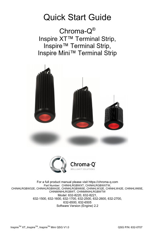
Quick Start GuideChroma-Q®Inspire XT™ Terminal Strip,Inspire™ Terminal Strip,Inspire Mini™ Terminal StripFor a full product manual please visit https://Part Number: CHINHLRGBWXT, CHINHLRGBWXTW,CHINHLRGBW32E, CHINHLRGBW42E, CHINHLRGBW65E, CHINHLW32E, CHINHLW42E, CHINHLW65E,CHINMINIHLRGBWT, CHINMINIHLRGBWTWModel: 632-8220, 632-8221,632-1500, 632-1600, 632-1700, 632-2500, 632-2600, 632-2700,632-6500, 632-6505Software Version (Engine) 2.21. OverviewThe Chroma-Q™ Inspire™ Terminal Strip LED house light features a single light engine with high powered LEDs (RGBW), a fully homogenized optic and controlled via the Inspire™ External Control Box. Through the Inspire External Control Box, the fixture can be controlled remotely through the ANSI E1.11 USITT DMX 512-A protocol.2. SafetyCaution 1. This product is for professional use only. It is NOT intended fordomestic or outdoor use.2. The bright flash of light during power-up and continuous strobe effect may cause epileptic seizure.3. This product must be used with safety cable.3. CablingFigure 1: Sample System DiagramFigure 2: Power & Data ConnectionsNote: The DMX cableconnected to the first Terminal Strip fixture from each Data Output of the External Control Box must be terminated with a 120Ω resistor. See Inspire Terminal Strip User Manual for details.Maximum DMX cable length from Data Out 1/2/3 to the 1st fixture must not exceed 500’/152m.Note:Refer to the marks on PCBLIVE NEUTRAL GROUNDP o w e r I n p u t : T e r m i n a l B l o c k H e a d e rData Plus Data MinusGround/ ShieldGround/ Shield Data Minus Data PlusData OutData InTo connect the wiring for power and control data:• The Power Input Connector Box (figure 3) is supplied with the fixture and is not attached. It must be mounted as described in the following stepsFigure 3: Power Connection: Connector BoxFigure 4: Power Connection: Light Fixture• Insert the power cable with the appropriate ½” NPT Connector or Cable Strain Reliefthrough the Connector Box (Figure 3). The hole on the connector box has a Suitable dimension to attach a ½” NPT connector on it. The Power Input Terminal Block Plug has three soft wires attached to it. Attach the provided wires to the wiring for the AC power input with Quick Connectors or Marret Connectors (Figure 3).• Put the Quick / Marret Connectors inside the Connector Box. Plug the wired Terminal Block Plug into the Power Input Terminal Block Header (Figure 4).• Connect the DMX control data cables from the Inspire External Control Box / another Inspire Light Fixture to the Terminal Block Plug. Ensure that the bare wire is not visible. Some insulation of the wire must be inside the hole. The maximum strip length is 4 mm (Figure 5). Plug Terminal Block Plug into the Terminal Block headers at the rear of the fixture (Figure 2 & 5).Strip Length 4mm MaxConnector Box ½” NPTConnector Quick ConnectorAC Power Input Cable POWER INPUT TERMINAL BLOCKPLUGConnector BoxPOWER INPUT TERMINAL BLOCK PLUGQuickConnectorFigure 6: Data Connection•Put the Connector Box in place and fasten the Connector Box with capacitive screw.Figure 7: Data In- First FixtureNotes:● IMPORTANT: Termination resistors (supplied with the External Control Box) are REQUIRED on first fixture in each data run (Figure 5) – see User Manuals for more details.● For DMX & data wires use Belden 9729 or CAT5e/6.● Max. cable distance from DATA OUT to first fixture must not exceed 152m/500 ft.● * Emergency Power is shown as an example only and may not be used on all projects.4. MountingA mounting bracket is built into the enclosure for overhead applications. Secure the fixture with a safety bond. A fixing hold is built into the enclosure. Optional accessories are also available for mounting Inspire light fixtures.5. OpticsThe Inspire XT is provided with a lens that delivers a beam angle of approximately 32°. Using a lens from the included Spread Lens kit will increase the beam to approximately 42° or 65°. For lens installation details, consult the instruction included with the kit.The Inspire Terminal Strip can be built with either Narrow, Medium or Wide lens. The beam angles are: Narrow: ~32°; Medium: ~42°; Wide: ~65°.The Inspire Mini Terminal Strip is built with wide lens with a beam angle of approximately ~65°.The Optional Spreader Lens Kit is available for changing the beam angle of any Inspire Light Fixture.6. ControlThe control functions are accessed through the Touch Screen display at the front panel of the Inspire External Control Box. The features of the Touch Screen Display are shown in Figure 8.Figure 8: Main screen of the External Control Box7. Further InformationPlease refer to the Chroma-Q Inspire TM manual for more detailed information. A copy of the manual can be found at the Chroma-Q website –https:///support/downloadsApprovals & DisclaimerThe information contained herein is offered in good faith and is believed to be accurate. However, because conditions and methods of use of our products are beyond our control, this information should not be used in substitution for customer's tests to ensure that Chroma-Q products are safe, effective, and fully satisfactory for the intended end use. Suggestions of use shall not be taken as inducements to infringe any patent. Chroma-Q sole warranty is that the product will meet the Chroma-Q sales specifications in effect at the time of shipment. Your exclusive remedy for breach of such warranty is limited to refund of purchase price or replacement of any product shown to be other than as warranted.Chroma-Q reserves the right to change or make alteration to devices and their functionality without notice due to on-going research and development.The Chroma-Q Space Force has been designed specifically for the lighting industry. Regular maintenance should be performed to ensure that the products perform well in the entertainment environment.If you experience any difficulties with any Chroma-Q products please contact your selling dealer. If your selling dealer is unable to help please contact ********************.Ifthesellingdealerisunabletosatisfyyourservicingneeds, please contact the following for full factory service:Outside North America: Tel: +44 (0)1494 446000 Fax: +44 (0)1494 461024 ********************North America:Tel: +1 416-255-9494 Fax: +1 416-255-3514 ********************For further information please visit the Chroma-Q website at https://chroma-com. Chroma-Q is a trademark, for more information on this visithttps:///trademarks.The rights and ownership of all trademarks are recognized.。
Power Train Lift 产品说明书

Sheet No. Issue Date:Rev E, May 4, 2012© 2005 SPX15Form No. 525699Parts List &Operating Instructions for:1595655 EISENHOWER DRIVEOWATONNA, MN 55060-0995 USA PHONE: (507) 455-7000TECH. SERV.: (800) 533-6127 FAX: (800) 955-8329ORDER ENTRY: (800) 533-6127 FAX: (800) 283-8665INTERNATIONAL SALES: (507) 455-7223 FAX: (507) 455-7063Shaded areas reflect the last revisions made to this form1 of 3Parts List & Operating Instructions Form No. 525699, Sheet 1 of 3, Back1 5287232 Wood Block 2 13575 4 Carriage Bolt3 133394 Washer (.474 ID, .926 OD) 4 10206 4 Hex Nut (7/16-14 UNC)5 5286796 Bolt (1-8 x 3.500)6 522270 8 Hex Nut, Reversible Lock7 166968 Press-in Grease Fitting 8 522268 8 Nylon Insert Hex Lock Nut9 522253 4 Frame Tube Weldment 10 528680 1 Bolt (.750-10 x 5.00) 11 16941 2 Lock Nut12 528681 1 Bolt (.750-10 x 4.00) 13 100054 Hex Head Cap Screw (1/4-20 x .50)14 10245 4 Lock Washer (.248 ID) 15 525698 1 1595 Logo/Warning Decal 17 522266 1 Riser Frame Weldment 18 522258 1 Riser Frame Weldment 19 523972 1 1595 Table Assembly 20 11253 12 Washer21 525974 2 Keeper Plate 22 525983 2 Bushing23 5269882 Hex Head Cap Screw(1-8 UNC x 3.750) 241110904Screw (10-24 x 1/2)SIDE VIEWItem Part No. No.No.Reqd.DescriptionItem Part No. No.No. Reqd.DescriptionRemoved Item #27 at last revision to this form.282930,31,32,333435,36,373839,4041423844BOTTOM VIEWSwivel lock on outside of unit.4525 525975 2 Glide Strip 26 522254 4 Wheel28 522250 1 Base Weldment 29 218297 8 Warning Decal30 10029 4 Hex Head Cap Screw31 10257 4 Washer (.349 ID, .692 OD) 32 10246 4 Lock Washer33 10201 4 Hex Nut (5/16-18 UNC) 34 523975 1 Motor Mount35 10079 16 Hex Head Cap Screw 36 12004 16 Washer37 10249 16 Lock Washer 38 526996 2 8" Swivel Caster39 222993 2 Socket Head Cap Screw (3/8 - 24 x 1/2) 40 10247 2 Lock Washer 41 526995 1 Cord Reel42 526997 1 8" Caster with Brake and Swivel 44 526989 1 8" Caster with Brake and Swivel 45 522505 1 Gear Pump(1.22 CC/Rev. 1725 RPM)46 665831084Cable ClampINCLUDED BUT NOT SHOWN306422 1 Strap AssemblySheet No. Issue Date:Rev E, May 4, 2012© 2005 SPXParts List & Operating InstructionsForm No. 5256992 of 3522505 Gear Pump561, 2, 34HYDRAULIC CIRCUITELECTRIC CIRCUIT522505 SCHEMATICSELECTRICAL SCHEMATICBLUE (LINE)BROWN (LINE)GREEN (GRD)RAISELOWERGREENBLACKWHITEB L AC KW H I T EGREEN (GRD)WHITEBLACK G R E E NW H I T E1254DOWNUPDOWNUPItem Part No. No.No.Reqd.Description1 532340 1 Controller2 532338 2 Magnet (Not shown)3 532339 2 2.5 x 6 mm Screw(Not shown)4 532336 1 Reservoir5 532337 1 O-ring6 532335 1 Filler Cap/Breather 75336361Control Decal7Parts List & Operating InstructionsForm No. 525699, Sheet 2 of 3, Back523972 – 1595 TABLE ASSEMBLY1 523969 1 Table Weldment2 523970 2 Threaded Trunnion3 523964 1 Threaded Rod4 523950 1 Table Base Weldment5 2221022 Screw, Hex Head(1"-8 x 1.5" Long, Grade 8) 6 11253 2 Washer7 522270 2 Reversible Lock Nut 8 206747 4 Thrust Bearing Washer 9 526998 4 Locking Collar 10 523966 1 Threaded Rod 11 10519 2 Set Screw 12 523965 2 Spacer 13 5239512BushingINCLUDED BUT NOT SHOWN523956 1 Table Tilt WeldmentRAM/HOSE/FITTING ASSEMBLY1 522260 1 Hydraulic Cylinder2 526993 1 Offset Tube Fitting 3 526991 1 Straight Fitting4 526992 1 Velocity Fuse5 525531 1 Hose Assembly 6106171Elbow7 RS-18000-131 1 Reusable Cable Tie 8 526990 190 Degree Elbow FittingINCLUDED BUT NOT SHOWN 20937 1 Vent Cap10527 1 O-ringRepair Replacement Kit for 522260531438 1 Seal KitItem Part No. No. No. Reqd.DescriptionItem Part No. No. No. Reqd.Description ItemPart No. No.No.Reqd.DescriptionSheet No. Issue Date:Rev E, May 4, 2012© 2005 SPX3 of 3Parts List & Operating InstructionsForm No. 525699• Study, understand, and follow all instructions before operating this device.• Wear eye protection that meets OSHA and ANSI Z87.1 standards.• No alterations shall be made to this product• Before using the lift, inspect the unit for leaks, or damaged, loose, or missing parts. Immediately replace cut, frayed, damaged hoses, and electrical cords.• Only use attachments and/or adapters supplied by the manufacturer.• Adequately support the vehicle before starting repairs.• Securely tighten the strap assembly around the component being lifted.• Do not exceed the rated capacity.• Do not lift or move a load that has a center of gravity extending beyond the wheels. Tipping can result in personal injury.• Do not move the lift while the load is raised. Always lower the load completely before moving or storing the load.• Carefully and slowly move a load on an incline or around a corner. Tipping can result in personal injury.• Use only on a hard, level surface.• Do not stand under a load that is supported by the lift.•The component must be securely held in place before it is removed from the lift.Safety PrecautionsOperating InstructionsRemoval1. Follow the vehicle manufacturer’s recommended service procedure for removal of the component.2. Position the power train lift under the vehicle. Connect the power cord to a 110V electrical outlet.3. Press the UP button on the hand-held control for the pump/motor and raise the lift to the load.4. A djust the wood blocks to fit the assembly, and tighten the nuts to secure the blocks in place.5. Turn the adjusting screws (items 3 and 10) to align the lift with the component. Raise the lift to the correct position.6. Place the strap assembly around the component, and tighten the strap securely to the hook holes.7. Remove any remaining bolts from the vehicle component.8. Completely lower the power train lift by pressing the DOWN button on the hand-held control.9.Move the lift and load out from under the vehicle.Installation1. Position the power train lift under the chassis.2. Raise the power train lift and turn the adjusting screws to align the component in the correct position.3. Follow the vehicle manufacturer’s recommended service procedure for installing the component.MaintenanceUse a good grade lubricant to regularly lubricate the pivot points, the adjusting screws, and the swivel casters.This page left blank intentionally.。
迅丽机顶闪光灯 Thinklite TT600 用户手册说明书
迅丽机顶闪光灯Thinklite Camera FlashINSTRUCTION MANUAL说 明 手 册中英文双语 / Chinese English Bilingual在使用本产品之前:请先仔细阅读本手册,以确保您能安全使用。
请保存好本手册以备将来查询参考。
Before using this product:Please read this user manual carefully in order to ensure your safety and the proper operation of this product. Keep for future reference.ForewordThank you for purchasing a GODOX product.TT600 camera flash adopts Godox wireless X system and 2.4G ratio transmission, which is compatible with AD360II-C、AD360II-N、TT685C、TT685N、X1T-C、X1T-N, etc. Fit all DSLR camera brands e.g. Canon, Nikon, Sony, etc.This TT600 camera flash features:• GN60 (m ISO 100, @200mm). Adjust from 1/1 to 1/128 in1/3rd stops• Built-in 2.4G wireless transmission to support transmitting andreceiving• High speed sync, wireless remote control, multi flash andmanual focus assist• Stable consistency and color temperature with good evenlighting• User-friendly LCD display & control panel- 19 -For Your Safety• Always keep this product dry. Do not use in rain or in dampconditions.• This product contains high-voltage electronic parts. Touching the high-voltage circuit inside it may result in electric shock. Do not disassemble. Should repairs become necessary, thisproduct must be sent to an authorized maintenance center.• Stop using this product if it breaks open due to extrusion,falling or strong hit. Otherwise, electric shock may occur if you touch the electronic parts inside it.• Do not fire the flash directly into the eyes (especially those of babies) within short distances. Otherwise visual impairmentmay occur. When taking pictures for babies, keep the flash unit at least 1 meter (3.3 feet) away from them. Using bounce flash to reduce light intensity is also recommended.• Do not use the flash unit in the presence of flammable gases, chemicals and other similar materials. In certain circumstances, these materials may be sensitive to the strong light emittingfrom this flash unit and fire or electromagnetic interference may result.• Do not leave or store the flash unit in places where the ambient temperature reads over 50°C (e.g. in automobile). Otherwisethe electronic parts may be damaged.- 20 -E l e c t r o n i c C a m e r aF l a s hThinklite Camera FlashConventions used in this Manual● This manual is based on the assumption that both the camera and camera flash’s power switches are powered on.● Reference page numbers are indicated by “p.**”.The Caution symbol gives supplemental information.- 21 -- 22 -Foreword For Your Safety Name of Parts Body Control Panel LCD PanelWhat’s in the Box of TT600?Separately Sold AccessoriesAttaching to a Camera Using the Flash Power Management Flash OutputZOOM: Setting the Flash Coverage M ModeMulti Mode: Stroboscopic Flash S1 Mode S2 ModeHi-Speed Sync TriggeringCustom Function----Focus Assist Beam Buzz FunctionWireless Flash Shooting: Ratio (2.4G) TransmissionWireless Control Function Sync TriggeringCustom Function----Sleep Function C.Fn Setting Custom FunctionsProtection Function Advanced Application Technical Data Maintenance192023262634353737Contents- 23 -● Body01. Catchlight Panel 02. Built-In Wide Panel (Retracted)03. Flash Head04. Optic Control Sensor 05. Focus Assist Beam(Long Keypress)06. Wireless Control Port 07. Sync Cord Jack 08. Hotshoe 09. Lock Ring10. Battery Compartment111218131415161717. <>Test Button / FlashReady Indicator(Long Keypress)06070809100504030201- 24 -● LCD Panel19. <M >Manual Flash Mode 20. <S1>S1 Slave Flash Triggering 21. <S2>S2 Slave Flash Triggering 22. <Multi >Multi/Stroboscopic31. Group223103● What’s in the Box of TT600?1. Flash unit2. Mini stand3. Protection case4. Instruction manual● Separately Sold AccessoriesThe product can be used in combination with the following accessories sold separately, so as to achieve best photography effects: Cells II high speed trigger, FT-16S power & trigger control, Car charger, Mini softbox, White & Silver Reflector, Honeycomb, Color gels, Snoot,etc.- 25 -- 26 -1.Power ManagementUse ON/OFF Power Switch to power the flash unit on or off. Turn off if it will not be used for an extended period of time. This flash unit has Sleep Function and will enter into sleep status when there is no operation for a long time. For Sleep Function setting, see the following instruction.2.Flash Output● Flash output can be varied from 1/128th power to 1/1 full power in 1/3 stop increments. To obtain a correct flash exposure, use a hand-held flash meter to determine the required flash output.● Adjust the power output by rotating Select Dial . The following table makes it easier to see how the stop changes in terms off/ stop when you increase or decrease the flash output:3. ZOOM: Setting the Flash Coverage- 27 -Using the Flashtrigger hot shoe for firing. Before shooting, adjust the flash power output. When the camera’s shutter is pressed, the flash will fire synchronously. Slave triggering mode is not available in M mode.flashes is fired. It can be used to capture multiple images of a moving subject in a single photograph. You can set the firingCalculating the Shutter SpeedDuring stroboscopic flash, the shutter remains open until the firing stops. Use the provided formula to calculate the shutter speed required to capture the full sequence of flashes:Number of flashes / Firing frequency = Shutter speed For example, if the number of flashes is 10 and the firing frequency is 5 Hz, the shutter speed should be at least 2 sec.Note:● Stroboscopic flash is most effective with a highly reflectivesubject against a dark background.● Using a tripod and a remote switch is recommended.● A flash output of 1/1 or 1/2 cannot be set for stroboscopic flash.● Stroboscopic flash can be used with “buLb”.Press the Mode Selectionitem blinks.is respectively applicable to manual flash environment.● In S1 mode, the flash unit will fire- 29 -● In S2 mode, the flash unitcan function as a slave flash for creating multiple lighting effects. It is applicable when using a TTL master flash.● In S2 mode, the flash unit will ignore a single “preflash” from● To entermode, long press● To exit mode, press Mode ● In <> hi-speed sync triggering mode, you can use a hi-speed sync trigger to have your flash unit synchronized with all shutterspeeds of cameras (max. 1/8000 second, up to your camera). This is convenient when you want to use aperture priority for fill-flash portraits.Note:*Hi-speed sync triggering mode is effective only when the flash unit is used together with the following flash triggers.1. Hi-speed sync trigger, e.g., Godox Cells II transceiver.2. TTL wireless flash trigger X1C 3. TTL wireless flash trigger X1N*Hi-speed sync triggering mode is not available when TT600 is mounted onto the camera.Godox Cells II transceiver(Optional )TTL wireless flash trigger X1C /X1N (Optional )- 30 -pop is fired. The time between the last fire and the auto shutdown of focus assist beam is calledNo-Flash Time. The time is user adjustable and set to 10 seconds Then press “SET” button to enter “FC” mode. The LCD paneldisplays “FC” (Auto shutdown of ● When the buzzer is turned on, 11. Wireless Flash Shooting: Ratio (2.4G) TransmissionMaster mode, groups can be selected from M/A/B/C/D/E; while in Slave mode, groups can be selected from A/B/C/D/E.● As TT600 adopts Godox wireless X system, it is compatible with AD360II-C、AD360II-N、TT685C、TT685N、X1T-C、X1T-Nwireless control, etc.● See the picture below:12. Wireless Control Function● The flash unit is built in with a Wireless Control Port (6) so that you can wirelessly adjust the power level of the flash and control the on-or-off of your flash, focus assist beam and buzzer, as well as trigger the flash.● To control the flash wirelessly, you need a Godox FTseries remote control set (on-camera and on-flash).(6) on the flash and insert the transmit endinto the camera hot shoe. Settings madeon the hotshoe-mounted transmit andreceive ends will bewirelessly communicated tothe flash. Then you canpress the camera shutter-release button to triggerthe flash. You can also holdthe transmit end at hand tocontrol your off-cameraflash.13.Sync Triggeringentering Sleep Mode is 10 minutesby default. Rotate Select DialTransmission distance isabout 100 meters- 31 -● When the flash enters sleep mode, the LCD panel displays a “Z z” icon.● To wake up the flash unit, press any button on the flash unit, or press the camera release button, or press the trigger TESTbutton.Note:The idle time before entering Sleep Mode is recommended to set short. This can ensure a longer battery life.15. C.Fn Setting Custom Functions- 32 -- 33 -1. Over-Temperature Protection● To avoid overheating and deteriorating the flash head, do not fire more than 30 continuous flashes in fast succession at 1/1 fullpower. After 30 continuous flashes, allow a rest time of at least 10 minutes.● If you fire more than 30 continuous flashes and then fire moreflashes in short intervals, the inner over-temperature protection function may be activated and make the recycling time about 10 to 15 seconds. If this occurs, allow a rest time of about 10minutes, and the flash unit will then return to normal.the LCD display.Number of flashes that will activate over-temperatureNumber of flashes that will activate over-temperature protection- 34 -2. Other ProtectionsThe system provides real-time protection to secure the device andAdvanced Application● Bounce FlashBy pointing the flash head toward a wall or ceiling, the flash will bounce off the surface before illuminating the subject. This can soften shadows behind the subject for a more natural-looking shot. This is called bounce flash.To set the bounce direction, hold the flash head and turn it to a satisfying angle.- 35 -Advanced Application● Creating a CatchlightWith the catchlight panel, you can create a catchlight in the subject’s eyes to add life to the facial expression.● Using the Wide PanelPull out the built-in wide panel to enlarge the flash lighting range, so as to get more softened and natural lighting effect.Pull out the wide panel andplace it over the flash head asshown. The flash coverage willthen be extended to 14 mm.● The catchlight panel will comeout at the same time. Pushthe catchlight panel back in. - 36 -Technical DataMaintenance-Shut down the device immediately should abnormal operation be detected.-Avoid sudden impacts and the lamp should be dedusted regularly. -It is normal for the flash tube to be warm when in use. Avoidcontinuous flashes if unnecessary.-Maintenance of the flash must be performed by our authorizedmaintenance department which can provide original accessories. -This product, except consumables e.g. flash tube, is supportedwith a one-year warranty.-Unauthorized service will void the warranty.-If the product had failures or was wetted, do not use it until it isrepaired by professionals.-Changes made to the specifications or designs may not bereflected in this manual.- 37 -深圳市神牛摄影器材有限公司GODOX Photo Equipment Co., Ltd.地址/Add: 深圳市宝安区福永镇福洲大道西新和村华发工业园A4栋Building A4, Xinhe Huafa Industrial Zone, Fuzhou RD West, Fuyong Town, Baoan District, Shenzhen 518103, China电话/Tel: +86-755-29609320(8062) 传真/Fax: +86-755-25723423邮箱/E-mail:***************705-TT6000-00 Made In China。
AXIS P3727-PLE 4x2 MP 多方向无人机相机 360° 切换视角与光线自适应说明书
DatasheetAXIS P3727-PLE Panoramic Camera4x2MP multidirectional camera with IR for360°coverageAXIS P3727-PLE offers four channels with2MP per channel at30fps.This multidirectional camera allows for flexible positioning of four varifocal camera heads.Each head can be controlled individually to capture scenes in four directions in wide-angle or zoomed-in views.It includes360°IR illumination with individually controllable LEDs and an automatic IR cut filter.Plus,remote zoom and focus capabilities ensure fast and accurate installation.AXIS Edge Vault protects your Axis device ID and simplifies authorization of Axis products on your network.Furthermore,AXIS Object Analytics offers highly nuanced object classification and reliable detection with fewer false positives.>4*2MP at30fps per channel>360°IR illumination with individually controlled LEDs>AXIS Edge Vault and TPM module>AXIS Object Analytics on one channel>Edge storage with2*microSD card slotsAXIS P3727-PLE Panoramic Camera CameraImage sensor4x1/2.8”progressive scan RGB CMOSLens Varifocal,3–6mm,F1.8–2.64x1080p capture mode:Horizontal field of view:96°–49°Vertical field of view:53°–27°Diagonal field of view:113°–55°Fixed iris,IR corrected,remote zoom and focusDay and night Automatically removable infrared-cut filterMinimum illumination With Forensic WDR and Lightfinder: Color:0.17lux at50IRE,F1.8B/W:0lux at50IRE,F1.8Shutter speed1/32500s to2s with50Hz1/32500s to2s with60HzCamera angleadjustmentPan±90°,tilt+25to+95°,rotation–5to+95°,twist±20°System on chip(SoC)Model ARTPEC-7Memory1024MB RAM,512MB FlashComputecapabilitiesMachine learning processing unit(MLPU)VideoVideo compression H.264(MPEG-4Part10/AVC)Baseline,Main and High Profiles H.265(MPEG-H Part2/HEVC)Main ProfileMotion JPEGResolution4x1920x1080(4x2MP)to4x640x360Frame rate Up to25/30fps(50/60Hz)Video streaming Multiple,individually configurable streams in H.264,H.265and Motion JPEGAxis Zipstream technology in H.264and H.265Controllable frame rate and bandwidthVBR/ABR/MBR H.264/H.265Low latency modeImage settings Saturation,contrast,brightness,sharpness,Forensic WDR,white balance,day/night threshold,tone mapping,exposure mode,exposure zones,compression,rotation:0°,90°,180°,270°including Corridor Format,mirroring,dynamic text and imageoverlay,polygon privacy masksAudioAudio input/output Two-way audio connectivity via optional AXIS T61Audio and I/O Interfaces with portcast technology.A30W midspan or higher is required between AXIS T61Audio and I/O Interfaces and AXIS P3727-PLE.NetworkIP address One IP address for all channelsSecurity IP address filtering,HTTPS a encryption,IEEE802.1x(EAP-TLS)a network access control,user access log,centralized certificatemanagement,signed video,Axis Edge Vault,Axis device ID,secure keystore(CC EAL4certified),TPM(FIPS140-2certified)Network protocols IPv4,IPv6USGv6,ICMPv4/ICMPv6,HTTP,HTTPS a,HTTP/2, TLS a,QoS Layer3DiffServ,FTP,SFTP,CIFS/SMB,SMTP,mDNS (Bonjour),UPnP®,SNMP v1/v2c/v3(MIB-II),DNS/DNSv6,DDNS, NTP,NTS,RTSP,RTP,SRTP/RTSPS,TCP,UDP,IGMPv1/v2/v3,RTCP, DHCPv4/v6,SSH,LLDP,CDP,MQTT v3.1.1,Secure syslog(RFC 3164/5424,UDP/TCP/TLS),Link-Local address(ZeroConf)System integrationApplication Programming Interface Open API for software integration,including VAPIX®and AXIS Camera Application Platform;specifications at One-click cloud connectionONVIF®Profile G,ONVIF®Profile M,ONVIF®Profile S and ONVIF®Profile T,specification at Onscreen controls IR illumination Autofocus Privacy maskEvent conditions Audio:audio clip playingDevice status:above operating temperature,above or belowoperating temperature,below operating temperature,casingopen,IP address removed,network lost,new IP address,storagefailure,system ready,within operating temperatureEdge storage:recording ongoing,storage disruption,storagehealth issues detectedI/O:manual trigger,virtual inputMQTT subscribeScheduled and recurring:scheduled eventVideo:average bitrate degradation,day-night mode,live streamopen,tamperingEvent actions Record video:SD card and network shareMQTT publishUpload of images or video clips:FTP,SFTP,HTTP,HTTPS,networkshare,and emailNotification:email,HTTP,HTTPS,TCP,and SNMP trapOverlay text,play audio clip,day/night mode,status LED,IRillumination,MQTTBuilt-ininstallation aidsPixel counter,remote focus,remote zoomAnalyticsAXIS ObjectAnalyticsObject classes:humans,vehiclesTrigger conditions:line crossing,object in areaUp to10scenariosMetadata visualized with trajectories and color-coded boundingboxesPolygon include/exclude areasPerspective configurationONVIF Motion Alarm eventAvailable for one channelMetadata Object data:Classes:humans,faces,vehicles,license platesConfidence,positionEvent data:Producer reference,scenarios,trigger conditions Applications IncludedAXIS Object Analytics,AXIS Video Motion Detection,AXIS Motion Guard,AXIS Fence Guard,AXIS Loitering Guard,active tampering alarmSupport for AXIS Camera Application Platform enablinginstallation of third-party applications,see /acap CybersecurityEdge security Software:Signed firmware,brute force delay protection,digest authentication,password protection,AES-XTS-Plain64256bitSD card encryptionHardware:Secure boot,Axis Edge Vault with Axis device ID,signed video,secure keystore(CC EAL4+,FIPS140-2level2certified hardware protection of cryptographic operations andkeys)Network security IEEE802.1X(EAP-TLS)a,IEEE802.1AR,HTTPS/HSTS a,TLSv1.2/v1.3a,Network Time Security(NTS),X.509Certificate PKI,IP address filteringDocumentation AXIS OS Hardening GuideAxis Vulnerability Management PolicyAxis Security Development ModelAXIS OS Software Bill of Material(SBOM)To download documents,go to /support/cybersecu-rity/resourcesTo read more about Axis cybersecurity support,go to/cybersecurityGeneralCasing IP66-,IP67-,NEMA4X-and IK09-rated impact-resistant,aluminum and plastic casing with polycarbonate hard-coateddomeColor:white NCS S1002-BDome intrusion switchFor repainting instructions of skin cover or casing and impact onwarranty,contact your Axis partner.Mounting Mounting bracket with junction box holes(double-gang,single-gang,4”square,and4”octagon)½”(M20)conduit side entrySustainability PVC freePower Power over Ethernet(PoE)IEEE802.3at Type2Class4IR illumination on b:Class4,typical12.5W,max21.7WIR illumination off b:Class3,typical6.4W,Class4,max15.0WConnectors Shielded RJ4510BASE-T/100BASE-TX/1000BASE-T PoEAudio and I/O connectivity via AXIS T61Audio and I/O Interfaceswith portcast technologyIR illumination Four individually controllable IR with power-efficient,long-life 850nm IR LEDsRange of reach15m(50ft)or more depending on the scene Storage Support for microSD/microSDHC/microSDXC cardDual SD cardsSupport for SD card encryption(AES-XTS-Plain64256bit)Recording to network-attached storage(NAS)For SD card and NAS recommendations see Operating conditions -30°C to50°C(-22°F to122°F)Humidity10–100%RH(condensing)Maximum temperature according to NEMA TS2(2.2.7):74°C (165°F)Storageconditions-40°C to65°C(-40°F to149°F)Approvals EMCEN50121-4,EN55032Class A,EN55035,EN61000-6-1,EN61000-6-2,FCC Part15Subpart B Class A,ICES-3(A)/NMB-3(A),IEC62236-4,KC KN32Class A,KC KN35,RCM AS/NZS CISPR32Class A,VCCI Class ASafetyCAN/CSA-C22.2No.60950-22,CAN/CSA C22.2No.62368-1,IEC/EN/UL62368-1,IEC/EN/UL60950-22,IEC62471,IS13252EnvironmentIEC60068-2-1,IEC60068-2-2,IEC60068-2-6,IEC60068-2-14,IEC60068-2-27,IEC60068-2-78,IEC/EN60529IP66/IP67,IEC/EN62262IK09,NEMA250Type4X,NEMA TS2(2.2.7-2.2.9)NetworkNIST SP500-267Dimensions Height:92mm(3.6in)ø255mm(10.0in)Weight 2.0kg(4.4lb)IncludedaccessoriesInstallation guide,Windows®decoder1-user license,connectorguard,screw bit T20OptionalaccessoriesAXIS T94N01D Pendant Kit,AXIS T94N01L Recessed Mount c,AXIS TP3814-E Black Casing,AXIS TP3815-E Smoked Dome,AxiscabinetsAXIS Surveillance CardsFor more accessories,see VideomanagementsoftwareAXIS Companion,AXIS Camera Station,video managementsoftware from Axis Application Development Partners availableat /vmsLanguages English,German,French,Spanish,Italian,Russian,SimplifiedChinese,Japanese,Korean,Portuguese,Polish,Traditional Chinese Warranty5-year warranty,see /warrantya.This product includes software developed by the OpenSSL Project for use in the OpenSSL Toolkit.(),and cryptographic software written by Eric Young (*****************).b.Typical power consumption at ambient temperature20°C(68°F)and maximum power consumption at-30°C(-22°F)c.The camera’s tampering alarm doesn’t work when mounted in AXIS T94N01L Recessed Mount©2021-2023Axis Communications AB.AXIS COMMUNICATIONS,AXIS,ARTPEC and VAPIX are registered trademarks ofAxis AB in various jurisdictions.All other trademarks are the property of their respective owners.We reserve the right tointroduce modifications without notice.T10165527/EN/M18.3/2304。
艾塔(Eaton)XB15和LD15闪光灯的产品说明说明书
LISTING No.:7300-2338:0502CATEGORY:7300 - FIRE ALARM CONTROL UNIT ACCESSORIES/MISC. DEVICES LISTEE:Eaton MEDC Ltd. Unit B, Sutton Parkway, Sutton in Ashfield, AL, NG17 5FBContact: Bada, Suryakumar +44 1623 444477DESIGN:Models XB15 and LD15 Beacon Strobe Lights. Model XB15 is a xenon strobe light andModel LD15 uses an LED array in place of the xenon strobe. The devices employ a non-metallic enclosure and may be provided with an external guard. Suitable formiscellaneous type signaling functions. Intended for ambient temperature of -55°C to70°C.Refer to listee's data sheet for additional detailed product description and operationalconsiderations.RATING:Model XB15: 24VDC, 48VDC, 110VAC, 120VAC, 230VAC, 240VACModel LD15: 12-48VDC, 110-254VACINSTALLATION:In accordance with listee's printed installation instructions, applicable codes andordinances, and in a manner acceptable to the authority having jurisdiction.MARKING:Listee's name, model number, electrical rating, and UL label.APPROVAL:Listed as visual signal appliances for use with separately listed compatible fire alarmcontrol units. Suitable for indoor or outdoor use and in Class I, Division 2, Groups A, B,C, and D; and Class II, Division 2, Groups F and G hazardous locations. Refer to listee'sInstallation Instruction Manual for details.NOTES:This listing is based upon technical data submitted by the applicant. OSFM Fire Engineering staff has reviewed the test results and/or other data but does not make an independent verification of any claims. This listing is not an endorsement or recommendation of the item listed. This listing should not be used to verify correct operational requirements or installation criteria. Refer to listee's data sheet, installation instructions and/or other suitable information sources.5-25-21 VWWLISTING SERVICELISTING SERVICEDate Issued: 06/05/2023Listing Expires: 06/30/2024 Authorized By: Victor Wong, Program CoordinatorFire Engineering & Investigations Division。
Philips X-tremeVision G-force H7车灯泡型说明书
Philips X-tremeVision G-forcecar headlight bulbType of lamp: H7 Pack of: 212V, 55WMore light12972XVGS2Enjoy performance taken to new X-tremesUp to 130% brighter lightPhilips X-tremeVision G-force car bulbs are among the brightest you can buy. They outshine most other car lamps with up to 130% more brightness, superior beam length and 10G vibration resistance. See further, react faster and drive safer.White light for more contrast•Significantly whiter light to improve comfort and safetyDurable lights with up to 10G vibration resistance•A lifetime of safety so you can see and be seen•Performance means more light and longer lifetime•Endurance performance bulbs for 10G vibration resistanceUp to 130% brighter light for better visibility•One of the brightest bulbs: ultimate light performance•See further and react faster with up to 130% more brightnessEnhanced safety•Among the safest road-legal headlightsPhilips quality•Philips is the choice of major car manufacturersIssue date 2023-09-14Version: 5.0.1© 2023 Koninklijke Philips N.V.All Rights reserved.Specifications are subject to change without notice.Trademarks are the property of Koninklijke Philips N.V.or their respective owners. Specificationscar headlight bulb2Type of lamp: H7 Pack of: 2, 12V, 55W, More lightHighlights Up to 130% more brightness Perfect illumination is especially important in the distance – usually between 75-100 metres in front of your vehicle. Philips X-tremeVision G-force boosts your visibility with up to 130% more brightness. This helps you recognise obstacles and any potential dangers earlier than with most other halogen headlight lamps.Ultimate light performance With its optimised high-precision filament geometry, up to 13 bar high-pressure gas filling, high-precision coating and high-quality UV-Quartz glass, Philips X-tremeVision G-force headlights confirm a milestone in automotive lighting. They are engineered for the ultimate performance and uncompromising visibility.Significantly whiter light The bright white light of up to 3500 Kelvin is significantly whiter than standard headlamps. The Philips patented gradient coating technology produces a more powerful light. So you can enjoy one of the brightest lighting performances and a highly comfortable night driving experience.A lifetime of safety Every potential failure of a spare part is a risk for you and your vehicle. This is especially true for headlights. Every broken headlight lamp reduces visibility and safety for you and the oncoming traffic. Philips X-tremeVision G-force is optimised for a long and reliable lifetime. You can see and be seen for longer than with any other high-performance lamp.More light and higher lifetime Philips X-tremeVision G-force headlights are made for outstanding performance, producing up to 130% brighter light, without compromising on the lifetime. With up to 450 hours*, Philips X-tremeVision G-force's lifetime is significantly higher than competitor solutions in the more light category. (*tested at 13.2V standard voltage).Vibration resistant endurance Don't let a pothole be the end of your car lights. Today's journeys can be a challenge to your car. Philips X-tremeVision G-force is designed to last. Tested for up to 10G vibration resistance, these lamps underline their great endurance.Safe road-legal headlights Philips X-tremeVision G-force is among the safest, easiest and most efficient way to upgrade your car headlights within legal parameters. The lights are fully ECE certified.Highest quality car lighting Technologically advanced Philips lighting is renowned in the automotive industry, and has been for over 100 years. The Philips Original Equipment Quality products are designed and developed following strict quality control processes (including applicable ISO norms), leading to consistently high production standards. X-tremeVision G-force is compatible with car models of major brands, such as Audi, BMW, Ford, GM, Toyota and Volkswagen. See the product selector guide for more information.Marketing specifications •Expected benefits: More light •Product highlight: More lightProduct description •Application: High beam, Low beam •Base:PX26d •Designation: 12972XVGS2•Homologation ECE •Range: X-tremeVision G-force •Technology:Halogen •Type:H7Lifetime •Life time: 450 hrsLight characteristics •Color temperature: Up to 3500 K •Lumens: 1500 ±10% lmElectrical characteristics •Voltage: 12 V •Wattage: 55 WOrdering information •Order entry: 12972XVGS2•Ordering code: 35541328Packaging Data •Packaging type: S2•EAN1: 8727900355413•EAN3: 8727900355789Packed product information •Gross weight per piece: 72.2 g •Length: 11 cm •Width: 5.3 cm •Height: 13.3 cm •Pack Quantity: 2•MOQ (for professionals): 10Outerpack information •Length: 28.6 cm •Width: 14.1 cm •Height:12 cm •Gross weight per piece: 0.35 kg。
- 1、下载文档前请自行甄别文档内容的完整性,平台不提供额外的编辑、内容补充、找答案等附加服务。
- 2、"仅部分预览"的文档,不可在线预览部分如存在完整性等问题,可反馈申请退款(可完整预览的文档不适用该条件!)。
- 3、如文档侵犯您的权益,请联系客服反馈,我们会尽快为您处理(人工客服工作时间:9:00-18:30)。
(3):电源模块和镇流器
6
T73 结构组成(续2)
随动转向大灯
(4) 高度调节电机 (5) 放电灯 (6) 方位调节电机
7
T73
随动转向大灯
结构组成(续3)
(7) 前部高度位置传感器 (8) 后部高度位置传感器 (9) 集成在CV00中的方向盘角度传感器(在CAN HS I/S 中)
8
T73
随动转向大灯
随动转向大灯
前大灯自动高度调节出现故障时的显示:
• 大灯高度自动调节故障报警灯“b”点亮; 近光指示灯“a”闪烁; • 发出声音信号(CV00) • 多功能显示屏上显示信息。
前大灯水平方位调节出现故障时的显示:
• 近光指示灯“a”闪烁; • 发出声音信号(CV00) • 多功能显示屏上显示信息。
19
10
T73
随动转向大灯
方位角度调节功能(水平方向)
左转 向左调节
直行
右转 向右调节
11
T73
随动转向大灯
方位角度调节范围(水平方向)
方位角度调节是根据方向盘角度信息 (方向、速度)来计算的. 左前大灯方位角度调节范围和右前大 灯不同. 转向内侧的前大灯旋转的角度大 (大约 是外侧的2倍).
T73
随动转向大灯
氙气灯高度和方位调节初始化:
发动机运行且近光灯开启 持续 : 约 2 s
高度校正初始化:
确认高度调节电机的低位并回到正常位置.
方位校正初始化:
确定水平方位校正电机的内部止点并回到正常位置 (根据车辆纵向 轴线). 与高度校正同步进行.
20
T73
随动转向大灯
前大灯ECU识别
T73
随动转向大灯
随动转向大灯照明功能停用的条件:
•停用车辆配置菜单中的“转向前大灯”功能; •关闭近光灯; •挂上了倒档; •点火信息:无; •车速低于5 km/h。
17
T73 指示灯
随动转向大灯
“a”:近光指示灯。 “b”:大灯高度自动调节故障报警灯。 “c”:保养报警灯。
18
T73 转向照明故障
转向大灯电控单元
左前照灯
方位校正执行器
与参考值相比较
车速
右前照灯
禁止信号 方位校正执行器
15
T73
随动转向大灯
随动转向大灯照明功能激活的条件:
• 通过操作收音机控制面板,在车辆配置菜单内,将“转向前大灯” 功能打开; •发动机运转; • 打开近光灯; • 未挂倒档; • 车速超过 5 km/h。
16
21
T73
随动转向大灯
前大灯ECU配置
22
T73
随动转向大灯
车身高度传感器
在下列情况下,必须使用诊断工具 对车身高度传感器进行初始化操作 : • 更换 : 转向前大灯 ECU • 更换 : 车身高度传感器
23
T73
随动转向大灯
车身高度传感器校准
24
T73
随动转向大灯
车身高度传感器校准提示1
25
远光灯 当遮光板 (a) 完全降下 , 氙气灯泡 (1) 的所有光束都能通过,就实 现了远光照明功能。
(1) 氙气灯泡 . "a" 滑动遮光板 "b" 滑动遮光板的控制电机
2
T73 前大灯照明效果对比一
随动转向大灯
普通卤素前大灯
氙气灯
·改善夜间照明的性能水平; ·改善近光灯位置的能见度, 使得对面车辆的驾驶员不会感 到目眩。
27
T73 随动转向大灯 方向盘角度传感器校准提示1
28
T73
随动转向大灯
方向盘角度传感器校准提示2
29
T73
随动转向大灯
降级模式
方位调节故障: 大灯光束始终保持在车辆纵向轴线位置 高度调节故障: 大灯光束始终保持最低位 (-2,5%)
30
T73 运行示意图
随动转向大灯
31
THANK YOU !
T73
随动转向大灯
车身高度传感器校准提示2
26
T73 方向盘角度传感器
随动转向大灯
在下列情况下,必须使用诊断工具对方向盘角度传感器进行校准 : • 拆卸 - 重新安装 : 方向盘角度传感器; • 调节车轮前束 ; • 更换 ESP 总成 ; • 更换方向盘开关模块(CV00); • 进行和转向柱或转向柱支架相关维修工作后。
3
T73 前大灯照明效果对比二
左转时无随动转向功能
随动转向大灯
左转时有随动转向功能
·为转向车辆行进的前方区域 提供照明; ·提供双倍的视野照明宽度; ·改善弯路侧面的视野;
4
T73 结构组成
随动转向大灯
1、前大灯总成
2、随动转向前大灯ECU
5
T73 结构组成(续1)
随动转向大灯
(1):前大灯总成
T73 随动转向大灯
T73 功能描述
随动转向大灯
前大灯光束的照明高度可以随着车辆高度信息自动调节; 前大灯光束的方位角度可以随着方向盘转动 (方向、角度)而改变; 远、近光氙灯照明.
1
T73
随动转向大灯
氙气灯的远近光切换
近光灯 当电机( b )控制遮光板 (a) 挡 住氙气灯泡(1)一部分光束时就 实现近光灯照明功能
2
1
角度范围 :-8° to +15 °
12
T73
随动转向大灯
前大灯灯光光速水平方位调节规律
80°
80°
13
T73
随动转向大灯
水平方位调节电机和ECU之间的信息传递----LIN
14
T73
随动转向大灯
方位调节功能
+APC
指示灯
点亮近光灯信息 方向盘转动角度 方向盘转动方向 倒档信号 过滤数据
光束高度动态调节功能(垂直方向)
光束调节良好 参考值
光束太高 •加速 •后载重 降低光束 光束太低 •制动时 升高光束
9
T73
随动转向大灯
高度调节功能
+APC
指示灯
转向前大灯 ECU
点亮近光灯信息
左前照灯
高度较正执行器
前车身高度 灯
后车身高度
高度校正执行器