Computational Crack Path Prediction for Ship Structural Details
气垫船起吊眼板的结构响应分析

图 1 眼 板 板 厚 分 布 示 意
1 起 吊眼板基本情 况及有 限元模型
气 垫船 的起 吊眼 板 位 于上 层 建 筑 甲板 上 , 其
下方 与纵舱 壁相 连 。 由于起 吊时舰艇 的重 量全 部
图 2 眼 板 板 单 元 模 型
集 中在 起 吊眼板 上 , 因此 一 般 情 况 下通 过 增 大 眼 板 的板 厚 实现结 构 局 部 加 强 , 该 起 吊眼板 从 眼 板 内缘 到纵舱 壁上 端 板 厚 依 次 为 6 6 、 l 6 、 1 0 m m, 板
模, 在计算缆索拉力时 , 计算采用梯形分布形式来模拟起 吊眼板真实 的受力状态 。根 据计 算结果 提出一种 实
用的眼板加强结构— —钢质眼板套。利用上述方法校核含有 眼板 套的 眼板 结构 , 此 时眼板 内缘 的应力 减小 , 说 明眼板套对缆索拉力进行了分散 , 降低 了眼板 内缘 的应力水平 , 达到 了预期效果 。
板的位置 , 根据 力平 衡与力 矩平衡 得 到后 眼板所 受
的缆索拉力的垂向分量为 1 1 0 t 。由眼板与上层建筑
甲板的位置关 系可以求 出缆索拉力 , 见图4 。
图 4 眼板 缆 索 处 的 受 力
在有限元模 型 中 , 对 眼板 部位 的板单元 进 行局 部 细化 。眼板 内缘划 分 3 2个 单 元 , 受 到 缆 索作 用 的上半部分有 l 6个单元 , l 7个节 点。 同理 , 在实体 单 元建模 中进 行 实 体 单元 细化 , 眼板 内缘 划 分 了
气 垫 船 起 吊眼板 的结 构 响应 分 析
李 建彰 , 任 慧龙 , 刘 宁, 张 航
( 哈 尔滨工程大学 船舶与海 洋工程力 学研 究所 , 哈 尔滨 1 5 0 0 0 1 )
船舶结构力学课件-第四章

⎧ M 0 = 0.0889q0l02 = 56.9kN ⋅ m ⎪ ⇒ ⎨ M 1 = 0.0960q0l02 = 6.14kN ⋅ m ⎪ M 2 = 0.0601q0l02 = 38.46kN ⋅ m ⎩
船舶与海洋工程学院
-1-
主讲教师:张延昌 Email:zyc0713@
船舶结构力学——Ship Structural Mechanics
第四章 力 法
复习:P58-62 作业:P83 4.1 4.4
预习:P62-69
船舶与海洋工程学院
-1-
主讲教师:张延昌 Email:zyc0713@
-9主讲教师:张延昌 Email:zyc0713@
船舶与海洋工程学院
船舶结构力学——Ship Structural Mechanics
第四章 力 法
§4-2 力法的应用
1、刚性支座上连续梁的计算(三弯矩方程)
已知 l = 8m, P = 40kN , q = 10kN / m ,断面惯性矩为 I :画M图、N图。
船舶结构力学——Ship Structural Mechanics
第四章 力 法
(1)静定结构(放松结构) 放松结构的两种形式:
No.1:去掉中间支座,代以未知
0 1 2 3 n n+1
(a)
R ...... 约束反力: 1、R2、 Rn
0
1
2
3
n
n+1
R1
R2
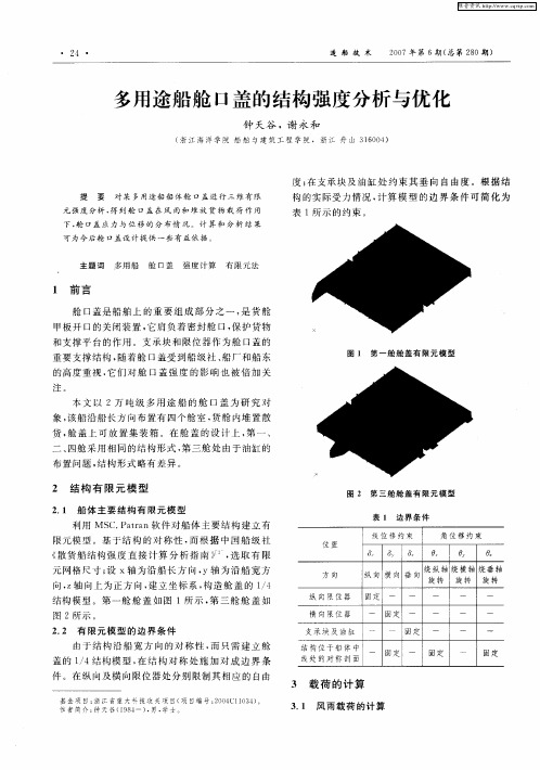
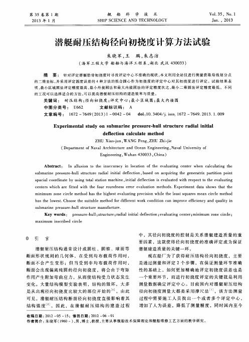
多用途船舱口盖的结构强度分析与优化
3 2 集装箱 载荷 的计算 .
对 于船 长超 过 1 0 的船 舶 , 一 舱 舱 盖 风 雨 0m 第
由于 本 次计算 关 注 的部 位 在 支承块 和 限位器 ,
故对舱 盖箱脚 下 的结 构进 行 简 化 建模 , 主要 考察 在 集 装箱 载荷作 用下 支承块 和 限位器 的受力大 小 。将 集装箱在 箱脚 处 的作用力 看作 是集 中载荷 。
度 ; 支承块 及 油缸处 约 束 其垂 向 自由度 。根 据结 在
提 要 对 某 多用 途船 船 体 舱 口盖 进 行 三 维 有 限
元 强度 分析 , 到 舱 口盖 在 风 雨 和 堆 放 货 物 栽 荷 作 用 得
构 的实 际受力 情况 , 算模 型 的边 界 条 件可 简 化 为 计 表 1 示 的约 束 。 所
5 .8 7
6 .8 3 8 .1 9 4 .2 7 5 .9 9
I0 L1 I2 I3 I4 T1 IC1
17 3 12 5 1 21 1 O7 9 4 4. 5 7 5.
表 3 第 三 舱 主 要构 件 应 力计 算 结 果
计算工况 构件名称 V FMi s应 力 Ot s e
( Pa) M
IO
I1 L2 I3 L4
L一 垂 线 问 长 , L 一 1 3 8 ; 一 取 1.m P P一 4 . + ( F 9 1 L一 1 0 “ 本 船 属 于 tp 0), y eB
重要 支撑结构 , 随着 舱 口盖受到船 级社 、 船厂 和船东 的高 度重视 , 它们对 舱 口盖强 度 的影 响也 被倍 加 关
注。
图 1 第 一舱 舱 盖 有 限 元 模 型
本 文 以 2万 吨 级 多用 途 船 的舱 口盖 为 研 究 对
应用Ansys的DDAM方法进行舰船设备的抗冲击计算

应用Ansys的DDAM方法进行舰船设备的抗冲击计算随着船舶结构和设备越来越复杂,为了提高船舶设备的抗冲击性能和确保人员的生命安全和设备运行安全,越来越多的船舶设计公司采用了基于有限元分析的抗冲击计算方法。
其中,DDAM(Dynamic Design Analysis Method)方法是一种常用的方法。
DDAM方法是一种用于评估船舶结构和设备在碰撞、爆炸等外力作用下的响应的有限元分析方法。
该方法通过给予结构和设备一定的初始速度(即冲击力),并分析其在时间和空间上的响应,以评估其抗冲击能力。
在进行DDAM计算时,需要先建立船舶结构和设备的有限元模型,并确定其材料属性和边界条件。
然后,根据需要设置冲击力的大小和作用方向,并进行动力响应分析。
最后,可以通过对响应结果的分析和判断,评估船舶结构和设备的耐冲击能力,并进行相关的优化设计。
使用Ansys软件进行DDAM计算时,可以通过建立一个完整的船舶模型以及设备模型,对其进行载荷应用和动力分析。
Ansys提供了丰富的材料库和边界条件的设置,使得用户可以针对不同的应用场景进行模拟和分析。
同时,Ansys还提供了强大的后处理功能,可对计算结果进行可视化展示和数据处理,以便进一步优化设计。
综上所述,DDAM方法是一种常用的船舶设备抗冲击计算方法,可通过动力响应分析对结构和设备的抗冲击能力进行评估和优化设计。
使用Ansys工具进行DDAM计算时,可以根据实际情况进行模拟,获得准确的计算结果,为船舶设计和制造提供技术支持。
船舶设计和制造涉及到各种参数和数据,包括船舶结构、设备规格、材料属性、载荷条件等。
这些数据对于确定船舶的性能和安全性都起到重要的作用。
以下是一些与船舶设计和制造相关的数据及其分析。
1. 船舶结构:包括船体尺寸、水线长、排水量、吃水、船坞容积等。
这些数据决定了船舶的基本性能,如稳定性、载重量、速度等。
船舶制造公司需要合理地确定这些参数来满足客户需求并达到设计要求。
潜艇耐压结构径向初挠度计算方法试验
c e n t e r s wh i c h a r e f i t t e d wi t h t he f o u r r o u n d ne s s e r r o r e v a l u a t i o n me t h o d s .Ex p e r i me n t d a t a s h o ws t h a t t h e
ha s t h e l o we s t . Ch o o s e t h e s u i t a b l e me t h o d f o r d i fe r e nt wo r k c o n d i t i o n c a n i mp r o v e e ic f i e n c y a n d q u a l i t y i n
摘 要 : 针对评定潜艇肋骨初挠度时寻找评定 中心不准确 的现状 , 本文利用全站仪进行测量获取母线 划分点
的 二维 坐标 , 并 采 用 评 定 圆度 误 差 的 4种 方 法 的 拟 合 圆心 作 为 初 挠 度 的评 定 中心 对 其 初 挠 度 进 行 评 定 。试 验 结 果 表 明, 最 小 区域 圆法 评 定 精 度 最 高 , 最 小外 接 圆 法 和 最 大 内接 圆法 的 评 定 精 度 次 之 , 最 小 二 乘 圆 法 评 定 精 度 最 低 。不 同 的工况可以选择适合的方法 , 可 以提 高 潜 艇 耐 压 结 构 的建 造 效 率 与 质量 。
不确定动态船队规划的数学模型研究
第3卷 第2 1 期
20 0 8年 6月.
中 国 航
海
V0 . 1 1 3 NO .2
N AV I AT I N F H I A G O O C N
J n.2 0 u 08
文章 编号 : 0 0 6 3 2 0 ) 2 0 5 — 0 1 0 —4 5 ( 0 8 0 — 1 8 4
机 参 数 的机 会 约 束 数 学 模 型 并进 一 步转 化 为 它 的 清 晰 等 价 类 再 进 行 船 队规 划求 解 , 其 数 学 模 型符 合 航 运 市 场 的 使
特 点 , 航运 企业 投 资 决 定 水路 运 输 ; 队 规 划 ; 学模 型 ; 确 定 性 参 数 ; 会 约 束 船 数 不 机
The he mod s tan f r e nt t lare v l n e f r t o uton offe tp a ni nt eli r s o m d i o isce quia e c o hes l i l e l n ng. Thi a h mod s b e sm t eli as d
∑
.
l
on t e ur sofs i pi a ke ,S tc da c ort hi i g i e t e . hef at e h p ng m r t O i an be agui n e f he s pp n nv s m nt K e r s:w a e w a da p t ton;m ulisa le l n ng;m a he a i o l y wo d t r y t ns ora i ; t tge fe t p a ni — t m tc m de ;un e t i y pa a et ; c nc c r ant r m er ha e
基于概率的油船破损和剩余强度预报
总第208期2020年第8期机械管理开发MECHANICAL MANAGEMENT AND DEVELOPMENTTotal 208N〇.8, 2020设计理论与方法D01:10.16525/l4-1134/th.2020.08.005基于概率的油船破损和剩余强度预报万乐天(中国船舶重工集团有限公司第七一〇研究所,湖北宜昌443003)摘要:油船搁浅或碰撞时,由于破损程度及位置是偶然的,所以利用概率的方法进行强度评估更加客观。
因此,基于协调共同规范,对某型油船破损强度进行了分析及预报,结果表明,非线性有限元结果与该型预报公式计算结果相差很小,本文预报方法快速准确。
关键词:共同规范概率剩余强度预报中图分类号:U663.2 文献标识码:A文章编号:1003-773X(2020)08-0011-02引言油船破损的位置和程度存在一定的不确定性和 随机性,由对结构破坏的程度和分布情况概率统计 分析工作的展望,船舶航行途中,通过相关事故的记 录和统计学分析,可以初步预估船体外部结构可能 发生的破损状态,对于液化石油气、危化品运输经济 性和安全性有重要意义[1]。
1计算破损概率1.1碰撞1.2搁浅纵向破损概率:/v=i--Pw-Pjia•(5)横向破损概率:P m=l-(6)垂向区域破损概率:P B V=1"_P缶.(7)式中分别为破损区域位于f后及f前部由MARPOL国际公约相关规定纵向破损概率:Psi=1■(1)垂向破损概率:(2)横向区域破损概率:Pst=^~Psi■(3)式中:足、易分别为损伤区域最后及最前一点离船艉概率;/V凡、八分别为破损区域位于油舱左、右及 下部的概率。
令最低点与底板垂向距离为破损高度为f t,则当}矣0.1,^->0.1,时,参数取值为:Ds L)sPfc=(14.5 导)+Us UsP&=0.78+1.1(-^--0.1)Ds(8)距离;、八分别为破损区域位于f后及f前部概率,L为船长;分别为破损区域位于油舱下、上及外部的概率M。
基于注意力机制的TCN-BiLSTM船舶轨迹预测
:/= 系 统 & 即 船 舶 自 动 识 别 系 统 & 是 以 国 际 海 事 组 织 为 首的多个国际组织共同规定的一个具有船舶自动识别*通 信和导航 功 能 的 新 型 助 行 电 子 系 统'&$(%:/= 系 统 由 岸 基* 星基接收设备和 船 载 设 备 共 同 组 成&安 装 了 :/= 设 备 的 船 舶可向他船及基站自动播发本船的航行信息&从而让船员 了解附近海域的海上交通情况&为船员在航行规划*监督 预警*维护安全等方面提供安全保障%
!
投 稿 网 址 BBB!0V01MT3W!1FO
第&期
郭逸婕&等)基于注意力机制的 8>I5<4J=8^ 船舶轨迹预测
#!%& #
""""""""""""""""""""""""""""""""""""""""""""""""""""
型的方法*基于概率统计的方法和基于深度学习的方法%
位置&预测 精 度 有 所 提 高%因 此&近 年 来 利 用 其 他 网 络 与
>'8:"(2+)6QE0C16FQT7QCR4164F2$8>I$J=8^$E66C264F2 OE1SE24VO$:/=
结构方程模型第二讲
特别, 1)取 W = SS, : Kronecker 乘积,则WLS 估计化为GLS; 2)取 W = (qML)(qML),则WLS 估计化为ML; 一般,Browne(1982,1984)建议W取 wgh,ij = mghij –sghsij 其中wghij是4阶样本中心矩。这是一种渐近与 分布无关的估计(asymptotically distribution-free, ADF),具有许多与ML估计相同的渐近性质。
ˆ q ) N (0, ) n(q (n )
5) ML估计的最优拟合值渐近卡方分布,即
2 ˆ (n 1)F (q ML ) ( p * t )
(n )
其中p*=p(p+1)/2,t为自由参数的个数。 这个结果可以用于整个模型的检验。 H0: (q)。
证明可参看(Bollen, 1989)
2 1/ 2
其中df 是卡方的自由度。 2-df 称为离中参数(Noncentrality parameter,NCP; Steiger, 1980)。 总体差距函数(Population Discrepancy Function, PDF):
PDF max[( df ) /(n 1),0]
STRUCTURAL EQUATION MODELING
PAGE26
Conditions when you might consider using PLS
Do you work with theoretical models that involve latent constructs? Do you have multicollinearity problems with variables that tap into the same issues? Do you want to account for measurement error? Do you have non-normal data?
15万吨散货船的屈曲强度校核
哈尔滨工程大学本科生毕业论文第1章绪论1.1 课题研究的背景、目的和必要性随着世界经济的发展,散货船运输在经济发展中的作用日益重要。
散货船载重量普遍较大,设计和建造相对简单、运输能力较强,在二十世纪七、八十年代散货船队的发展非常迅猛,以至于目前散货船的海上货物运输总量占世界商船运输总量的30%,在世界海运市场上起着非常重要的作用,扮演着举足轻重的角色。
但是,由于散货船的装载以及受力特点导致其船舶结构比其他类型船舶更容易疲劳老化,事故概率比较大;特别是老龄船,最近几年出现的海运事故呈快速上升趋势。
1980年至1995年期间,143艘2万载重吨以上的散货船发生严重的海损事故,其中72艘沉没,导致916人死亡。
因此,散货船安全引起了国际海事组织的高度重视;同时也引起了老龄船船东和经营管理者的重视[1]。
由于散货船市场上有5000艘船舶面临船龄老化,近几年将迎来运力拆解的高峰,这对于新造散货船市场极为利好[2]。
其中,安全性是船舶制造的重中之重。
为保证船体结构的安全性,需考虑船体结构在极端载荷作用下其强度问题满足要求。
对整个船体进行有限元分析,同时考虑几何和材料非线性,无疑可以得到船体的极限强度值,但这需要花费大量的人力资源、资金和计算时间。
因此有必要开发计算船体结构总纵极限强度的简化方法。
世界各国船级社都有各自的相关规范,中国船级社(CCS)给出了《散货船结构强度直接计算分析指南》[3],该指南给出了计算散货船结构强度的简便方法。
因此,本文主要全面理解和掌握CCS《散货船结构强度直接计算分析指南》的编写理念和要求,在此基础上,以一条15万吨散货船“港明轮”为例,按照CCS直接计算分析指南的要求建立三舱段有限元模型,进行船体结构强度直接计算,通过对该实船三舱段有限元模型的屈曲强度分析,对其所涉及的原理进行深入的研究,并分析计算六种不同工况以及各工况下船体构件的1哈尔滨工程大学本科生毕业论文2失稳特点。
同时,国际船级社协会(IACS)一直在致力于散货船和油船共同结构规范的制定与实施工作。
- 1、下载文档前请自行甄别文档内容的完整性,平台不提供额外的编辑、内容补充、找答案等附加服务。
- 2、"仅部分预览"的文档,不可在线预览部分如存在完整性等问题,可反馈申请退款(可完整预览的文档不适用该条件!)。
- 3、如文档侵犯您的权益,请联系客服反馈,我们会尽快为您处理(人工客服工作时间:9:00-18:30)。
Computational Crack Path Prediction for Ship Structural Details
Y. Sumi Department of Systems Design for Ocean-Space, Yokohama National University 79-5 Tokiwadai, Hodogaya-ku, Yokohama 240-8501, Japan sumi@structlab.shp.ynu.ac.jp
ABSTRACT. The characteristics of fatigue crack propagation and the remaining life assessment of ship structures are investigated focusing attention on a curved crack path due to the effects of weld, complicated stress distributions at three-dimensional structural joints, and structural redundancy. An advanced numerical simulation method is demonstrated for the remaining life assessment of curved crack propagation. The simulation method is based on a step-by-step finite element analysis. The crack path is predicted by the perturbation method with the local symmetry criterion, which gives a higher order approximation of the crack path, while the finite element re-zoning is carried out by an improved paving method. Fatigue crack paths in the welded structural details of the transverse girder of a ship structure are investigated so that one can find the detailed design, which prevents the break of the plates forming a compartment boundary. It is found that the present method may offer an efficient simulation-based tool for the design of critical details.
INTRODUCTION The fitness for serviceability of structural members of ships is of great interest for the prevention of instantaneous failures as well as the loss of serviceability such as oil and/or water tightness of critical compartments [1]. The characteristics of fatigue crack propagation and the remaining life assessment of ship structures have been investigated focusing attention on a curved crack path due to the effects of weld, complicated stress distributions at three-dimensional structural joints, and structural redundancy [2, 3, 4] . In the present paper, an advanced numerical simulation system is proposed for the remaining life assessment of curved crack propagation. The simulation method is based on a step-by-step finite element analysis. Crack paths are predicted by the perturbation method applying the local symmetry criterion, which gives a higher order (curved) approximation of an each incremental crack extension. The finite element re-zoning is carried out by an improved paving method, which provides a very robust mesh generation by quadrilateral finite elements during the entire crack growth process without user intervention. Fatigue crack paths are investigated for welded structural details of a transverse girder of a ship structure, and their crack propagation lives are estimated to prevent the break of the shell plate during the ship operation. The influencing factors such as geometry of structural details, welding residual stress, structural redundancy, as well as crack paths are taken into consideration in the simulation, so that realistic phenomena of fatigue crack propagation can be obtained. It is found that the present method may offer an efficient simulation-based tool for the design of critical details where retarded cracks can be visually detected by the regular inspection.
AN ADVANCED SIMULATION SYSTEM FOR THE ASSESSEMENT OF REMAINING LIVES AND PATHS OF FATIGUE CRACKS
Simulation System In this section discussions are made for a simulation system, which may give an accurate assessment of both the crack propagation life and the final failure mode of a welded ship structure. A step-by step finite element approach, which was originally developed for brittle crack paths, has been extended to fatigue crack path prediction [2, 3, 4], in which an accurate stress intensity analysis, a proper crack path criterion, an accurate growth rate equation, and an automatic mesh generation algorithm are required. A fatigue crack is modeled as a two-dimensional crack in a plate, and the simulation consists of the following steps; 1. Prepocessing: finite element mesh is automatically generated by an advanced paving method [5,6], and the super-element is also defined for structural elements outside the crack propagating zone, 2. Crack analysis: stress field parameters near a crack tip are calculated by the method of superposition of analytical and finite element solutions [7,8], 3. Crack path prediction: curved crack extension is predicted by the first order pertur-bation method with the use of local symmetry criterion [9,10,11], 4. Crack growth calculation: crack growth is calculated by the Paris’ law , 5. Back to step 1 to continue simulation. In each step a cracked domain is subdivided into new finite element mesh by an advanced paving method, which is specially developed for the refined smooth mesh gradation for crack analysis in the present work. The stress field parameters of the Irwin-Williams’ expansion are determined by the method of superposition of analytical and finite element solutions [7,8], where not only the stress intensity factors but also the T-stress and higher order coefficients are determined for an accurate prediction of a curved crack path. The crack tip is then moved to a certain point on the predicted path, which is obtained analytically by the first order perturbation method [9,10] with the local symmetry criterion [11]. The crack growth life is evaluated by the stress intensity range along the curved crack path, and the procedure will be repeated until the final stage of the crack propagation is reached. A GUI-system has been developed so that user-friendly environment is established for the input and output phases of the simulation.