光照传感器使用说明
光照度传感器的使用方法
光照度传感器的使用方法嘿,咱今儿就来说说这光照度传感器的使用方法!你可别小瞧了这玩意儿,它就像是我们的小眼睛,能敏锐地感知周围光线的变化呢!想象一下,这光照度传感器就像一个特别机灵的小侦探,时刻在帮我们留意着光线的情况。
要使用它呀,首先得找个合适的地方安家。
就好比你住房子得挑个舒服的地儿一样,咱得给它找个能准确检测光线的好位置。
一般来说,放在没有遮挡、能直接感受到光线的地方最好啦。
然后呢,就是要给它接上电,让它有能量干活呀!这就跟人得吃饭才有劲一个道理。
接上电后,它就开始工作啦,兢兢业业地检测着光照度。
你说这光照度传感器能干嘛呢?那用处可多了去了!比如说在智能家居里,它能根据光线的强弱自动调节灯光的亮度。
白天光线强的时候,它就告诉灯别那么亮啦,省点电;晚上光线暗了,它就赶紧让灯亮起来,多贴心啊!这不就像你有个特别懂你的小伙伴,知道你啥时候需要啥。
再比如在农业领域,它能帮农民伯伯们监测光照情况,指导他们什么时候该让农作物晒太阳,什么时候得遮遮阳,这多重要啊!就像农民伯伯的好帮手一样。
在一些工厂里,它也能发挥大作用呢。
可以用来监测工作环境的光照度是否合适,保障工人的工作效率和安全。
你想想,要是光线太暗或者太亮,工人干活能舒服吗?哎呀,说了这么多,你是不是对光照度传感器的使用方法有点感觉了?其实啊,用它就跟和朋友相处一样,你得了解它的脾气,知道怎么让它发挥最大的作用。
可别觉得它复杂,只要你用心去摆弄摆弄,很快就能上手啦!而且现在的光照度传感器越来越智能,操作也越来越简单。
就像现在的手机一样,以前觉得好复杂,现在不都人人会用嘛!总之呢,光照度传感器是个很实用的小玩意儿,只要你会用,它能给你的生活和工作带来很多便利呢!别犹豫啦,赶紧去试试吧!让它为你服务,让你的生活更加智能化、便捷化!怎么样,是不是有点心动啦?快去和这个小机灵鬼打交道吧!。
智能农业中的传感器技术使用教程

智能农业中的传感器技术使用教程随着科技的不断发展,智能农业成为农业领域的热门话题。
在智能农业中,传感器技术起着至关重要的作用。
传感器可以帮助农民实时监测农作物的生长状况、土壤湿度、气象变化等关键信息,并进行精确的农业管理。
本文将为您介绍智能农业中的传感器技术使用教程,帮助您在农业生产过程中更好地利用传感器技术,提高农业生产效率和质量。
传感器是一种用于检测和测量某种物理量的装置,它能将检测到的物理量转换为电信号或其他可识别的形式,从而提供准确的数据。
在智能农业中,常用的传感器包括土壤湿度传感器、气象传感器、光照传感器等。
接下来,我们将重点介绍这三种传感器的使用方法和注意事项。
首先是土壤湿度传感器。
土壤湿度是影响作物生长的关键因素之一。
传感器能够定时测量土壤湿度,并将数据传输至中控系统。
使用土壤湿度传感器的步骤如下:1. 安装传感器:将传感器插入土壤中,确保与根部接触良好。
2. 设置传感器:根据不同作物的需求,设置传感器的阈值。
阈值一般根据土壤湿度的百分比来设定,例如,设定80%为湿度较高的阈值。
3. 数据收集与分析:设置好传感器后,开始收集土壤湿度的数据,并进行分析。
根据数据分析结果进行相应的浇水、排水等管理工作。
其次是气象传感器。
气象传感器能够监测气温、湿度、风速等天气变化,为农民提供气象数据。
使用气象传感器的步骤如下:1. 安装传感器:将传感器安装在采集点附近的合适位置,确保没有遮挡物,能够正确地感知周围环境的气象情况。
2. 设置传感器:根据所处地区的气象特点,设置传感器的相关参数,如温度单位、湿度上限、风速报警等。
3. 数据收集与分析:传感器会定时地采集气象数据,将其传输到中控系统。
农民可以通过中控系统实时查看气象数据,并根据数据分析结果进行农业管理。
最后是光照传感器。
光照传感器可以测量光照强度和光周期,帮助农民确定合适的光照条件,促进植物的生长。
使用光照传感器的步骤如下:1. 安装传感器:将传感器安装在作物生长的区域内,确保光照传感器能够准确地感知到光照情况。
光电传感器使用说明
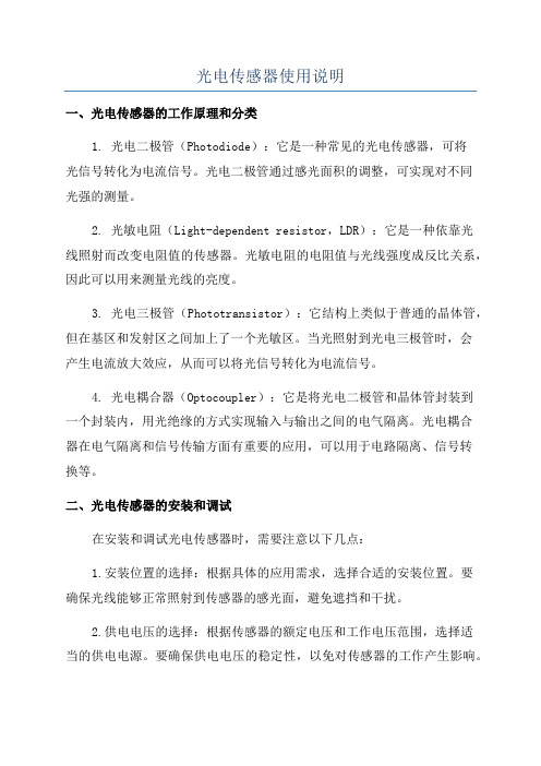
光电传感器使用说明一、光电传感器的工作原理和分类1. 光电二极管(Photodiode):它是一种常见的光电传感器,可将光信号转化为电流信号。
光电二极管通过感光面积的调整,可实现对不同光强的测量。
2. 光敏电阻(Light-dependent resistor,LDR):它是一种依靠光线照射而改变电阻值的传感器。
光敏电阻的电阻值与光线强度成反比关系,因此可以用来测量光线的亮度。
3. 光电三极管(Phototransistor):它结构上类似于普通的晶体管,但在基区和发射区之间加上了一个光敏区。
当光照射到光电三极管时,会产生电流放大效应,从而可以将光信号转化为电流信号。
4. 光电耦合器(Optocoupler):它是将光电二极管和晶体管封装到一个封装内,用光绝缘的方式实现输入与输出之间的电气隔离。
光电耦合器在电气隔离和信号传输方面有重要的应用,可以用于电路隔离、信号转换等。
二、光电传感器的安装和调试在安装和调试光电传感器时,需要注意以下几点:1.安装位置的选择:根据具体的应用需求,选择合适的安装位置。
要确保光线能够正常照射到传感器的感光面,避免遮挡和干扰。
2.供电电压的选择:根据传感器的额定电压和工作电压范围,选择适当的供电电源。
要确保供电电压的稳定性,以免对传感器的工作产生影响。
3.输出信号的接收和处理:根据传感器的输出信号类型和电平,选择合适的接收和处理电路。
可以通过模拟电路或数字电路来处理传感器的输出信号。
4.灵敏度的调节:根据具体的应用需求,调节传感器的灵敏度。
对于光电二极管和光敏电阻等传感器,可以通过调节外部电阻来实现。
三、光电传感器的应用领域1.自动控制:光电传感器可以用于自动控制系统,如照明控制、清晰度检测、颜色识别等。
通过检测环境光照的变化,实现对设备的自动控制。
2.测量仪器:光电传感器可以用于测量仪器中,如光谱仪、测量器等。
通过测量光线的强弱、波长等,实现对物理量的测量。
3.光通信:光电传感器可以用于光通信系统中,如光纤通信、光模块等。
IIOT-LR2000光照传感器说明书

光照度传感器说明书IIOT-LR2000光照传感器使用说明书V2.2目录1.产品资料 (2)2.产品概述 (2)2.1.产品特点 (2)2.2技术参数 (2)2.3光照参数 (3)2.4探头参数与选型 (4)2.5产品尺寸 (4)3.模拟量4-20mA参数含义 (5)1)当选择量程为0-65535lux时 (5)2)当选择量程为0-20WLux时 (5)4.通讯协议 (5)4.1通讯基本参数 (5)4.2数据帧格式定义 (6)4.3寄存器地址 (7)4.4通讯协议示例以及解释 (7)5.常见问题及解决办法 (8)5.1设备无法连接到电脑 (8)6.安装说明 (9)6.1设备安装前检查 (9)6.2接口说明 (10)6.3安装形式 (10)7.接线图 (10)7.1RS485型接线定义 (10)7.2模拟量型接线定义 (11)8.联系方式 (11)9.质保与售后 (12)10.免责声明 (12)11.修订记录 (12)1.产品资料产品说明书下载地址:https:///product/2048.html设备上云操作指导详情:https:///news/1204.html2.产品概述该变送器广泛适用于农业大棚、花卉培养等需要光照度监测的场合。
传感器内部的输入电源、感应探头、信号输出三部分完全隔离。
安全可靠,外观美观,安装方便。
2.1.产品特点●感光探头灵敏度高、信号稳定、精度高。
●测量范围宽、线性度好、防水性能好。
●使用方便、便于安装、传输距离远。
●高一致性,出厂全部严格标定校正。
2.2技术参数参数名称参数内容产品名称:光照度传感器产品供电:12-24V DC产品功率:<0.4W(RS485)<1.2W(模拟量)工作环境:工作湿度:0-85%RH工作温度:-25-70℃量程:0-65535Lux/0-20万Lux精度:±5%光照度长期稳定性:≤5%/y输出方式RS485接口,Modbus-RTU通讯协议4-20mA接口,电流信号模拟量负载能力电流输出,≤600欧姆尺寸规格:110×85×44mm³壁挂式王字壳IP防护等级:IP65防水防尘2.3光照参数如图1所示,不同波长光线对光照度的影响,波长在580nm左右最准确,比例系数为1。
光照度传感器

简介
光照度传感器主要用于检测光照度大小。
使用标准
光照度,可简称照度,其计量单位的名称为“勒克斯”,简称“勒”,单位符号为“Lux”。 1Lux为1个烛光在1米距离的光亮度。 夜晚室内灯光:100-200Lux 晴天室内灯光:1000-5000Lux 北方室外正午:-Lux 南方室外正午:-Lux 夜里明亮月光下: 0.3~0.03 Lux; 夜里没有月光下:0.003~0.0007 Lux;
应用
主要应用于农业大棚、温室大棚、农业大田、城市照明、仓库、工业车间等环境。
光照度传感器例如:像住宅那样整体照度应该在100勒克斯(Lux)的情况,而即使是90勒克斯(Lux)也不会对 生活带来很大的影响。但是,如果是道路照明的话,情况就不同了。假设路面照度必须在20勒克斯(Lux)的情况 下,如果是18勒克斯(Lux)的话,就有可能造成交通事故频发。商店也是一样,例如,商店的整体最佳照度是500 勒克斯(Lux),由于用600勒克斯(Lux)的照度。所以,照明灯具数量和电量就会增加,并在经济上造成影响。
光照度传感器
将光照度大小转换成电信号的传感器
01 简介
03 技术参数
目录
02 使用标准 04 应用
Hale Waihona Puke 光照度传感器是将光照度大小转换成电信号的一种传感器,输出数值计量单位为Lux。光是光合作用不可缺 少的条件;在一定的条件下,当光照强度增强后,光合作用的强度也会增强,但当光照强度超过限度后,植物叶 面的气孔会关闭,光合作用的强度就会降低。因此,使用光照度传感器控制光照度也就成为影响作物产量的重要 因素。
谢谢观看
技术参数
光照度传感器(1张)感光元件:对弱光有较高反应的感光元件 直流供电:10-30VDC; 准确度: ±7%(25℃); 湿度特性: ±3%RH(60%RH,25℃); 温度特性: ±0.5%/℃(25℃); 测量范围: 0~Lux 输出信号:4~20mA电流输出;0~5V/0~10V电压输出
光照度传感器MODBUS

四、选型:技术说明:1、照度是体现光照强弱的单位,其通俗定义为照到单位面积(m²)上的光通量。
照度单位是每平方米的流明(Lm),也被称为勒克斯(Lux)。
2、1个单位的照度大约为1个烛光在1米距离的光亮度。
在我国,一般情况下,夏日晴天强光下照度为10万Lux(3~30万Lux),阴天照度为1万Lux,日出、日落光照强度为300~400Lux,室内日光灯照度为30~200Lux,夜里0.3~0.03Lux(明亮月光下),0.003~0.0007Lux(阴暗的夜晚)一、产品概述:光照度变送器(光照度传感器)是采用具有较高灵敏度的感光探测器,配合高精度线性放大电路,经过严密检测、生产的具有多种光照测量范围和信号输出类型的实用型产品。
变送器外壳采用壁挂安装设计,结构精致、外型美观,是一款应用范围广泛、性价比极高的光照度测量产品。
五、接线图:三、外形尺寸:RS485(RS232)型接线:供电:红线(V+)黑线(V-)通信:黄线(A+/TXD)蓝线(B-/RXD)电压输出:0-5V 和0-10V 供电:红线(V+)黑线(V-)输出:黄线二线制电流输出接线图V+:红线V-:黑线六、通信说明:(只针对于RS232RS485和无线输出型)典型推荐:室内测量量程0~20000Lux ,室外或温室测量量程:0~20万Lux本产品采用标准Modbus-RTU 通讯协议,产品出厂默认地址为1,波特率为9600,8位数据位,无奇偶校验,1位停止位0~20000Lux光照度上传的数据为真实值0~20万Lux 光照度上传的数据需乘以10才为真实值(采集得到的数据为0~20000)6.1查询地址为1的仪表的光照度值(读输入寄存器)6.2查询地址为1的仪表读保存寄存器6.3写入单个保存寄存器,读从机输入寄存器(4X 类型)中的二进制数据,寄存器所对应的地址分别为0-136.4写入把地址波特率修改为4800(4800的16进制为12C0)七、注意事项:1、使用前请认真阅读说明书、确保接线正确:任何错误接线均有可能对变送器造成不可逆伤害。
光照传感器说明书VI
北京腾控智仪科技有限公司
光照强度传感器使用说明书
测量参数
光照范围: 1~200Klux
测量精度:±5%
光谱范围:400~1100nm(敏感区域集中在植物生长所需自然光谱内)
反应时间: < 2S
信号类型:0~2V / 4~20mA
转换公式:光照= V/0.01 (Klux)
光照= (I-4)*200/16 (Klux)
电路参数
工作电压:11~24V(典型值12V)
静态功耗:约 8mA
工作温度范围:-35℃~75℃
输出负载:< 300Ω(典型值100Ω)
功能特点
体型小巧,安装方便
壳体密封性好,防水
测量精度较高,稳定性好
采用300~800nm视觉修正光学片
50%以上感光区域集中在400~800nm范围,适合植物所需自然光的照度测量
引线定义
电源正:红色线电源地(信号地):黑色线信号正:绿色线
注意事项
本传感器对自然光源及热光源较敏感,对冷光源不敏感,所以不适合荧光测量。
采光球罩为玻璃材质,请勿磕碰,摔打,须轻拿轻放。
内部已固定,请勿私自拆卸外壳,以免位置发生变动影响测量。
传感器如果长期放置在室外,球罩应定期擦拭,以免影响透光。
当光照较强时输出电流随之增大,可能会对内部电路升温,建议采用间歇供电。
适用范围
可广泛用环境、温室、实验室、养殖、建筑、高档楼宇、工业厂房等的光线强度测量。
APDS-9002 微型表面接盘光照传感器数据手册说明书
APDS-9002Miniature Surface-Mount Ambient Light Photo SensorData SheetDescriptionThe APDS-9002 is a low-cost analog-output ambient light photo sensor in lowest cost miniature chipLED lead-free surface mount package. It consists of a spectrally suited phototransistor, which peaks in human luminosity curve. Hence, it provides an excellent responsivity that is close to the response of human eyes, as shown in Figure 2. It provides a design-alternative to the HSDL-9000 digital-output ambient light photo sensor is suitable for portable applications with its ultra small package design.The APDS-9002 is ideal for applications in which the measurement of ambient light is used to control display backlighting. Mobile appliances such as the mobile phones and PDAs that draw heavy current from display backlighting will benefi t from incorporating these photo sensor products in their designs by reducing power con-sumption signifi cantly.Features∙ Excellent responsivity which peaks in the human luminosity curve– Close responsivity to the human eye∙ Miniature chipLED lead-free surface-mount package – Height – 0.80 mm– Width – 2.00 mm– Depth – 1.25 mm∙ Good output linearity across wide illumination range∙ Low sensitivity variation across various light sources∙ Guaranteed temperature performance: -40° C to 85° C∙ VCC supply 2.4 to 5.5 V∙ L ead-free packageApplications∙ Detection of ambient light to control display back-lighting– Mobile devices – mobile phones, PDAs– Computing devices – notebooks, webpads– Consumer devices – TVs, video cameras, digital still cameras∙ Automatic residential and commercial lighting management∙ Electronic signs and signals∙ Daylight and artifi cial light exposed devicesI/O Pins Confi guration TablePin Symbol Description1IOUTI OUT 2 VCC V CC 3 VCC V CC4 NCNo ConnectApplication Support InformationThe Application Engineering Group is available to assist you with the application design associated with APDS-9002 ambient light photo sensor module. You can contact them through your local sales representatives for additional details.Ordering InformationPart NumberPackaging TypePackageQuantityAPDS-9002-021Tape and Reel4-pins Chipled package2500Typical Application CircuitFigure 1 TableComponentRecommended Application Circuit ComponentsR LOAD1 kFigure 1. Typical application circuit for APDS-9002.CAUTION: It is advised that normal static precautions be taken in handling and assemblyof this component to prevent damage and/or degradation which may be induced by ESD.N O R M A L I Z E D R E S P O N S I V I T Y0WAVELENGTH (nm)0.50.10.41.11.00.70.20.30.60.90.8Figure 2. Relative spectral response vs. wavelength.Absolute Maximum RatingsFor implementations where case to ambient thermal resistance is ≤ 50°C/WParameter Symbol Min. Max. UnitsStorage Temperature T S -40 85 °C Operating Temperature T A -4085 °C Supply VoltageV CC2.4 5.5 V Recommended Operating ConditionsParameter Symbol Min. Max. Units ConditionsOperating Temperature T A -40 85 °C Supply VoltageV CC2.4 5.5 VElectrical & Optical Specifi cations (T A = 25° C)Parameter Symbol Min. Typ. Max. Units ConditionsPhoto Current (I) I_PH1 10 20 33 μA V CC = 3.0 V, Lux = 10[2]Photo Current (II) I_PH2136 250 410 μAV CC = 3.0 V, Lux = 100[2]Photo Current (III) I_PH3 –300 – μAV CC = 3.0 V, Lux = 100[1]Dark Current I_DARK – 50 160 nA V CC = 3.0 V, Lux = 0Light Current Ratio I_PH3 / I_PH2– 1.2 – – –Rise Time T_RISE – 0.95 2 ms V CC = 3.0 V, Lux = 100, Rload = 1 k Ω[3]Fall TimeT_FALL – 0.8 2 ms V CC = 3.0 V, Lux = 100, R load = 1 k Ω[3]Notes:1. Illuminance by CIE standard light source (incandescent lamp).2. Fluorescent light is used as light source. White LED is substituted in mass production.3. White LED is used as light source.Light Measurement Circuit and WaveformsLOADI_pulseGNDPIN 2: VCCPIN 3: VCCFigure 3. Photocurrent vs. luminence (V CC = 3 V, T A = 25° C).Figure 4. Normalized photocurrent vs. temperature (V CC = 3 V, 100 LUX).Figure 5. Normalized photocurrent vs. angle (V CC = 3 V, T A = 25° C).Figure 6. Output voltage vs. luminance at diff erent load resistor.Figure 7. Fall time vs. R LOAD .Figure 8. Rise time vs. R LOAD .LUXP H O T O C U R R E N T (A )0.010.0010.00010.00001TEMPERATURE (C)N O R M A L I Z E D P HO T O CUR R E N TANGLEN O R M A L I Z E D P H O T O C U R R E N T1.21.000.20.40.60.8LUMINANCE, Ev (LUX)O U T P U T V O L T A G E , V O U T (V )1010.010.0010.1R LOAD (:)F A L L T I M E (s e c )000.0E+0200.0E-6400.0E-6600.0E-6800.0E-61.0E-31.2E-31.4E-3R LOAD (:)T r i s e (s e c )000.0E+0200.0E-6400.0E-6600.0E-6800.0E-61.0E-31.2E-31.6E-31.4E-31.8E-3MATERIAL OF COVER TAPE: PVCMETHOD OF COVER: HEAT SENSITIVE ADHESIVEUNIT: mm"B""C"17875± 0.50DETAIL A±Baking ConditionsIf the parts are not stored in dry conditions, they must be baked before refl ow to prevent damage to the parts.Package Temp. TimeIn Reels 60° C 20 hours In Bulk125° C5 hoursMoisture Proof PackagingAll APDS-9002 options are shipped in moisture proof package. Once opened, moisture absorption begins. This part is compliant to JEDEC Level 4.Recommended Refl ow Profi let-TIME (SECONDS)T – T E M P E R A T U R E – (°C )23020016012080180220255P1HEAT UPP2SOLDER PASTE DRY P3SOLDERREFLOWP4COOL DOWN25Process ZoneSymbol∆T Maximum ∆T/∆TimeHeat Up P1, R1 25° C to 160° C 4°C/s Solder Paste Dry P2, R2 160° C to 200° C0.5°C/s Solder Refl ow P3, R3 200° C to 255° C (260° C at 10 seconds max.) 4°C/s P3, R4 255° C to 200° C -6°C/s Cool DownP4, R5200° C to 25° C-6°C/sThe refl ow profi le is a straightline representation of a nominal temperature profi le for a convective refl ow solder process. The temperature profi le is divided into four process zones, each with diff erent ∆T/∆time temperature change rates. The ∆T/∆time rates are detailed in the above table. The temperatures are measured at the component to printed circuit board connections.In process zone P1, the PC board and APDS-9002 castella-tion pins are heated to a temperature of 160° C to activate the fl ux in the solder paste. The temperature ramp up rate, R1, is limited to 4° C per second to allow for even heating of both the PC board and APDS-9002 castellations.Process zone P2 should be of suffi cient time duration (60 to120 seconds) to dry the solder paste. The temperature is raised to a level just below the liquidus point of the solder, usually 200° C (392° F).Process zone P3 is the solder refl ow zone. In zone P3, thetemperature is quickly raised above the liquidus point of solder to 255° C (491° F) for optimum results. The dwell time above the liquidus point of solder should be between 20 and 60 seconds. It usually takes about 20 seconds to assure proper coalescing of the solder balls into liquid solder and the formation of good solder connections. Beyond a dwell time of 60 seconds, the intermetallic growth within the solder connections becomes excessive, resulting in the formation of weak and unreliable connec-tions. The temperature is then rapidly reduced to a point below the solidus temperature of the solder, usually 200° C (392° F), to allow the solder within the connections to freeze solid.Process zone P4 is the cool down after solder freeze. Thecool down rate, R5, from the liquidus point of the solder to 25° C (77° F) should not exceed 6° C per second maximum. This limitation is necessary to allow the PC board and APDS-9002 castellations to change dimensions evenly, putting minimal stresses on the APDS-9002.Appendix A: SMT Assembly Application NoteAvago APDS-9002: Miniature Surface-Mount Ambient Light SensorFigure 9. Stencil and PCBA.1.1 Recommended Land Pattern0.45SOLDER MASKFigure 10. Solder stencil aperture.Figure 11. Adjacent land keepout and solder mask areas.1.2 Recommended Metal Solder Stencil ApertureIt is recommended that a 0.10 mm (0.004 inches) thick stencil be used for solder paste printing. Aperture opening for shield pad is 0.6 mm x 0.6 mm. This is to ensure adequate printed solder paste volume and no shorting.1.3 Adjacent Land Keepout and Solder Mask AreasAdjacent land keep-out is the maximum space occupied by the unit relative to the land pattern. There should be no other SMD components within this area.The minimum solder resist strip width required to avoid solder bridging adjacent pads is 0.2 mm.Note: Wet/L iquid Photo-Imageable solder resist/mask is recommended.Appendix B: Optical Window Design for APDS-90022.0 Optical Window DimensionsTo ensure that the performance of the APDS-9002 will not be aff ected by improper window design, there are some constraints on the dimensions and design of the window. There is a constraint on the minimum size of the window, which is placed in front of the photo light sensor, so that it will not aff ect the angular response of the APDS-9002. This minimum dimension that is recommended will ensure at least a ±35° light reception cone.If a smaller window is required, a light pipe or light guide can be used. A light pipe or light guide is a cylindricalpiece of transparent plastic, which makes use of total internal refl ection to focus the light. The thickness of the window should be kept as minimum as possible because there is a loss of power in every optical window of about 8% due to refl ection (4% on each side) and an additional loss of energy in the plastic material.Figures 12(a) and 12(b) illustrate the two types of windows that we have recommended which could either be a fl at window or a fl at window with light guide.Figure 12(a). Window size determination for fl at window.Figure 12(b). Window design of flat window with light guide.FLATPHOTO LIGHT SENSORPHOTO LIGHT SENSORZTOP VIEWD1WINDOW DIAMETER T THICKNESSL LENGTH OF LIGHT PIPEZDISTANCE BETWEEN WINDOW REAR PANEL AND APDS-9002Table 1 and Figure 13 below show the recommended dimensions of the window. These dimension values are based on a window thickness of 1.0 mm with a refractive index 1.585.The window should be placed directly on top of the photo light sensor to achieve better performance and if a fl at window with a light pipe is used, dimension D2 should be 1.5 mm to optimize the performance of APDS-9002.2.1 Optical Window MaterialThe material of the window is recommended to be poly-carbonate. The surface fi nish of the plastic should be smooth, without any texture.The recommended plastic material for use as a window is available from Bayer AG and Bayer Antwerp N. V. (Europe), Bayer Corp. (USA) and Bayer Polymers Co., Ltd. (Thailand), as shown in Table 2.Table 1. Recommended Dimension for Optical WindowAll dimensions are in mmWD (T+L+Z)Flat Window (L = 0.0)Flat Window with Light Pipe (D2 = 1.5; Z = 0.5)ZD1D1L1.50.52.25––2.0 1.0 3.25––2.5 1.5 4.25––3.0 2.0 5.00 2.5 1.5Table 2. Recommended Plastic MaterialsMaterial NumberVisible Light TransmissionRefractive IndexMakrolon LQ264787% 1.587Makrolon LQ3147 87% 1.587Makrolon LQ318785%1.587Figure 13. Recommended window dimensions.Appendix C: General Application Guide for APDS-9002The APDS-9002 is a low cost analog-output ambient light photo sensor which spectral response closely emulates the human eyes. APDS-9002 consists of a phototransis-tor that enables the photo sensor to produce a high gain photo current to a suffi cient level that can be converted to voltage with a standard value of external resistor. APDS-9002 is then easily integrated into systems that use ADC input which is available for sampling of the external source, as shown in Figure 14 below.Selection of the load resistor R L will determine the amount of current-to-voltage conversion in the circuit. Based on Figure 14 and using white LED as the light source, mea-surement has been carried out by using diff erent load resistors to examine the variation of the output voltage towards the intense of LUX. The result is shown in Graph 1. APDS-9002 allows output voltage hits around 2.3 V, after this it saturates.L ight source, e.g., fl uorescent light, consists of ac noise about 100 Hz frequency. A capacitor of 10 F, which acts as a low-pass fi lter, is recommended to add in parallel with resistor to by-pass the ripples.The amount of converted voltage, V OUT, is mainly dependant proportionally on the photo current which is generated by the brightness of the light shone on the photo sensor and the load resistor used, R L. Increasing the brightness of the light and/or the load resistor will increase the output voltage.Brightness is measured as “LUX” unit, which describes how intense a light source that our eyes perceive. LUX meter is the equipment for “LUX” measurement. Light sources with the same LUX level appear at the same brightness to the human eyes.LUMINANCE, Ev (LUX)OUTPUTVOLTAGE,VOUT(V)1010.010.0010.1V VLIGHTSOURCEGraph 1. Output voltage vs. luminance at diff erent load resistor. Figure 14. Confi guration of APDS-9002 being used directly.Figure 15. Evaluation board layout.For product information and a complete list of distributors, please go to our web site: Avago, Avago Technologies, and the A logo are trademarks of Avago Technologies in the United States and other countries.Data subject to change. Copyright © 2005-2012 Avago Technologies. All rights reserved. Obsoletes 5989-3051EN AV02-3579EN - June 11, 2012Avago has fabricated an evaluation board based on the confi guration shown in Figure 14 for the designer to test the ambient light sensor under diff erent lighting condi-tions. A reference layout of a 2-layout Avago evaluation board for APDS- 9002 is shown in Figure 15 below.Mouser ElectronicsAuthorized DistributorClick to View Pricing, Inventory, Delivery & Lifecycle Information:A vago Technologies:APDS-9002-021。
模拟量型光照度传感器使用说明书
模拟量型光照度传感器使用说明书目录目录第1章产品简介 (3)1.1产品概述 (3)1.2功能特点 (3)1.3主要参数 (3)1.4探头参数与选型 (6)第2章硬件连接 (8)2.1设备安装前检查 (8)2.2接口说明 (8)2.3安装说明 (9)第3章接线说明 (9)3.1典型四线制接线方式 (9)3.2典型三线制接线方式 (11)第4章模拟量参数含义 (13)4.1模拟量4-20mA电流输出 (13)4.2模拟量0-10V电压输出 (13)4.3模拟量0-5V电压输出 (14)第5章包装售后 (15)5.1产品附加说明书 (15)5.2产品包装清单 (15)5.3联系方式 (15)5.4质保与售后 (16)5.5免责声明 (16)第1章产品简介1.1产品概述该变送器广泛适用于农业大棚、花卉培养等需要光照度及温湿度监测的场合。
传感器内输入电源,感应探头,信号输出三部分完全隔离。
安全可靠,外观美观,安装方便。
采用模拟量形式输出,方式灵活,可以输出电流型或者电压型,接线可以采用三线制或者四线制。
1.2功能特点本产品采用高灵敏度的感光探头,信号稳定,精度高。
具有测量范围宽、线形度好、防水性能好、使用方便、便于安装、传输距离远等特点。
1.3主要参数1.3.1基本参数光照强度量程0-65535Lux/0-20万Lux最大功耗光照强度精度±7%(25℃)供电电源12V-24VDC工作温度-25℃-85℃工作湿度0%RH-80%RH长期稳定性≤5%/y响应时间0.1s外形尺寸110×85×44mm3电流输出类型4mA-20mA电流输出负载≤600欧姆电压输出类型0-5V/0-10V电压输出负载≤250欧姆<1.15W工作压力范围0.9-1.1atm1.3.2光照参数图1不同波长光线对光照度影响如图1所示,波长在580nm左右最准确,比例系数为1。
模拟量型光照度传感器使用说明书传感器图2光照角度影响示意图如图2所示角度对光照准确度影响较大,用户使用时应注意角度的变化。
光照传感器流程
光照传感器流程
1. 光信号接收:
光源(如自然光、灯光)发出光线,照射到光照传感器的感光元件上。
在汽车江湖应用中,可能是用于自动大灯开启系统,而在其他领域则可能涉及农业温室控制、建筑智能照明等。
2. 光电转换:
光照传感器中的光敏元件,如光敏电阻、光电池或光电二极管等,将接收到的光强度转化为电信号。
光强越大,产生的电信号越强;反之,光弱时电信号较弱。
3. 信号处理:
传感器将得到的微弱电信号进行放大和滤波处理,以便消除噪声并提高信噪比。
在某些高级传感器中,信号还会经过模数转换器(ADC),把模拟信号转换为数字信号,便于进一步处理和传输。
4. 数据处理与决策:
微处理器或控制器接收经处理后的数字信号,并基于预设阈值或算法进行判断和运算。
汽车江湖中,当光照低于一定阈值时,控制系统会根据这些信
息触发车辆自动开启前照灯;在智能家居或智能建筑中,可能会据此调整室内照明亮度。
5. 执行动作:
根据处理结果,相关设备采取相应行动。
例如,在满足条件时,驱动执行机构(如继电器、马达或电子开关)打开或关闭照明设备,或者调节照明强度。
6. 数据记录与监控:
在工业自动化或环境监测场景中,光照传感器的数据还可能被采集并存储至云端或本地数据库,以供后续分析或远程监控。
- 1、下载文档前请自行甄别文档内容的完整性,平台不提供额外的编辑、内容补充、找答案等附加服务。
- 2、"仅部分预览"的文档,不可在线预览部分如存在完整性等问题,可反馈申请退款(可完整预览的文档不适用该条件!)。
- 3、如文档侵犯您的权益,请联系客服反馈,我们会尽快为您处理(人工客服工作时间:9:00-18:30)。
一、功能和用途
EL10全数字光照度传感器使用高精度光电传感器,是艾贝斯专为ETW/ETH时控器及FAC4开发的一款高精度光照强度采集设备。
广泛应用于需要获得光照的强度的设备。
如路灯控制设备,产矿照明间控设备等。
其具有标准RS485输出接口,方便自由扩展。
图一、产品外观图
二、技术参数
输入电压:9-35VDC
设备功耗:<1W
输出接口:RS485
工作温度:-10-55°C
量程:0~1000Lux/10~10000Lux可选。
测量精度:<7%
通信速率:9600bps
体积:L110*W85*H40(mm)
重量:130g
安装方式:壁挂式/螺丝固定
三、使用说明
1、RS485通信
EL10全数字光照度传感器具有数字量输出接口,系统采用工业级RS485通信协议进行传输数据。
仅需接通AB信号线及系统电源线即可以使用。
四、外部接线说明
A/B:RS485通信总线
AIN:模拟量输出
GND:电源地
VCC:直流电源正极
五、注意事项
1、由于防水等级不高,请不要置于雨水可以淋到的地方。
2、两级档位出厂前已固定。
3、由于模拟量接收信号干扰较大,请不要远距离使用模拟量的方式。