FLAC3D模拟实例循环开挖与支护
FLAC模拟隧道开挖支护的实例
FLAC模拟隧道开挖支护的实例FLAC3D3.0在某隧道工程开挖支护中的应用隧道建模命令流入下:set log onset logfile yang.loggen zon radcyl p0 0 0 0 p1 9.0 0 0 p2 0 50 0 p3 0 0 8 &size 4 20 6 4 dim 6 5 6 5 rat 1 1 1 1 group 围岩gen zon cshell p0 0 0 0 p1 6.0 0 0 p2 0 50 0 p3 0 0 5.0 &size 4 20 6 4 dim 5.6 4.6 5.6 4.6 rat 1 1 1 1 group 初期支护gen zon cshell p0 0 0 0 p1 5.6 0 0 p2 0 50 0 p3 0 0 4.6 &size 4 20 6 4 dim 5.0 4.0 5.0 4.0 rat 1 1 1 1 group 二次衬砌 fill group 原岩gen zon radcyl p0 0 0 0 p1 0 0 -8.0 p2 0 50 0 p3 9.0 0 0 &size 4 20 6 4 dim 3 6 3 6 rat 1 1 1 1 group 围岩2gen zon cshell p0 0 0 0 p1 0 0 -3.0 p2 0 50 0 p3 6.0 0 0 &size 4 20 6 4 dim 2.6 5.6 2.6 5.6 rat 1 1 1 1 group 仰拱初期支护gen zon cshell p0 0 0 0 p1 0 0 -2.6 p2 0 50 0 p3 5.6 0 0 &size 4 20 6 4 dim 2 5 2 5 rat 1 1 1 1 group 仰拱二次衬砌 fill group 仰拱原岩gen zone reflect normal -1 0 0gen zone radtun p0 0 0 0 p1 45 0 0 p2 0 50 0 p3 0 0 20 &size 3 20 3 12 dim 9 8 9 8 rat 1 1 1 1.1 group 围岩3gen zon reflect dip 0 ori 0 0 0 range x 0 9 y 0 50 z 8 20gen zon reflect dip 0 ori 0 0 0 range x 9 45 y 0 50 z 0 20gen zon reflect dip 90 dd 270 ori 0 0 0 range x 0 9 y 0 50 z 8 20gen zon reflect dip 90 dd 270 ori 0 0 0 range x 0 9 y 0 50 z -8 -20gen zon reflect dip 90 dd 270 ori 0 0 0 range x 9 45 y 0 50 z -20 20gen zon brick p0 -45 0 -20 p1 -45 0 -40 p2 -45 50 -20 p3 45 0 -20 &size 5 20 6 rat 1.1 1 1 group 围岩4save tun_model.sav假设围岩岩体符合mohr-coulomb本构模型,给围岩赋参数命令流如下,; mohr-coulomb modelmodel mohrdef derives_mod1=E_mod1/(2.0*(1.0+p_ratio1))b_mod1=E_mod1/(3.0*(1.0-2.0*p_ratio1))s_mod2=E_mod2/(2.0*(1.0+p_ratio2))b_mod2=E_mod2/(3.0*(1.0-2.0*p_ratio2))endset E_mod1=0.6e9 p_ratio1=0.27 E_mod2=0.8e9 p_ratio2=0.26deriveprop bulk b_mod1 shear s_mod1 cohe 1.8e6 tens 0.8e6 fric 30 range z 4.5 20prop bulk b_mod2 shear s_mod2 cohe 2.8e6 tens 1.0e6 fric 35 range z -40 4.5ini dens=2300set grav 0 0 -10; boundary and initial conditionsapply szz -1.4e6 range z 19.9 20.1fix z range z -40.1 -39.1fix x range x -45.1 -44.9fix x range x 44.9 45.1fix y range y 49.9 50.1hist unbalhist gp xdis 6.0,0,0hist gp zdis 0,0,5hist gp xdis 6.0,50,0hist gp zdis 0,50,5plot hist 3solvesave tun_nature.sav对后面计算而言,模型建立时岩体在开挖前认为位移已经终了,因此需要对位移进行“清零”,而应力可以保留。
基于FLAC3D的高速公路隧道两种开挖方式稳定性分析
基于FLAC3D的高速公路隧道两种开挖方式稳定性分析采用数值计算对高速公路隧道施工过程进行分析,得到了施工过程中围岩的变形和支护结构的受力状态。
结果表明,随着开挖的推进,中隔墙上部以及洞侧壁处围压变形和应力较为集中,易产生相关地质灾害。
所以,在相关工程施工过程中应该对以上部位进行高质量的支护防灾。
对于底部在中墙位置隆起较为严重,所以应该加强此处的加固措施,条件允许是可开挖较深施做浅基础。
标签:隧道;围岩;数值计算1 概述近年来,随着经济建设及基础设施的快速发展,我国对于高速公路的需求越为强烈。
为更好的选线施工,减少施工期间地质灾害的威胁,方便施工以及满足交通需求,必须开山造路或者凿洞通路,这也就面临隧道开挖相关复杂地质问题。
目前,山岭隧道越来越多,比如川兰铁路的山岭隧道占到了线路总长的一半,而山岭隧道所遇到的围岩复杂多变,构造运动影响强烈,隧道断面的跨度也越来越大,所以不同的断面形式在一定方面适应复杂地区隧道的开挖。
随着开挖期间的多期次开挖扰动使得岩体强度明显减弱,岩体破碎严重,其自身稳定性明显降低,同时也造成后期施工难度加大,软弱夹层地带更为明显,易产生类型及机制较为复杂的地质灾害。
本文在基于FLAC数值软件的计算下,主要对Ⅵ级围岩下的大跨度隧道在不同的开挖方式下其对应围岩稳定性进行对比分析研究。
2 计算方案2.1 计算模型某隧道长约270m,围岩为Ⅴ、Ⅵ级,开挖跨径最大为37.0m,埋深最大为75m。
研究区地貌主要为侵蚀山地和剥蚀山地,地层岩性主要为人工填土、碎石、粉砂泥质岩和泥岩组成,隧道入口所出露岩性为残破积亚粘土夹碎石。
整个隧道橫穿山岭地带,且隧道入口比较陡峭,坡度角约为50°,隧道出口较入口比较缓,坡角约30°。
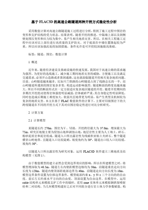
以隧道入口所出露岩性为研究对象,运用FLAC3D软件建立三维地质及结构模型(见图1)。
由于数值模型的建立必然会受到边界效应的影响,所以在所建模型之时,将模型埋深取为48.5m,隧道左右内壁距模型边缘均为50m,沿隧道垂直走向方向长度为120m,隧道内壁顶部距底部边界为40m,沿隧道走向方向长度为10m。
FLAC-3D深基坑的开挖与支护的命令流

FLAC D3深基坑的开挖与支护的命令流一、实例工程南宁地区地层属于河流阶地二元地层,广泛分布有较厚的圆砾层,国内尚无在类似地层条件下建设地铁基坑的经验,为此,可使用FLAC3D 对基坑开挖的全过程进行三维数值模拟,在对比实测数据的基础上,总结圆砾层中地铁车站深基坑的地下连续墙水平变形及周围地表沉降变形特征。
该基坑位于大学路与明秀路交叉路口处,沿大学东路东西向布置。
车站基坑长465m,标准断面宽度为20.7m,为地下两层式结构,底板埋深为15.535m(相对地面),顶板覆土厚度大于3m。
本工程主体建筑面积21163.6m2,主要结构形式为双柱三跨框架箱型结构。
本工程所处的大学路为南宁市东西向的主要交通枢纽,车流量大,人流密集,地面条件复杂。
基坑施工采用明挖顺作法施工,围护结构为800mm厚地下连续墙+内撑(三道内支撑加一道换撑)的支护体系。
第一道支撑采用钢筋混凝土支撑,尺寸为800×900mm,冠梁同时作为第一道钢筋混凝土支撑的围檩。
第二、三道支撑及换撑使用钢支撑并施加预加力,直径为609mm,壁厚为t=16mm,斜撑段采用800×1000mm钢筋砼腰梁,其余为2×I45C 钢围檩。
二、模型建立建模工作由两部分组成,实体模型部分,包括土体和地下连续墙;结构单元部分,包括混凝土支撑和钢支撑。
根据对称性原理,拟选取1/2 的实际工程尺寸进行分析。
考虑到实际的基坑长度将近500m,根据以往的经验,选取全部长度的一半虽然能够得到满意的结果,但是由于中间部分的基坑基本处于同样的受力状态,这样会使大部分的计算长度变为重复的计算,降低了计算效率。
根据初步计算结果和经验,最终确定的基坑尺寸为,宽度取基坑的最大宽度24m,开挖深度19m,基坑长度36m。
根据地勘报告,合并相似土层,模型中共划分了7个土层。
在FLAC3D 中,围护结构可以用衬砌单元(liner)或实体单元模拟。
根据Zdravdovi的研究,在二维平面基坑模拟中,分别采用实体单元和梁单元(相当于三维模型中的衬砌单元)计算所产生的墙体变形差别小于4%,而引起地表沉降的主要原因是围护结构变形造成的地层损失,可见上述两种方法计算结果的差别可忽略不计。
某隧道在锚喷支护下的FLAC3D数值分析
[1]陈育民,徐鼎平.FLAC/FLAC3D基础与工程实例[M].北京:中国水利水电出版社,2013.6
[2]刘波,韩彦辉编著FLAC原理实例与应用指南[M]北京:人民交通出版社2005
[3]王钜白石河2号隧道围岩分级与稳定性分析[D],[硕士学位论文].南昌:华东交通大学2008
作者简介:
(3)为防止拱底围岩底鼓,应即时进行支护。在选择支护措施上要根据围岩类别合理使用,尽量发挥不同支护措施的优势,在较低的成本下保证围岩的稳定性。
数值计算表明:在隧道开挖后应力场发生调整,围岩向隧道内收敛发生一定的变形,围岩发生适度的变形以释放部分应力,不致支护结构上的应力水平大幅度提高。软质岩体,隧道开挖后即使在支护条件下围岩都有不同程度的塑性变形出现。。计算分析表明,锚杆对限制围岩发生大变形效果显著,喷层对限制围岩张性破坏效果明显。随着支护措施的加强,塑性破坏区的范围明显减小;围岩整体上保持稳定。
其中:E为弹性模量、μ为泊松比。如表1所示。
2.4支护材料参数的确定
根据该隧道施工设计图纸提供的隧道支护方式:初期支护为锚喷支护,二次衬砌为模筑混凝土衬砌。在数值计算中,采用衬砌单元(shell)模拟喷射混凝土,衬砌厚为10cm。用锚索单元(cable)模拟锚杆的支护,锚杆长3.0m,锚杆间距为1.5m。锚杆及衬砌的力学参数见下表2。
3.1开挖支护后的计算结果
4.总结
(1)从图中可以看到,支护后塑性区明显比未支护的情况小了很多,支护后围岩的受力情况得到改善,竖直位移和水平位移都减少了。在位移曲线中可以明显的看到一个转折点,这是在施加初期支护后对围岩变形的限制,阻止了围岩的进一步变形所致。
(2)对软弱破碎围岩开挖后必须及时支护,如果支护不及时则使围岩物理力学性质恶化、松弛范围扩大,将造成围岩大变形、塌方等严重后果。从隧道开挖初期后的整体安全情况来看,拱肩处为最不稳定区域,其次为拱脚和拱顶[3]。
FLAC3D模拟实例循环开挖与支护

FLAC3D模拟实例循环开挖与支护nres ini.savset geometry=0.001ini ydis0ini xdis0ini zdis0ini yvel0ini xvel0ini zvel0m mprop bulk 4.0e9shear 2.5e9fri32coh 2.0e6& range grou diban-shayan;prop bulk 1.8e9shear 1.2e9fri25coh 1.0e6& range grou diban-niyan any grou hangdao any;prop bulk 1.2e9shear0.8e9fri22coh0.8e6& range grou diban-gentuyan;prop bulk 1.9e9shear 1.3e9fri24coh 1.0e6& range grou diban-tniyan;prop bulk0.7e9shear0.8e9fri21coh0.7e6& range grou mc any grou gzm any;prop bulk 3.0e9shear 2.5e9fri30coh 1.8e6& range grou dingban-fenshayan;prop bulk 1.5e9shear 1.2e9fri25coh 1.1e6& range grou dingban-niyan;prop bulk 3.5e9shear 2.5e9fri34coh 1.4e6& range grou dingban-shayan;添加接触面gen separate gzminterface1wrap mc gzminterface2wrap dingban-fenshayan gzm interface1prop kn20e9ks10e9tens1e9 interface2prop kn20e9ks10e9tens1e9set mech ratio=5e-4def excav_mcloop n(excav_p,excav_p_z+cut_liang);每次开挖量cut_0=excav_pcut_1=excav_p+cut_liang;开挖commandm null range grou gzm z cut_0cut_1step100end_commandn=excav_p+cut_Liangexcav_p=excav_p+cut_Liang;条件判断保存文件,这里判断条件必须和cut_liang对应上,否则不能得到想要的文件。
基于FLAC3D原理模拟斜井支护效果研究

交通与土木工程河南科技Henan Science and Technology总第876期第5期2024年3月收稿日期:2023-06-13基金项目:云南省科技厅重点研发计划(社会发展)(2018BC008);中国中铁科技研究开发计划课题(2020-重大专项-04);滇中引水楚雄8标科研项目(XLKK-333-2022-2024)。
作者简介:付虎 (1995—),男,硕士,助理工程师,研究方向:隧道及地下工程。
通信作者:张庆文(1966—),男,博士,教授,研究方向:岩石力学及隧道工程。
基于FLAC 3D 原理模拟斜井支护效果研究付 虎 耿 赟 李元松 张庆文(西南林业大学,云南 昆明 650224)摘 要:【目的】斜井介于平港和竖井之间,结构受力具有一定的复杂性,因此研究斜井硐室开挖和支护的有效性和可行性尤为重要,有必要对斜井支护效果展开研究。
【方法】采用FLAC 3D 对斜井围岩变形及支护技术方案的应力场、位移场和塑性区的分布变化情况进行数值模拟分析。
【结果】在斜井开挖过程中,未支护工况下城门型斜井拱腰、拱顶、拱脚及底板等三处是开挖围岩最不稳定区域。
支护后的围岩应力场、位移场和塑性区的分布减少了较多,其中,拱顶下沉位移量从57 mm 降至5.3 mm ;拱腰处水平位移量从26.7 mm 降至15.7 mm ;底板水平位移量从11.3 mm 降至7.14 mm 。
【结论】在支护工况下的围岩应力场、位移场和塑性区的分布得到了较好改善,对斜井围岩的位移变形、塑性区范围起到了显著的控制作用。
关键词:滇中引水;初期支护;斜井开挖;FLAC 3D 模拟中图分类号:TV68 文献标志码:A 文章编号:1003-5168(2024)05-0053-06DOI :10.19968/ki.hnkj.1003-5168.2024.05.011Research on the Supporting Effect of Inclined Shaft Simulation Basedon FLAC 3D PrincipleFU Hu GENG Yun LI Yuansong ZHANG Qingwei (Southwest Forestry University, Kunming 650224, China)Abstract: [Purposes ] The inclined shaft is between the flat port and the shaft, and the structural stresshas certain complexity. Therefore, it is particularly important to study the effectiveness and feasibility of the excavation and support of the inclined shaft chamber, and it is necessary to study the supporting ef⁃fect of the inclined shaft. [Methods ] FLAC 3D was used to conduct numerical simulation analysis of the distribution changes of stress field, displacement field and plastic zone of the surrounding rock deforma⁃tion and support technical scheme of inclined shaft. [Findings ] In the process of excavation of inclined shafts, the arch, vault, arch foot and floor of the gate-type inclined shaft were the three most unstable ar⁃eas of excavation surrounding rock under unsupported conditions. The distribution of stress field, dis⁃placement field and plastic zone of surrounding rock after support is reduced, and the displacement of vault subsidence is reduced from 57 mm to 5.3 mm. The horizontal displacement at the arch decreases from 26.7 mm to 15.7 mm. The horizontal displacement of the floor decreases from 11.3 mm to 7.14 mm.[Conclusions ] The distribution of stress field, displacement field and plastic zone of surrounding rock under supporting conditions is well improved, which plays a significant role in controlling the displace⁃ment deformation and plastic zone range of surrounding rock of inclined shaft. Keywords: water diversion in central Yunnan; initial support; inclined shaft excavation; FLAC3D simula⁃tion0 引言滇中引水工程是云南省重要的水利项目之一,是云南省的民生福祉工程[1-2]。
基于flac3D深基坑开挖模拟与支护设计

本科生毕业论文(设计)题目:基于flac3D深基坑开挖模拟与支护设计指导教师: 职称:评阅人: 职称:摘要随着城市化过程中不断涌现的高层建筑和超高层建筑以及城市地下空间的开发,深基坑工程越来越多,深基坑工程项目的规模和复杂性日益增大,给深基坑工程的设计和施工带来了更大的挑战。
在这样的背景下,深基坑支护结构设计和变形量预测已成为岩土工程领域的重要研究课题之一。
本文以武汉市万达广场深基坑工程作为研究对象,利用勘查资料和深基坑支护结构设计要求,比选合理的基坑支护方案并进行相应的计算设计。
同时,本文针对深基坑工程变形量验算等难以解决的问题引用了flac3D数值模拟方法,对基坑开挖、支护结构施工进行全方位的模拟监测,将计算设计结果和模拟计算结果进行对比验算,得出比较合理的支护结构设计方案和变形量控制方案。
根据基坑实际情况和勘查资料,本文选择的围护方案为以大直径混凝土排桩、双排桩、角撑与对顶撑相结合的内支撑为主的多种联合支护方案,结合坡顶大面积卸土减载、坑内被动区加固的措施。
计算部分主要设计计算大直径混凝土排桩(钻孔灌注桩)桩长、内力和配筋,而对卸土减载、内支撑结构、坑内被动区加固和降水设计只进行了简要的说明;flac3D模拟部分主要从建立模型、设置大直径混凝土排桩、放坡开挖、放坡坡面土钉施工、预应力锚索(代替内支撑)施工和基坑主体开挖为顺序进行建模计算,最后进行变形量监测、分析,输出桩单元、锚单元的内力分布情况并给出相应的结论与建议。
本文以常规计算和数值模拟相结合的方式进行参考对比,常规计算和数值模拟分析结果非常接近,给出了有效合理的安全系数。
关键词:深基坑支护设计flac3D模拟数值模拟AbstractWith the urbanization process ,high-rise buildings and supertall buildings are continuously emerging .As a result ,underground space development project and deep excavation project become more and more. At the same time, the scale and complexity of deep excavation increasing bigger. they make the design and construction of deep excavation to face greater challenges. So structural design and deformation prediction of deep excavation has become an important research issue in the field of geotechnical engineering. In this paper, the deep excavation of Wanda Plaza, Wuhan is studied. And using survey data and structural design of deep excavation requirements to select reasonable foundation pit ,then to conduct the corresponding design. The meantime, as checking the deformation of deep excavation is a difficult problems ,it uses flac3D numerical simulation method to monitor the progress of deep pit’s excavation, construction .Then comparing the design results of the calculation and simulation results to obtained reasonable support structure design and control program of deformation.According to the actual situation and exploration data, the envelope of large diameter piles concrete piles, angle brace and top brace on the combination of a variety of internal support-based programs are selected, combined with slope Top large dump load shedding and the reinforcement measures of pit passive zone.1) The calculation part of the paper mainly introduce the design and calculation of large diameter concrete piles or bored pile, and the rest just briefly introduce the dumping load shedding, internal support structure, the pit design of passive zone strengthening and precipitation.2) With flac3D, successively study the model building, setting large diameter concrete piles, sloping excavation, soil nailing construction, pre-stressed cable (instead of internal support) construction and excavation for the foundation pit .Finally, conduct the deformation monitoring , output pile element, the internal force distribution analysis in anchorage unit .And then, provide the corresponding conclusions and recommendations.In this paper, conventional calculations and numerical simulation methods are used. And their results were very close. So it can give an effective and reasonable safety factor through the combination of these methods.Key words: deep excavation design flac3D numerical simulation目录第一章绪论 (1)第一节选题思路 (1)第二节设计流程 (1)第二章工程概况及场地工程地质条件 (3)第一节工程概况 (3)第二节场地工程地质条件 (4)第三章A-OPQRSA段基坑支护结构设计 (10)第一节设计依据 (10)第二节设计参数 (10)第三节A-OPQRSA段基坑支护方案选择 (11)第四节A-OPQRSA段基坑减载放坡设计 (13)第五节A-OPQRSA段基坑支护桩设计 (13)第六节A-OPQRSA段基坑地下水控制方案设计 (24)第四章基于flac3D基坑开挖模拟分析 (27)第一节关于flac3D的概述 (27)第二节基坑维护方案 (27)第三节计算模型及参数 (28)第四节初始应力计算 (29)第五节支护桩施工 (31)第六节模拟分层开挖和设定锚杆 (32)第七节设置采样记录变量 (34)第八节计算结果分析 (35)第五章结论与问题 (44)第一节结论 (44)第二节设计过程中存在问题 (45)致谢 (47)参考文献 (48)附录 (49)第一章绪论第一节选题思路深基坑工程设计是当今岩土工程界关注的热点话题,深基坑工程的难题在于对变形量的预测,基坑允许的变形、垂直位移的计算是比建筑物自身允许的沉降和沉降计算更为复杂的课题,但又是基坑工程尤其是在软土地区和工程地质、水文地质复杂地区无法回避的问题。
flac3d基坑开挖支护例子

;;;;;;;;;;;;;;;;;;;;;;;;;;;;;;;;;;;;;;;;;;;;;;;;;;;;;;;;;;;;;;;;;;;;;;;;;;;七区(??侧帮 喷层???)
p4 6,20,10.865 p5 2.1,20,12 p6 6,0,11.02 p7 6,20,11.02 &
size 8 20 1 ratio 1 1 1 group n3
;;;;;;;;;;;;;;;;;;;;;;;;;;;;;;;;;;;;;;;;;;;;;;;;;;;;;;;;四区
;part1
;;;;;;;;;;;;;;;;;;;;;;;;;;;;;;;;;;;;;;;;;;;;;;;;;;;;;;一区
gen zone radcyl p0 0,0,13.4 p1 6,0,12.41 p2 0,20,13.4 p3 0,0,16.7 &
p4 6,20,12.41 p5 0,20,16.7 p6 6,0,15.13 p7 6,20,15.13 &
p4 15,20,7.36 p5 6,20,11.02 p6 15,0,8.6 p7 15,20,8.6 &
size 12 20 8 ratio 1.05 1 1 group n3
;;;;;;;;;;;;;;;;;;;;;;;;;;;;;;;;;;;;;;;;;;;;;;;;;;;;;;;;;;;;十一区
p4 6,20,9.935 p5 1.5,20,12 p6 6,0,10.865 p7 6,20,10.865 &
size 8 20 6 ratio 1 1 1 group n3
- 1、下载文档前请自行甄别文档内容的完整性,平台不提供额外的编辑、内容补充、找答案等附加服务。
- 2、"仅部分预览"的文档,不可在线预览部分如存在完整性等问题,可反馈申请退款(可完整预览的文档不适用该条件!)。
- 3、如文档侵犯您的权益,请联系客服反馈,我们会尽快为您处理(人工客服工作时间:9:00-18:30)。
FLAC3D模拟实例循环开挖与支护nres ini.savset geometry=0.001ini ydis0ini xdis0ini zdis0ini yvel0ini xvel0ini zvel0m mprop bulk 4.0e9shear 2.5e9fri32coh 2.0e6& range grou diban-shayan;prop bulk 1.8e9shear 1.2e9fri25coh 1.0e6& range grou diban-niyan any grou hangdao any;prop bulk 1.2e9shear0.8e9fri22coh0.8e6& range grou diban-gentuyan;prop bulk 1.9e9shear 1.3e9fri24coh 1.0e6& range grou diban-tniyan;prop bulk0.7e9shear0.8e9fri21coh0.7e6& range grou mc any grou gzm any;prop bulk 3.0e9shear 2.5e9fri30coh 1.8e6& range grou dingban-fenshayan;prop bulk 1.5e9shear 1.2e9fri25coh 1.1e6& range grou dingban-niyan;prop bulk 3.5e9shear 2.5e9fri34coh 1.4e6& range grou dingban-shayan;添加接触面gen separate gzminterface1wrap mc gzminterface2wrap dingban-fenshayan gzm interface1prop kn20e9ks10e9tens1e9 interface2prop kn20e9ks10e9tens1e9set mech ratio=5e-4def excav_mcloop n(excav_p,excav_p_z+cut_liang);每次开挖量cut_0=excav_pcut_1=excav_p+cut_liang;开挖commandm null range grou gzm z cut_0cut_1step100end_commandn=excav_p+cut_Liangexcav_p=excav_p+cut_Liang;条件判断保存文件,这里判断条件必须和cut_liang对应上,否则不能得到想要的文件。
if cut_1=40thencommandsave kwmc40m.savend_commandend_ifend_loopend;每次需要修改set cut_liang=5excav_p=0excav_p_z=80excav_mcsolvepl block groupl add axes redpl set rotation9000save kwmc2.savcall kwhdno.txt;n;res kwmc.savini ydis0ini xdis0ini zdis0ini yvel0ini xvel0ini zvel0set largeset mech ratio=5e-4pl cont ydis shad on outline onhis gp ydis901740;40m处巷道巷道顶部中点his gp xdis77.7514.7540;40m处巷道巷道左帮中点his gp xdis82.2514.7540;40m处巷道巷道右帮中点def excav_hangdaoloop n(excav_p,excav_p_z+cut_liang);每次开挖量cut_0=excav_pcut_1=excav_p+cut_liang;开挖commandm null range grou hangdao z cut_0cut_1step50end_commandn=excav_p+cut_Liangexcav_p=excav_p+cut_Liang;条件判断保存文件,这里判断条件必须和cut_liang对应上,否则不能得到想要的文件。
if cut_1=40thencommandsave kwhdno40m.savend_commandend_ifend_loopendset cut_liang=8excav_p=0excav_p_z=80excav_hangdaosolvesave kwhdno2.savcall kwhdzh.txt;n;res kwmc2.sav;pl set rot901800;从后视图看,零点面对着;pl set rot9000;从前视图看,终点面对着pl set rot907515pl cont syy range grou hangdaopl add sel geom node off fill on black blue;显示支护单元;pl add sel geom cable blue;sel set damp combined;sel liner prop slide on;添加接触面;gen separate2;inter1wrap12;inter2wrap32;inter1face range plane norm010ori011.08150dist 0.1;inter2face range plane norm010ori010.71930dist 0.1;interface1prop kn1e10ks1e10;interface2prop kn1e10ks1e10set largeini ydis0ini xdis0ini zdis0ini yvel0ini xvel0ini zvel0set largeset mech ratio=5e-4his gp ydis901740;40m处巷道巷道顶部中点his gp xdis77.7514.7540;40m处巷道巷道左帮中点his gp xdis82.2514.7540;40m处巷道巷道右帮中点;监控锚杆索命令;his sel cable force x y z;his sel cable stress x y z;his sel cable grout stress x y z;监控锚杆索构件端部水泥浆应力(端部);his sel cable grout slip x y z;滑动状态(端部)(0未屈服1正在屈服2曾屈服);his sel cable grout disp x y z;监控锚杆索构件端部在水泥浆中的位移;———————————————————————————————————;—————————————————————————————————————————————;锚杆(索)、初撑参数及剖面位置参数;; ;—————————————————————————————————————————————;———————————————————————-————————————def maogan_canshucable_seg=10;构件数emod_e=180e9;弹性模量xcarea_x=3.46185e-4;锚杆(索)横截面积ytens_y=25e4;抗拉强度gr_per_gp=0.11;水泥浆外圈长度gr_k_gk=6e6;单位长度上水泥浆刚度gr_fric_gf=30.0;水泥浆摩擦角gr_coh_gc=1.0e5;单位长度上水泥浆的粘结力;ycomp_y=;抗压强度enddef maosuo_canshus_cable_seg=12;构件数emod__e=200e9;弹性模量xcarea__x=3.46185e-4;锚杆(索)横截面积ytens__y=35e4;抗拉强度gr_per__gp=0.11;水泥浆外圈长度gr_k__gk=6e6;单位长度上水泥浆刚度gr_fric__gf=30;水泥浆摩擦角;gr_coh__gc=;单位长度上水泥浆的粘结力;ycomp__y=;抗压强度endmaogan_canshu maosuo_canshudef maogan(suo)_p ;锚杆位置;maogan1xp1=77.75yp1=14.0xp1_2=72.25yp1_2=14.0;maogan2xp2=77.8686yp2=15.4709xp2_2=75.5004yp2_2=16.2719;maogan3xp3=79.0593yp3=16.7939xp3_2=78.0140yp3_2=19.0649;maogan4xp4=80.9407yp4=16.7939xp4_2=81.9680 yp4_2=19.0649 ;maogan5xp5=82.1314yp5=15.4709xp5_2=84.4996 yp5_2=16.2719 ;maogan6xp6=82.25yp6=14.0xp6_2=84.75yp6_2=14.0;;锚索位置;maosuo1xps1=77.75yps1=13.3536 xps1_2=71.25 yps1_2=13.3536 ;maosuo2xps2=77.75yps2=14.75xps2_2=71.25 yps2_2=14.75;maosuo3xps3=78.3554 yps3=16.2638 xps3_2=73.5264 yps3_2=20.6368 ;maosuo4xps4=80.0yps4=17.0xps4_2=80.0yps4_2=23.5;maosuo5xps5=81.6646 yps5=16.2638 xps5_2=86.4736 yps5_2=20.63668 ;maosuo6xps6=82.25yps6=14.75xps6_2=88.75yps6_2=14.75;maosuo7xps7=82.25yps7=13.3336xps7_2=88.75yps7_2=13.3536endmaogan(suo)_p;;;开挖量、范围、支护排距控制等参数def excav_canshucut_x=80.0cut_y=14.75cut_r=2.25;开挖巷道半圆拱的中心坐标及半径cut_zhiqiang=1.5;直墙壁高度;cut_0=0.0;开挖起始位置cut_Liang=10;一次开挖量cut_1=cut_0+cut_liangexcav_p_z=80.0;开挖终点位置;paiju=1.0;支护断面间的排距first_p=0.0;开挖起始段第一排支护的位置,参数first_p需要根据前一开挖段剩下的排距大小调整endexcav_canshugen separate hangdao;添加初衬liner或shell单元前需要产生一分离单元面;开挖与支护def excavandzhihuexcav_p=cut_0loop n(excav_p,excav_p_z+2*cut_liang);(2是参数,防止循环跳出,未装锚杆索,下个循环中亦是如此);每次开挖量cut_0=excav_pcut_1=excav_p+cut_liang;;下面的参数是控制添加初衬单元范围,1.1为参数,可更改。