
FCH-230剥线机详细说明
全自动电脑剥线机使用说明书 1 本系统特点
1、 采用最新的32位Cortex-M3内核处理器,运行速度为单周期72M; 2、 5路高达100K的脉冲输出,脉冲型式为“脉冲+方向”、集电极开路输出; 3、 7路高速输入点!响应时间小于2uS; 4、 4路集电集开路输出,输出电流5A; 5、 板上集成了标准的RS485通信接口,并配有Modbus RTU通信协议,可以方便的与各种品牌的触摸屏通信,通信数据格式为38400、8、n、1; 6、 板上已配置步进驱动器的驱动电源整流电路,可为驱动器提供15A驱动电流,使机器的电路配线更简单;机器在停机状态下该整流电路停止输出;可以在不断电的情况下调整机械部分; 7、 配有大容量存储器,可以同时保存100组参数,方便操作者操作; 全自动电脑剥线机使用说明书
2 目录 1. 电气连接说明; 2. 操作说明; 3. 通信协议介绍; 4. 裁线范例 全自动电脑剥线机使用说明书
3 一、 电气连接说明
备注: 1、 变压器T1推荐规格为220V/7.5V 10W; 2、 变压器T2推荐规格为220V/18V、45V 3、 电机驱动信号为脉冲+方向,最高输出频率为100K,无需加限流电阻; 4、 使用485通信总线,应保证同一条总线上不应超过32台从机! 5、 改变任何接线时应关闭电源,以防触电; 全自动电脑剥线机使用说明书 4 二、操作说明
控制面板图
本系统的操作介面由23只按键和一块192x64点阵的液晶显示屏组成,以下将介绍每个按键的功能:
:在待机状态下,每短按一次,机器执行一单步,反复循环;连继按下超过约0.5秒,机器将自动运行一循环;该按键在调机时作用非常大;
:在待机状态下,按下此键,机器开始工作; :在工作状态下,按下此键,机器将完成本次工作后停机; :在待机状态下,按下此键,机器将执行复位动作; 在工作状态下,按下此键,机器先停机,后再执行复位动作;
:在数据输入状态下按下此键,输入数字0;在待机状态下按下此键,机器将进入剥线参数设置状态; 全自动电脑剥线机使用说明书 5 :在数据输入状态下按下此键,输入数字1;在待机状态下按下此键,机器将进入剥线速度设置状态;
:在数据输入状态下按下此键,输入数字2;在待机状态下按下此键,机器将进入扭线参数设置状态;
:在数据输入状态下按下此键,输入数字3;在待机状态下按下此键,机器将根据当前的功能进入相应的功能设置画面;
:在数据输入状态下按下此键,输入数字4;在待机状态下按下此键,总量清0;
:在数据输入状态下按下此键,输入数字5;在待机状态下按下此键,把数清0;
:在数据输入状态下按下此键,输入数字6;在待机状态下按下此键,切换机器工作模式;
:在数据输入状态下按下此键,输入数字7;在待机状态下按下此键,切换机器工作模式;
:在数据输入状态下按下此键,输入数字8;在待机状态下按下此键,机器将进入产量设置状态;
:在数据输入状态下按下此键,输入数字9;在待机状态全自动电脑剥线机使用说明书 6 下按下此键,机器将进入功能设置画面;
:在数据输入状态下按下此键,清除已输入的数据;在待机状态下按下此键,总产量和把数全部清0;
:在待机状态下按下此键,机器将进入程序设置状态; :在参数设置下按下该键,被设置参数最低位加1;在非参数设置状态下按下此键,刀值加1;
:在参数设置下按下该键,被设置参数最低位减1;在非参数设置状态下按下此键,刀值减1;
:在参数设置状态下按下此键,当前修改的数据放弃,上一个数据变成修改的对象;
:在参数设置状态下按下此键,当前修改的数据放弃,下一个数据变成修改的对象;
:在参数设置状态下按下此键,当前修改的数据将保存并写入EEPROM,并将下一个数据变成修改的对象;
:在参数设置状态下按下此键,退出参数设置状态;在功能设置画面、多段剥皮设置画面、系统设置画面下。按一此键,返回工作画面;
:在待机画面下,按下该键,进入系统设置画面,进入之全自动电脑剥线机使用说明书 7 前,需先输入密码;在功能设置画面、多段剥皮设置画面、系统设置画面,按下该键,进入参数设置状态;
工作画面: 机器上电后,屏幕显示开机画面,约三秒后将显示本画面;机器开始运行时,屏幕一定在的这个画面上;否则,机器无法启动;
功能显示区: 本机有:长线、短线、护套、排线、多段、高速6种工作模式
参数编号: 可保存0-99号参数
扭线功能区: 依次为:前端扭线方式;后端扭线方式;扭线速度;扭线强度 速度显示区: 依次为:刀座速度;送线速度;剥皮速度 暂停时间:把数达到后;暂停这个时间后,继续工作
前端剥皮长度 前端半剥长度 线材总长度 后端半剥长度 后剥剥皮长度 剥线刀值 退刀值 设定总量
实际工作总量
实际工作把数
设定单把数量 全自动电脑剥线机使用说明书
8 剥线参数设置:机器待机时(没有裁线),按下键;前端长度参数开始闪烁,此时可以直接输入数字,如果
输入有误,可按键清除已输入的数字后再重新输入;然后按键保存,并且下一项参数闪烁,直至将前端长度、前端半剥、总长度、后端半剥、后端长度、刀值、退刀全部输入完成;
参数设置中;按键将闪烁参数前移一项;按键将闪烁参数后移一项;随时可以按退出参数设置,回到待机状态;
剥线速度设置:机器待机时(没有裁线),按下键;切刀速度参数开始闪烁,此时可以直接输入数字,如果
输入有误,可按键清除已输入的数字后再重新输入;然后按键保存,并且下一项参数闪烁,直至将切刀速度、送线速度、剥线速度、暂停时间全部输入完成;
参数设置中;按键将闪烁参数前移一项;按键将闪烁参数后移一项;随时可以按退全自动电脑剥线机使用说明书 9 出参数设置,回到待机状态;
产量设置: 机器待机时(没有裁线),按下键;总量设置参数开始闪烁,此时可以直接输入数字,如果
输入有误,可按键清除已输入的数字后再重新输入;然后按键保存,并且下一项参数闪烁,直至将设置总量、设置把数全部输入完成;
参数设置中;按键将闪烁参数前移一项;按键将闪烁参数后移一项;随时可以按退出参数设置,回到待机状态;
扭线设置: 机器待机时(没有裁线),按下键;前端扭线模式闪烁,此时按、键切换,然后按键保存,并且下一项参数闪烁,直至将前端扭线模式、后端扭线模式输入完成后,再按前面的方法输入扭线速度、扭线强度;
参数设置中;按键将闪烁参数前移一项;按键将闪烁参数后移一项;随时可以按退出参数设置,回到待机状态; 全自动电脑剥线机使用说明书 10 程序编号设置:机器待机时(没有裁线),按下键;程序参数开始闪烁,此时可以直接输入数字,如果输入
有误,可按键清除已输入的数字后再重新输入;然后按键保存;回到待机状态; 工作模式切换: 机器待机时(没有裁线),按下、键切换工作模式;
工作模式说明: 本机为多功能裁线机,共设为6种裁线剥皮程序,以下分别图片方式说明: 全自动电脑剥线机使用说明书 11 长线模式:
该模式与传统220裁线机功能一致,可安装扭线装置以增加扭线功能,线材长度关系如下图,只需按上面介绍的方法输入所需的尺寸
即可,该模式下键功能不可用;
短线模式: 全自动电脑剥线机使用说明书
12 该模式调机方式与长线基本相同,只是机器的剥线动作不一样;
并且没有扭线功能;该模式下键功能不可用; 排线模式:
该模式调机方式与长线基本相同,只是机器在送线时多了一个
分线动作;并且没有扭线功能;该模式下按键功能进入以下
排线功能设置画面:
按下键开始设置参数,设置完成后,按键返回工作画设置分线刀模与切刀的距离,以作为程序分线的时间;
设置分线气缸回
位所需的时间,根据实际需要调整,以达到最高工作效率;
设置分线气缸压合所需的时间,根据实际需要调整,以达到最高工作效率; 全自动电脑剥线机使用说明书
13 面;
多段模式:
本模式没有扭线功能;按键功能进入以下排线功能设置画面:
在非参数设置状态下,按、可向上或向下查看1-12段的设置参数;
第一段的设置总长度:即胶皮长度,后面范例中有说明 第一段的设置剥皮长度:即剥掉胶皮部分的长度,后面范例中有说明
前端长度 前端半剥 线材总长度,无需设置程序会自动拫据所有的端长度计算出来 后端半
剥 后端长度,无需设
置,程序会自动将最后一的剥皮长度当作后端长度
Z230中文资料

0.25 0.25 0.25 0.25 0.25 0.25 0.25 0.25 0.25 0.25 0.25 0.25 0.25 0.25 0.25 0.25 0.25 0.25 0.25 0.25 0.25 0.25 0.25 0.25
5000 5000 5000 5000 5000 5000 5000 5000 5000 5000 8000 9000 9000 9000 9000 9000 9000 9000 9000 9000 9000 9500 9500 9500
SINGLE PHASE HALF WAVF 60HZ RESISTIVE OR INDUCTIVE LOAD 0.375”(9.5mm) LEAD LENGTHS
0
VZ, ZENER VOLTAGE (VOLTS)
LEAD TEMPERATURE, ℃
FIG. 3 - TYPICAL INSTANTANEOUS FORWARD CHARCTERISTICS INSTANTANEOUS FORWARD CURRENT, AMPERES 10 INSTANTANEOUS REVERSE CURRENT,MICROAMPERES
INSTANTANEOUS FORWARD VOLTAGE, VOLTS
FIG. 5 - TYPICAL TEMPERATURE COEFFICIENTS θ VZ TEMPERATURE COEFFICIENT (mV/℃) @ IZT ℃ 1000 500 200 100 50 20 10 10 20 50 100 200 400 1000
5 5 5 5 5 5 5 5 5 5 5 5 5 5 5 5 5 5 5 5 5 5 5 5
750 750 850 1000 1200 1300 1500 2200 2200 2500 2500 5000 5000 5000 5000 5000 5000 5000 5000 5000 5000 5000 5000 5000
凯塔(Cat)BH130智能回挖机文档说明书

BH130 SMART BACKHOE2BH130 SMART BACKHOEThe Cat BH130 Smart Backhoe is used for digging footings, drainage ditches, utility trenching, backfilling and maintaining slopes and embankments in a variety of construction, industrial and landscape settings. When paired with Cat hammers, the backhoe is ideal for demolishing concrete. Equipped with an optional thumb, it can be used for handling brush and bulky objects, such as rocksand stumps. With an auger, it does extremely well at drilling holes for fence posts, trees and shrubs.PRODUCTIVITY AND MANEUVERABILITYIn-cab operation increases productivity by reducing the amount of time required to reposition compared to traditional skid steer loader backhoes, allowing for faster cycle times than competitive units. The compact package of the machine and backhoe allows the operator to maneuver more easily in confined areas and leaves more trailer space for Cat work tools.“BEST-IN-CLASS” COMFORT+Operators can dig, excavate, side-shift, and even reposition the machine and backhoe without ever leaving the seat.+Remain in the cab for extended periods of time, with little fatigue since the cab offers comfort and cover from extreme temperatures or inclement weather conditions.EXCAVATION REACHReach 3 meters or 10 feet for utilities, footers, and deeper trenches inexcavation projects.SMART ATTACHMENTEnable smart attachment screen atmachine startup to switch to dig mode.DEDICATED DISPLAYIntegrated operation with dedicateddisplay for settings and activation.PATTERN SELECTIONBoth backhoe loader and excavator control patterns are available and easily changedon the machine’s display screen.EXISTING MACHINE JOYSTICKS+Existing seat mounted joystick controls eliminate the need to remove the door for operation.+Easily change from drive mode toattachment mode with the right trigger.HYDRAULIC SIDE-SHIFT AND STABILIZERS+Side-shift provides the ability to position boom close to walls to dig, expose brick ledges, backfill and widen trenches.+Stabilizers provide additional stability.STANDARD TWO YEAR WARRANTYStandard two year warranty gives you peace of mind when purchasing a quality Cat backhoe attachment.FEATURES3BH130 SMART BACKHOE SPECIFICATIONSBH130 SMART BACKHOE ATTACHMENTAEHQ8398 (10-2021)(Global)For more complete information on Cat products, dealer services and industry solutions, visit us on the web at © 2021 Caterpillar. All Rights Reserved.Materials and specifications are subject to change without notice. Featured machines in photos may include additional equipment. See your Cat dealer for available options.CAT, CATERPILLAR, LET’S DO THE WORK, their respective logos, “Caterpillar Corporate Yellow,” the“Power Edge” and Cat “Modern Hex” trade dress as well as corporate and product identity used herein, are trademarks of Caterpillar and may not be used without COMPATIBLE TOOLSBH130 SMART BACKHOE ATTACHMENTAUXILIARY LINES STANDARDHYDRAULIC SIDE-SHIFTHYDRAULIC STABILIZERSTHUMB MOUNTINGSTANDARDCOMPATIBLE WITH3-TON EXCAVATOR ATTACHMENTSCat 3-ton excavator attachments can easily be used and exchanged with coupler for increased versatility.。
Endress+Hauser Prosonic T系列产品说明说明书

Technical Information TI 246F/00/enApplicationThe Prosonic T is a compact ultrasonic transmitter for continuous non-contact level measurement in liquids and in coarse-grained or pelleted solids. The Prosonic T series consists of three transmitters, which can be equipped with one of several electronic modules,with graduated measuring ranges from 0.25 m (0.8 ft) upwards.•FMU 130, 230in coarse-grained solids (grain size from 4 mm/0.16 in) up to 2 m/6.6 ft in liquids up to 5 m/16.4 ft (2 wire instruments: 4 m/13 ft)•FMU 131, 231in coarse-grained solids (grain size from 4 mm/0.16 in) up to 3.5 m/11.5 ft in liquids up to 8 m/26.2 ft (2 wire instruments: 7 m/23 ft)•FMU 232in coarse-grained solids (grain size from 4 mm/0.16 in) up to 7 m/23 ft in liquids up to 15 m/49.2 ftAll transmitters are equipped with an integrated temperature sensor for time-of-flight compensation.Features and Benefits Fits exactly to the process•Threaded connections from G 11/2or 11/2NPT or flange 4" or DN 100•Fully rotatable housing•LEDs visible through housing cover allow quick monitoring of operational statusElectronics versions•FMU 130,131:2-wire loop-powered general approval for ATEX II 2 G EEx ia•FMU 230,231:2-wire loop-powered or 4-wire including mains power supply •FMU 232: 4-wire, optional approval for ATEX II 1/3 D including mains power supplyIntelligent operation and evaluation •Simple local push-button operation,with optional display•HART protocol for remote operation •Digital communication with PROFIBUS-PAHART is a registered trademark of the HART Communication FoundationUltrasonic Level Measurement prosonic T FMU 130, 131prosonic T FMU 230, 231, 232Compact transmitter for continuous,non-contact level measurementAvailable as a Smart transmitter orfor connection to process control systemsHauser+Endress The Power of Know HowMeasuring SystemThe Prosonic T compact ultrasonic transmitter is a complete measuring point within itself. The simplest version allows access to all functions required for basic operation. Calibration can be carried out using the four pushbuttons –,+, V , H on the instrument without the need for other equipment.With a plug-in display, the complete Endress+Hauser user matrix can be accessed.The basic functionality may beenhanced by other optional operating possibilities or integration into a process control system, e.g. via:•2-wire loop-powered 4…20 mA (Smart) with INTENSOR or HART protocol or for connection to PROFIBUS-PA bus systems•4-wire, with separate power supply,4…20 mA (Smart) with HART protocol2-wire 4…20 mA Loop-PoweredApplications in e.g. Storage VesselsFMU 130, FMU 131:Certificate ATEX II 2 G EEx ia FMU 230, FMU 231: Standard4-wire, 4…20 mASeparate Power SupplyApplications with Rapid Changes inFMU 230, FMU 231: Standard FMU 232: Optional ATEX II 1/3 D2Power supply via the transmitter power pack e.g.PLC,with FMU 130, 131 connection via the Ex isolator (Zener barrier:<30 V DC output voltage, <200 mA, <1 W):operation via handheld terminal (protocol:INTENSOR, HART)y FXN 671:operation via Rackbus or handheld terminal (protocol:INTENSOR)z Silometer FMX 770:operation via Commutec transmitter (protocol:INTENSOR){Connection to PROFIBUS-PA bus for up to 10 transmitters, operated by a PC|Commubox:interface to a PC for Smart transmitters, operated by a PC (protocol:INTENSOR, HART)Operation via HART protocol:point-to-point using handheld terminal or PC (Commubox)OperationProsonic T compact transmitters offer operation tailored to all level applications:•Local calibration or matrix operation by simply pressing buttons•Smart – remote operation and display via the handheld terminal•Comprehensive operating and display software for personal computer •Calibration in the control room via a Silometer FMX 770or FXN 671.Matrix OperationProsonic T can be operated by using the keyboard and display, a handheld terminal, a Silometer transmitter(FMX 770, FXN 671) or via a process bus. The identical operating matrice ensure that procedures are uniform and clear.Operation via DisplayParameters are entered and valuesdisplayed by using the four pushbuttons –,+,V ,H on the front panel of the device.The optional display provides access to the Endress+Hauser operating matrix and to a wide selection of additional functions.•The following application parameters are available:−Liquid−Rapid changes in levels of liquids −Measurement when mounted in the dome cover−Coarse-grained solids −Conveyor belt•Automatic suppression of three fixed target echoes•Linearisation (11 points)•First echo detection (double echo)•Automatic suppression of stirrer echoesOperation Without a DisplayThe basic functions of the Prosonic T can be set by using just the fourpushbuttons –, +, V , H on the front panel of the instrument.•Empty and full calibration•Parameter protection by entry locking3Local matrix operation via display Setting basic functions locally using four pushbuttonsPROFIBUS-PAThe PROFIBUS-PA is an open fieldbus standard for connecting sensors and actuators, which may also be inexplosion hazardous areas, to one bus cable. The two-wire sensors are supplied with power over the PROFIBUS-PA and the process information of the sensor is digitally transmitted.The number of instruments operated at one bus segment:•up to 10 for EEx ia applications •up to 32 for non-Ex applicationsOperation via Handheld Terminal With a handheld terminal,the Prosonic T can be configured,values displayed and additional functions activated from anywhere on the 4…20mA signal line.There are two versions:•Commulog VU 260 Z (INTENSOR)•Universel HART Communicator DXR 275Operation with Commubox Commubox FXA 191 connectsintrinsically safe Smart transmitters with INTENSOR or HART protocols to the RS 232 C serial interface of a personal computer, allowing remote operation by the Endress+Hauser Commuwin II operating program.4Connecting handheld terminalsConnecting the CommuboxA Prosonic T with the PROFIBUS-PA protocol allows:•local operation with display•matrix operation with a personal computer and the Commuwin II operating program running under MS Windows 3.11Installation Mounting•Always mount the sensor such that thedistance between it and the maximumproduct level exceeds the blockingdistance.The lower edge of thetransmitter should,however,projectbelow the roof of the tank or silo.Exception:mounting in a nozzle.•Never mount two Prosonic T in avessel because the instruments maynot function correctly.•Do not mount the sensor in the centre ofthe vessel roof.•Position the sensor at right angles tothe surface of the material.•Do not measure through the fillingcurtain.Blocking DistanceDue to the ringing time of the sensor, there is a zone immediately below it in which returning echoes cannot be detected. This so-called blocking distance determines the minimum distance between the sensor and the maximum level in the tank or silo (see Technical Data for values).Interference Suppression Interference echoes coming from internal fittings can be suppressed by using the fixed target suppression function. The signals are then no longer recorded or used for further processing. The ultrasonic pulse leaves the sensor as a narrow beam which widens with increasing distance from the device. Every object within this beam produces an interference echo which is received by the sensor.Mounting on a NozzleIf the maximum level to be measured falls within the blocking distance, the transmitter must be mounted on a nozzle.•No build-up should form in the nozzle.•The recommend nozzle dimensions are limits, within which the nozzle can vary. Check that the nozzle diameter is large enough, but keep the nozzle length to a minimum (see figure).•The inner surface of the nozzle should be as smooth as possible – no edges or welding seams.Other Types of Mounting•below left:mounting with welded sleeve •below right:mounting with counter nut5LD DDimensions without Display Counter nutMeasuring RangeThe maximum measuring range of the Prosonic T is limited by the conditions at the measuring point and the reflection characteristics of the product surface. Optimum conditions are achieved if:•the surface of the liquid is calm and without foam,•no large concentrations of vapour are present in the tank,•the solid material is hard andcoarse-grained,•no dust is present in the silo,•temperature layering in the tank or silo is low.Example for Calculating RangeCheck the factors affecting your measurement in the table to the right. Add up their attenuation values (dB).•Temperature difference in silo max. 40°C•Low amount of filling curtain in detection area•Surface of liquid with strong turbulenceSum of attenuation valuesRange below these factors thus approx. 5.8 m (19 in) with 2" sensor.Effects Attenuation(dB) Temperature layeringFor air temperature differencebetween sensor and productsurface up to 20°C (68°F)up to 40°C (104°F)up to 80°C (176°F)5 (10)10…20 Filling curtainOutside detection rangeSmall amount insidedetection rangeLarge amount insidedetection range5 (10)10…20 DustNoneSmall amountLarge amount55…10 Solids surfaceCoarse, hardSoft2020…40 Liquid surfaceCalmHeavy wavesVery turbulent (e.g. agitators)5 (10)10…20 FoamPlease consult Endress+HauserThe diagram shows ideal echo attenuation curves.x Move the ideal curve downwards corresponding to the sum of theattenuation values.y The maximum range is indicated at the intersection where the ideal curve and the interference level line meet.61Echo attenuation FMU 130, 131, 230, 231 Example for determining range35dBNoise level line1 m = 3.28 ft1 ft = 0.305 mEcho attenuation FMU 232Normal interference level 1/2“ sensorNormal interference levelNoise level lineElectrical Connectionx FMU 130, 131, 230, 231•2-wire »loop-powered«•Communication: INTENSOR or HARTy FMU 230, 231•4-wire, including mains power supplyz FMU 232•4-wire, including mains power supply{FMU 130, 131 PROFIBUS-PA•2-wire•Communication: PROFIBUS-PA •Current consumption:FMU 130, 131, 230, 231: 12 mA ±1 mA FMU 232: 16 mA ±1 mA•Please see also: TI 260F and BA 166FCablingFor FMU 130, 131, 230, 231 instruments with communication use screened commercial 2-wire cable for signal transmission or for FMU 230, 231, 2324-wire cable for signal transmission and power. Under certain circumstances, the digital communication signal may be affected if unscreened cable is used.7FMU 230 / 231FMU 130 /131R/2012182430750Load diagramTechnical dataGeneral SpecificationsApplicationOperation and System DesignInput VariablesOutput VariablesMeasuring AccuracyCommunication Interfaces8Application Conditions Orientation Perpendicular to the surface of the material1)Please check with Endress+Hauser before using sensors at higher temperatures and higher pressures.When sensors are subjected to high temperatures and pressures (with limiting conditions), it is recommended that the coupling (process connection) be tightened.Medium temperature range1)–40…+80°C (–40…+176°F) (built-in temperature sensor) Operating temperature range(electronics)–20…+60°C (–4…+140°F)Storage temperature range–40…+80°C (–40…+176°F)Operating pressure p abs1)Sensors with process connection G 11/2and G 2: 3 bar (43.5 psi)Sensor DN 100 or 4" with slip-on flange or mounting bracket: 2.5 bar(36.25 psi)Climatic class DIN / IEC 68 T2-30 DbType of protection (EN 60529)IP 67 (NEMA 6), with housing cover open IP 20Vibration resistance DIN IEC 68 T2-6 Tab.2.C (10…55 Hz, a = 0.15 mm, 3 x 100 cycles) Electromagnetic compatibilty(EMC)Emitted interference to EN 61326;Class B equipment; Immunity to interference to EN 61326;Annex A (industry sector) and NAMUR EMC Recommendation Explosion protection FMU 130/131 (2-wire Ex): ATEX II 2 G EEx ia IIC T6FMU 230/231 (2-wire not Ex and 4-wire): withoutFMU 232 (4-wire): ATEX II 1/3 DMechanical Design Construction Compact unit,Versions with threaded connection can be installed with 60 AF boxspanner,max. torque 15…20 Nm (11.1…14.8 ft lbs)Dimensions See »Dimensions« page 12Material Housing:threaded bossand sensor:PBT (fibre-glass reinforced, flame-retarded)PVDFfor FMU 232 UP (unsatured polyester); sensor diaphragm stainless steelSeals Between threaded boss and sensor, internal: EPDM sealon threaded boss, external: EPDM sealProcess connection FMU 130, FMU 230: G 11/2or 11/2-11.5 NPT threadFMU 131, FMU 231: G 2 or NPT 2-11.5 NPT threadFMU 232: DN 100 or 4" with slip-on flange or mounting bracket Cable entry Pg 16, Cable diameter 5…9 mm (0.2…0.35 in)Sleeves for connection thread G1/2,1/2NPT or M 20x1.5 suppliedCable2-wire:4-wire:Use standard screened 2-wire cableUse standard screened 4-wire cable for signal transmission and power supplyUnder certain circumstances, the digital communication signal may be affected if unscreened cable is used.Display and Operating Elements Display (LCD)4-character display, with segment display for currentDimension L x B x H: 40 x 20 x 10 mm(1.6 x 0.8 x 0.4 in)LEDs Red: indicates alarm or warningGreen: Indicates power on (with 4-wire versions only) and entryacknowledgementPower Supply AC voltagePower consumptionSwitch-on current 4-wire: 180…250 V AC; 90…127 V AC< 4 VA100 mA, pulse width half life time 70 msDC voltagePower consumption Switch-on current 4-wire: 18…36 V DC; 2-wire: 12…36 V DC < 2,5 W (4 wire instruments)7 A, pulse width half life time 2 msCurrent consumption PROFIBUS-PA devices FMU 130, 131, 230, 231: 12 mA ±1 mA FMU 232: 16 mA ±1 mARipple (Smart-devices)INTENSOR max. ripple (measured at 500Ω)0Hz…100Hz:U SS=30mV HART max.ripple(measured at500Ω)47Hz…125Hz:U SS=200mV max.noise(measured at500Ω)500Hz…10kHz:U eff.=2.2mVElectrical isolation The evaluation electronics is electrically isolated from the power supplyterminals with all 4-wire versions.Supplementary Documentation Prosonic T System Information SI 021F/00/enProsonic T Compact transmitter for limit detection Technical Information TI 247F/00/enPlanning notes PROFIBUS-PA Technical Information TI 260F/00/en9AccessoriesPlug-in Display•Order-No.: 942663-0000Slip-On Flange FAU 60for FMU 232 onlyOrder No.: FAU60-XOXAdapter Flange FAU 70 E for FMU X30, X31•Order No.: 942636-XXXXProtective Hood for Electronic HousingOrder No.: 942665-0000Adapter Flange FAU 70 A for FMU X30, X31•Order No.: 942636-XXXX10AInstallation Bracket for FMU X30, X31•G 11/2: A=55 mm (2.2 in) Order-No:942669-0000•G 2: A=66 mm (2.6 in) Order-No:942669-0001•Material: 1.4301(AISI 304)•suited for NPT as wellfor FMU 232•Order-No:942666-0000•(AISI 304)ISO 228Protective hood forelectronics housing with dimensions in mm (in)1/2- 11,51.4435 (AISI 316L)PPs (Polypropylene)Product Structure11Process Connection Versions with G or NPT ThreadsFMU 130:G 11/2or 11/2NPTRange:max.2 m/6.6 ft (solids) ormax.4 m/13.1 ft (liquids)FMU 131:G 2or 2 NPTRange:max.3.5 m/11.5 ft (solids) ormax.7 m/23 ft (liquids)Enter “Y ”for special certificates or communication mode.Process Connection Versions with G or NPT ThreadsFMU 230:G 11/2or 11/2NPTRange:max.2 m/6.6 ft (solids) or 2-wire:max.4 m/13.1 ft (liquids)4-wire:max.5 m/16.4 ft (liquids)FMU 231:G 2or 2 NPTRange:max.3.5 m/11.5 ft (solids) or 2-wire:max.7 m/23 ft (liquids)4-wire:max.8 m/26.2 ft (liquids)Enter “Y ”for special certificates or communication mode.Process Connection Versions:Flange DN 100 / PN 16Flange ANSI 4" / 150 psi Flange JIS 16K 100Range:up to 7 m/23 ft (solids) ormax.15 m/49.2 ft (liquids)Enter “9" for special display or housing versions.Dimensions TI 246F/00/en/07.03 CCS/CV8.0。
BH23威克内燃捣固镐
20Hz~30Hz
冲击能量:
25-40J
重量:
22.5kg
长×宽×高(毫 米)被动盘传递到减速箱,经齿轮减速 后,通过曲轴齿轮的转动,带动连杆、活塞、内 筒上下运动,撞击捣固镐,将能量传给捣固镐, 捣固镐对物体进行高频率、高能量的冲击,实现 对作业物体的破碎与捣固。
5.停机
在紧急情况下停机,应立即按下停车开关并保持(3~5)秒, 但在通常条件下,应采用下面步骤: 1)缓慢地松开油门握把,让汽油机低速运转(3~5)分钟。 2)按下停车开关,如图二。 3)工作结束,关闭燃油开关。
6.操作
作业时,双手握紧操纵手把,加大油门到适当位置进行破碎, 一次作业完毕,应降低油门,将机器移到下一个工位后,再加 大油门,进行破碎。避免高速空载运转和超速运转。破碎较硬 的路面时,要选择合适的角度和破碎点,避免硬操作,防止损 坏机器,作业效率不高。操作过程中,避免工具头进入路面过 深,防止“夹”钻头。两台机器并排同时作业,将使效率明显 提高。 注意:不正确的保养会严重影响机器的使用寿命和性能。
注意:禁止用不正确热值的火花塞;本机火花塞型号 E4RTC。
4.加润滑脂
机器每工作20小时注入润滑脂一次,如图。
5.螺钉
新机器使用8小时后,检查和重新拧紧各螺丝,必要 处涂螺纹密封胶,其后每周检查一次。
6.化油器调节
请参考“技术参数”来设定正确的怠速和工作转速, 准确的方法是,调节化油器时,利用转速计来测量: (1)起动发动机后,让它升温至操作温度。 (2)设定怠速时,发动机怠速运转,气门要全开, 然后调节怠速螺钉顺时针或逆时针转动,直至达到正 确的怠速转速,如图。
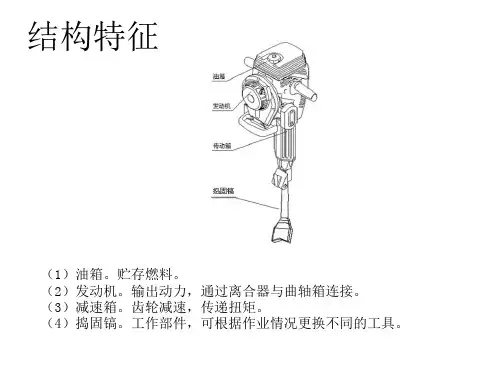
结构特征
(1)油箱。贮存燃料。 (2)发动机。输出动力,通过离合器与曲轴箱连接。 (3)减速箱。齿轮减速,传递扭矩。 (4)捣固镐。工作部件,可根据作业情况更换不同的工具。
tl-fc311a-3说明书

tl-fc311a-3说明书TL-FC311A-3是一款功能强大的光纤线缆剥皮工具,适用于剥离光纤线缆外层绝缘材料,以便进行进一步连接或焊接。
本文将为您提供关于TL-FC311A-3的相关参考内容,包括工作原理、使用方法、技术规格以及注意事项等。
工作原理:TL-FC311A-3采用精密切割刀片和可调节孔径设计,能够快速而准确地剥离光纤线缆的外层绝缘材料。
该工具先通过调节孔径来适应不同直径的光纤线缆,然后在剥离过程中使用切割刀片直接切割外层绝缘材料,最终将其完全剥离。
使用方法:1. 首先,将光纤线缆的外层绝缘材料放入TL-FC311A-3的可调节孔径中。
确保孔径与光纤线缆直径相匹配。
2. 确保TL-FC311A-3的切割刀片处于正确的位置,并固定好。
3. 握住TL-FC311A-3的手柄,将切割刀片放在光纤线缆的外层绝缘材料上,并轻轻向下压力,切割刀片将切割外层绝缘材料。
4. 继续旋转光纤线缆,使切割刀片将外层绝缘材料完全剥离。
技术规格:- 材质:高强度塑料- 颜色:黄色- 重量:约150克- 尺寸:约15×5×2.5厘米注意事项:1. 在使用TL-FC311A-3之前,确认切割刀片是否固定好,并调整好合适的孔径。
2. 使用时请注意保持手柄稳定,以免造成伤害。
3. 使用前请确保工具处于完好无损的状态,如有损坏请勿使用。
4. 在剥离光纤线缆的过程中,切割刀片可能会非常锋利,请注意安全使用。
5. 使用后请将TL-FC311A-3放置在安全地方,避免儿童触碰。
6. 请遵守光纤线缆的使用安全操作规范,以确保工作的安全进行。
总结:TL-FC311A-3是一款高效、可靠的光纤线缆剥皮工具,可以帮助用户精确地剥离光纤线缆的外层绝缘材料。
通过正确使用TL-FC311A-3,用户可以在光纤连接或焊接过程中提高效率和可靠性。
希望以上的内容对您了解TL-FC311A-3有所帮助。
遥控介绍F23系列

名称: F23-A+类别:发射器规格:尺寸:21.8*6.0*6.0厘米重量:约350公克系列: F23 系列简介:详细介绍: 产品性能指标* 6个按键(其中上/下为双速),1个开机键,1个急停* 低耗电量(使用两颗AA碱性电池平均使用寿命可达2个月)* 操作功能均可透鼺-23软件做设定(与win98/ME/2000/XP相容)* 操作距离可达100公尺* 发射及接收机均为内藏式天线(接收机可另行加装附件:被动天线)* 透过新的弹性化设计可自行组装及设定(DIY)* 多重安全保护设计的汉明码几32位元不重复识别码* 工作温度范围:-35℃至+80℃F23软件画面F-23遥控器可由PC软件设定多种按键功能,例如:普通、捺跳、开及关、寸动、相互抑制不相互抑制、加速延迟等多种不同控制功能;另外还有四种特殊模式之下按键功能设定,使遥控更具有弹性及适应各种不同类型之行车或机器设备使用。
F-23弹性化设计本工业用无线电遥控器之接点输出,可依照使用者实际需求自行规划设计。
无论是总电源(MAIN),共线(COM)或是继电器之常开/常闭接点都可自由跳接名称: F23-A++类别:发射器(耐用型)规格:尺寸:21.8*6.0*6.0厘米重量:约350公克系列: F23 系列简介:详细介绍:产品性能指标*8个单速按键,1个开机键,1个急停* 低耗电量(使用两颗AA碱性电池平均使用寿命可达2个月)* 操作功能均可透鼺-23软件做设定(与win98/ME/2000/XP相容)* 操作距离可达100公尺* 发射及接收机均为内藏式天线(接收机可另行加装附件:被动天线)* 透过新的弹性化设计可自行组装及设定(DIY)* 多重安全保护设计的汉明码几32位元不重复识别码* 工作温度范围:-35℃至+80℃F23软件画面F-23遥控器可由PC软件设定多种按键功能,例如:普通、捺跳、开及关、寸动、相互抑制不相互抑制、加速延迟等多种不同控制功能;另外还有四种特殊模式之下按键功能设定,使遥控更具有弹性及适应各种不同类型之行车或机器设备使用。
丽泽产品介绍(201508新)(1)
目录1. 金库网络门禁控制器 (3)1.1. DW-6831J/6832J/6834J-CP (3)2. 短信视频网络门禁控制器 (5)2.1. DW-6834D-CP (5)3. 网络双门互锁门禁控制器 (7)3.1. DW-6832AS-CP (7)4. 自助银行门禁控制器 (9)4.1. DW-6834Y-CP (9)5. 平安社区视频门禁控制器 (10)5.1. DW-6834C/6832C/6831C-CP (10)6. 网络门禁控制器 (11)6.1. DW-6831A/6832A/6834A-CP (11)7. 网络门禁控制器 (13)7.1. DW-6841A/6842A/6844A/6846A/6848A-CP (13)8. 网络门禁控制器 (15)8.1. DW-6814R-CP (15)9. 双门互锁控制器 (17)9.1. DW-2102AS-CP (17)10. 读卡器 (19)10.1. 读卡器-DW-100系列——DW-102M/102MK/108S/108C/108CK (19)10.2. 读卡器DW-106系列 (20)10.3. 读卡器DW-201系列 (21)10.4. 手机读卡器-------DW-202RM (22)10.5. 读卡器DW-203系列 (23)11. 发卡器 (24)11.1. 发卡器DW-100系列----DW-107 (24)12. 生物识别 (25)12.1. 半导体指纹仪——DW-FP1-L (25)12.2. TCP/IP半导体指纹仪——DW-FP3 (26)12.3. TCP/IP半导体指纹仪——DW-FP3-M (28)12.4. 光学指纹仪——DW-F11 (30)12.5. DW-F11-G (31)12.6. 人脸识别仪FC1 (32)12.7. 人脸指纹一体DW-FC1-PZ (34)12.8. 指纹静脉识别仪FV1 (35)12.9. 手持机 (37)12.10. 视频读卡一体机2240S (39)13. 丽安通停车场系统 (41)13.1. 停车场出入口管理控制器DW-C2104 (41)13.2. 停车场出入口管理控制器DW-C2115 (43)13.3. 道闸DW-C600 (44)13.4. 远距离读卡器206BT (45)13.5. 车牌识别C401T (46)13.6. 超声波车位引导C500系列 (48)14. 通道闸 (49)14.1. 三辊闸DW-TD1000GZ (49)14.2. 三辊闸DW-TD1001GZ (51)14.3. 翼闸DW-TD1000YZ (53)14.4. 翼闸DW-TD1001YZ (55)14.5. 摆闸DW-TD1000BZ (56)14.6. 摆闸DW-TD1001BZ (58)14.7. 全高转闸DW-TD1002QG (60)14.8. 全高转闸DW-TD1002QG (61)14.9. 平移门DW-TD1000PZ (63)15. 梯控系统 (65)15.1. IC卡电梯门禁控制器DW-TK2011M/TK2012/TK102M/TK102MK-CP (65)16. 消费机 (67)16.1. DW-3101M(台式) (67)16.2. DW-3101G (69)17. 巡更设备 (70)17.1. DW-XG300——蓝牙通讯座 (70)17.2. DW-XG5203——蓝牙巡更棒, (71)17.3. DW-XG100——巡更卡 (72)17.4. DW-XG5202/1——巡更棒 (73)18. 电锁 (74)18.1. 电锁——DW-601L/6280 (74)18.2. 灵性锁——LDS2 (75)18.3. 灵性锁——LX01 (76)1. 金库网络门禁控制器1.1. DW-6831J /6832J/ 6834J-CP针对银行标准设计的专用金库网络门禁控制器,远程与本地守库有机结合,防止内、外偷盗事件发生。
ic2300h中文说明书
ic2300h中文说明书
一、频率设定
开机后,按一下LCD下方的SCANV、MHZ钮,屏幕显示“14--,”用DIAL旋钮选择十位频率数,再按SCANV、MHZ确定选择个位频率值,再次按SCANV、MHZ用DIAL(大旋钮)直接选择小数位频率。
二、亚音设定
1、SETLOCK进入设定模式,按SET或者是MONI多次会出现“CT”“DT”这几个菜单,出现每一个菜单可以用DIAL旋转选择所需的亚音值,“CT”是模拟亚音,“DT”是数字亚音。
2、按其他的任意键退出设定模式。
3、按TENET--SCAN键多次直至出现一个小喇叭的符号(改变模拟亚音)或是一个大D符号(改变数字亚音)即可旋转大旋钮选择亚音。
三、频差设定
1、SETLOCK进入设定模式,按SET或者是MONI多次直到屏幕上角“±0.600”出现,此时就是频差的设定值,用DIAL旋转更改收发之间的差值即可。
2、按其他的任意键退出设定模式。
3、按住DUPLOW键,屏幕会出现“-”,说明频率是收高发低;再按住DUP键,会出现“+”,说明频率事发高收低,在按一下就取消收发异频,恢复常规直通频点。
数控切割控制系统F2000
阅读手册 .............................................................................................................................................. II 环境要求 .............................................................................................................................................. II 维护...................................................................................................................................................... II 高压电.................................................................................................................................................. II
1.5.1 F2100B/T 硬件配置 .............................................................................................................5 1.5.2 F2300A/B/T 硬件配置..........................................................................................................5 1.5.3 F2500A/B/T 硬件配置..........................................................................................................6 1.5.4 F2600/T 硬件配置 ................................................................................................................6
宝恒DKJ样本
TEL:022-27633338 FAX:022-27634764
三:工作原理及部件构成
DKJ、DKZ系列电动执行器是一个采用两相交流伺服电动机为原动力的位置伺服机构,其典型系统方块图如下图 所示:
DFD
CF
SD
J
WF
CF:位置定位器 SD:伺服电动机 J:减速器 DFD:电动操作器 WF:位置反馈单元
TEL:022-27633338 FAX:022-27634764
2
天津-宝恒
2:整体电子式电动执行器 整体电子式电动执行器属于引进技术,其主要特点是将位置定位器集成到电动执行器的内部。这样电动执行器就 可以直接接受4-20mA的控制信号,同时将位置信号反馈回控制室。这种控制方案简化了系统设计,节约整体仪表造价, 使系统的安装、调试变得简单方便。另外,由于位置定位器的集成技术属于引进国外的先进技术使得电动执行器的整 体可靠性大大提高。 整体电子式电动执行器与上位仪表配套使用时,如果需要通过仪表操作盘人工操作电动执行器,可以在上位仪 表与执行器之间增加DFQ型电动操作器以完成对执行机构的自动、手动转换,及手动的远方操作。 DFQ型操作器由转换开关、操作电位器、毫安指示表等元件组成。 整体式电动执行器的仪表基本配置见下图:
390 180 121 82 170 196 35 Φ14 Φ58 Φ20 C18×40 420 210 660 440 25 80 29
390 180 182 87 200 196 35 Φ14 Φ65 Φ30 C18×85 450 240 730 444 35 85 29