SCE PORTAL用户手册
ProPlex SceneSwitch 8用户手册说明书
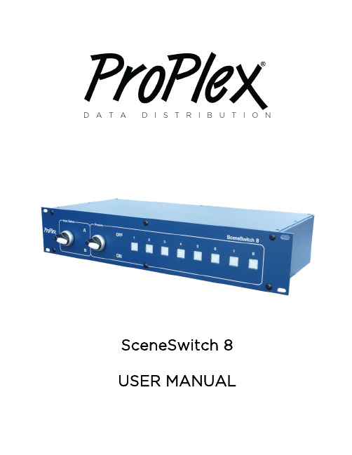
D A T A D I S T R I B U T I O NSceneSwitch 8USER MANUALProPlex SceneSwitch 8 User ManualEffective 11 June 2021© Copyright 2021, TMBAll rights reservedTMB authorizes its customers to download and print this electronically published manual for professional use only. TMB prohibits reproduction, modification or distribution of this document for any other purposes, without express written consent.Specifications are sub j ect to change without notice. The information in this document supersedes all previously supplied information before the effective date listed above. TMB has confidence in the accuracy of the document information herein but assumes no responsibility or liability for any loss occurring as a direct or indirect result of errors or exclusions whether by accident or any other cause.T ABLE OF C ONTENTS1.I NTRODUCTION (4)P RODUCT O VERVIEW (4)U NPACKING I NSTRUCTIONS (4)P OWER R EQUIREMENTS (4)S AFETY I NSTRUCTIONS (5)F USE R EPLACEMENT (5)P ANEL F RONT (6)P ANEL B ACK (6)A/B C ONNECTIONS (7)2.O PERATION (8)S WITCHING P RESETS M ODE O N (8)R ECORDING THE S CENES (P RESETS) (8)E RASE A LL P RESETS (9)L ED S TATUS I NDICATOR P OSITIONS (9)S WITCHING B ETWEEN I NPUTS A AND B (9)3.A PPENDIX (10)L IMITED W ARRANTY (10)R ETURN P ROCEDURE (10)T ECHNICAL S PECIFICATIONS (11)TMB24/7T ECHNICAL S UPPORT (11)1. IntroductionP RODUCT O VERVIEWSceneSwtich 8 is an 8-universe A/B switcher with built-in 8-scene playback. Features include: •Instantly switches between two DMX sources•Unique 8-scene, 8-universe playback feature instantly recalls 8 pre-recorded static scenes, individually or in combination•Rugged, oversize rotary analog switch for speed and reliability•Reliable, efficient console switching. Ideal for multiple act, multiple console shows. •Illuminated scene buttons for any show environment•PowerCon IN and THRUU NPACKING I NSTRUCTIONSUpon receipt of the unit, carefully unpack the carton and check the contents to ensure that all parts are present and in good condition. Notify the shipper immediately and retain packing material for inspection if any parts appear to be damaged from shipping or if the carton itself shows signs of mishandling. Save the carton and all packing materials. In the event that a unit must be returned to the factory, it is important that it unit be returned in the original factory box and packing.P OWER R EQUIREMENTSBefore powering the unit, make sure the line voltage is within the range of accepted voltages. This unit accommodates 100-240VAC, 50/60Hz. All units must be powered directly from a switched circuit and cannot be operated with a rheostat (variable resistor) or dimmer circuit, even if the rheostat or dimmer channel is used solely for a 0-100% switch.S AFETY I NSTRUCTIONS• Keep this User Guide for future reference. If unit is sold to another user, make sure they also receive this instruction booklet.• Ensure the unit is connected to proper voltage, and that line voltage is not higher than that stated on the device.• Make sure there are no flammable materials close to the unit while operating.• Always disconnect from the power source before servicing or fuse replacement. Always use the fuse specified in this manual..• Always use a safety cable when hanging unit overhead.• Maximum ambient temperature (Ta) is 40°C (104°F). Do not operate unit at temperatures above this rating.•In the event of a serious operating problem, stop using the unit immediately. Repairs must be carried out by trained, authroized personnel. Conact the nearest authorized technical assistance center. Only OEM spare parts should be used. • Do not connect the device to a dimmer pack.• Make sure power cord is never crimped or damaged.•Never disconnect power cord by pulling or tugging on the cord.Caution! There are no user serviceable parts inside the unit. Do not open the housing or attempt any repairs yourself. In the unlikely event your unit may require service, please contact your distributor.F USE R EPLACEMENTThe SceneSwitch uses a 1.0A, 250V barrel fuse, 5x20mm (0.2x0.8 in.). To replace fuse:1. With a screwdriver turn the fuse cap counter-clockwise to remove fuse cap with fuse.2. Replace fuse attached to fuse cap.3. Reinsert fuse cap with new fuse and tighten clockwisePlease read these instructions carefully. This user guide contains important information about the installation, usage and maintenance of this product.Disconnect the power cord before replacing a fuse and always replace with the appropriate fuse.P ANEL F RONT: P ANEL B ACK:S CENE S WITCH 8A/B C ONNECTIONSTwo lighting consoles are connected to SceneSwitch. Main console connected to DMX input A; backup console connected to DMX input B.Example 1: The A/B rotary switch is turned to input A (main console).Example 2: The A/B switch is turned to input B (backup console).NOTE: If the unit loses power, DMX input group A is automatically selected, a convenient backup solution in larger systems.NOTE: Outputs are not optically isolated. SceneSwitch 8 is not intended for use as a repeater.2. OperationS WITCHING P RESETS M ODE ONTo switch between presets mode ON/ OFF, just turn the switch and the LED indicator willactivate if presets are ON.Example shown: Preset 1 active; presets 2-8 have scenes stored but inactive.R ECORDING THE S CENES (P RESETS)SceneSwitch has 8 static memory buttons (presets, 1-8). These static scenes contain asnapshot of all DMX channel values in all 8 possible input universes at the time they were captured.To record one of the 8 static memories, choose from which DMX input the memories will be recorded (A or B DMX input) and switch the input selector to the chosen input (A or B position). Once this is done, follow this sequence:1)Use the lighting console to set the necessary DMX channel levels (create the desired lightingpreset to be recorded on SceneSwitch preset button).2)Perform a visual check making sure the preset is as you want it to be (necessary beam angle,brightness and color levels).3)Press and hold the chosen memory button for 5 seconds or longer.4)When LED status indicators start to blink, release the memory button.5)When the memory is recorded the LED status indicator of the button will be illuminated at20% intensity.NOTE: Multiple memories can be activated at the same time – they will be merged using HTP (Highest Takes Precedence) protocol.To activate any of the pre-programmed presets, press the desired preset button for less than one second. The active preset button will glow at 100% intensity. Several presets may be activated simultaneously. To turn off the preset, press the preset button. The LED status indicator will switch to 20% intensity when the preset is inactive.E RASE A LL P RESETSTo delete all information in all of the memory buttons:Press and hold buttons No. 1 and No. 8 until LED status indicators blink for a short time. All memories are erased and all LED status indicators are turned off.LED S TATUS I NDICATOR P OSITIONSSceneSwitch 8 preset buttons have 3 indicating LED brightness positions:•OFF – Memory button is "empty" (no recorded presets)•Turned on at 20% -- Preset is recorded•Turned on at 100% -- Preset is activeS WITCHING B ETWEEN I NPUTS A AND BTo switch between A and B inputs, turn the switch to either A or B. LED indicators will activate on either A or B to indicate which input is active.NOTE: Preset switch must be turned OFF when using DMX inputs as the DMX signal source.3. AppendixL IMITED W ARRANTYProPlex Data Distribution Devices are warranted by TMB against defective materials or workmanship for a period of two (2) years from the date of original sale by TMB.TMB’s warranty shall be restricted to the repair or replacement of any part that proves to be defective and for which a claim is submitted to TMB before the expiration of the applicable warranty periods.This Limited Warranty is void if the defects of the Product are the result of:•Opening the casing, repair, or adjustment by anyone other than TMB or persons specifically authorized by TMB•Accident, physical abuse, mishandling, or misapplication of the product.•Damage due to lightning, earthquake, flood, terrorism, war, or act of God.TMB will not assume responsibility for any labor expended, or materials used, to replace and/or repair the Product without TMB’s prior written authorization. Any repair of the Product in the field, and any associated labor charges, must be authorized in advance by TMB. Freight costs on warranty repairs are split 50/50: Customer pays to ship defective product to TMB; TMB pays to ship repaired product, ground freight, back to Customer.This warranty does not cover consequential damages or costs of any kind.A Return Merchandise Authorization (RMA) Number must be obtained from TMB prior to return of any defective merchandise for warranty or non-warranty repair. For all repairs please contact TMB Tech Support Repair using the contact information below or email***************************.US UK527 Park Ave. 21 Armstrong WaySan Fernando, CA 91340 Southall, UB2 4SD EnglandTel: +1 818.899.8818 Tel: +44 (0)20.8574.9700Fax: +1 818.899.8813 Fax: +44 (0)20.8574.9701******************************** R ETURN P ROCEDUREPlease send returned merchandise prepaid and in the original packing. Freight call tags will not be issued for shipping the product to TMB, but TMB will pay the freight for return to the customer. Clearly label package with a Return Merchandise Authorization Number (RMA #). Products returned without an RMA # will delay service. Please contact TMB and request an RMA # prior to shipping the unit. Be prepared to provide the model number, serial number, and a brief description of the cause for the return. Be sure to properly pack the unit; any shipping damage resulting from inadequate packaging is the customer’s responsibility. TMB reserves the right to use its own discretion to repair or replace product(s). Proper UPS packing or double-boxing will better ensure product integrity when shipped.Note: If you are given an RMA #, please include the following information on a piece of paper inside the box:1) Your name2) Your address3) Your phone number4) The RMA #5) A brief description of the symptomsS CENE S WITCH 8 – T ECHNICAL S PECIFICATIONSWEIGHT&DIMENSIONSW IDTH......................................................................................................................... 19 IN /483 MMD EPTH ......................................................................................................................... 8.1IN /205 MMH EIGHT......................................................................................................................... 3.5 IN /90 MMW EIGHT..................................................................................................................8.05 LB /3.65 KGEIA R ACK U NITS...................................................................................................................... 19”2U POWERO PERATING V OLTAGE................................................................................. 100-240V, 50-60HzP OWER C ONSUMPTION..................................................................................................... 10W MAX. THERMALO PERATING TEMPERATURE...................................................................................... -20 TO +40°CC OOLING ...................................................................................................................... Convection CONTROL/PROGRAMMINGDMX I NPUTS........................................................................................ 2 X 8, LOCKING 5-PIN XLR,DMX OUTPUTS............................................................................................ 8, LOCKING 5-PIN XLRM EMORY L OCATIONS (8)WARRANTY INFORMATIONW ARRANTY......................................................................................... 2-YEAR LIMITED WARRANTY TMB24/7T ECHNICAL S UPPORTUS/Canada: +1 818.794.1286Toll Free: 1 877.862.3833 (877.TMB.DUDE)UK: +44 (0)20.8574.9739Toll Free: 0800.652.5418e-mail:*******************CONTACT INFORMATIONLOS ANGELES HEADQUARTERS 527 Park Avenue | San Fernando, CA 91340, USATel: +1 818.899.8818 | Fax: +1 818.899.8813*************TMB 24/7 TECH SUPPORTUS/Canada: +1.818.794.1286 Toll Free: 1.877.862.3833 (1.877.TMB.DUDE)UK: +44 (0)20.8574.9739Toll Free: 0800.652.5418*******************LOS ANGELES +1 818.899.8818LONDON +44 (0)20.8574.9700NEW YORK +1 201.896.8600BEIJING +86 10.8492.1587CANADA +1 519.538.0888A full service company providing technicalsupport, customer service, and follow-up.Providing p roducts and services for the industrial, entertainment, installation, defense, broadcast, research, telecommunications, and signage industries.Servicing the global market from offices in Los Angeles, London, New York, Toronto, and Beijing.。
丝琴实验室步进电机参考设计包用户指南说明书

Rev. 0.1 5/06Copyright © 2006 by Silicon LaboratoriesSTEPPER-MOTOR-RD1. Kit ContentsThe Stepper Motor Reference Design Kit contains the following items:⏹Stepper Motor Reference Design Board ⏹Stepper Motor⏹Universal AC to DC Power Adapter ⏹USB Debug Adapter ⏹USB Cable ⏹Serial Cable⏹Reference Design Kit Tools & Documentation CD2. Kit OverviewThis reference design demonstrates a high-performance stepper motor system using the C8051F300/1. The reference design provides for both stand-alone demo operation and UART control. The reference design may also be used as a platform for stepper motor code development.This User's Guide provides a step-by-step guide for getting your system up and running. Refer to the application note “AN155: Stepper Motor Reference Design“ for complete documentation of the Stepper Motor Reference Design.Figure 1. Stepper Motor Reference Design BoardSTEPPER-MOTOR-RD3. Stepper Motor Reference Design DemonstrationThe Stepper Motor Reference Design includes everything you need to set up a stepper motor demonstration. Connect the stepper motor to the stepper motor control board following the wiring chart for the 42BYG205 motor as shown in Table1.Table 1. GBM 42BY201 Stepper Motor Wiring DiagramColor Namered A+yellow Acblue A–green B+orange Bcbrown B–Connect the universal ac/dc power adaptor to the dc supply (P1) on the Stepper Motor Reference Design Board. Press the Function (FUNC) button on the Stepper Motor Reference Design Board. The motor will turn in one direction. Notice that the motor accelerates smoothly up to the maximum speed, moves at a constant speed, and then decelerates smoothly to a standstill. Press the function button again and the motor will turn the other direction.Figure 2. Stepper Motor Reference Design Demonstration SetupSTEPPER-MOTOR-RD 4. HyperTerminal DemonstrationStart with the Demo Setup above and add an RS-232 cable connection to your computer as shown in Figure3. The RS-232 connection is used with a terminal program to provide a basic terminal interface for the stepper motor. If your PC has USB and does not have a serial port, you may use the Silicon Laboratories CP2102 EK to provide a virtual COM port connection.Figure 3. Stepper Motor Reference Design Terminal SetupOpen the HyperTerminal application. The HyperTerminal program may be launched on most Windows XP systems from the Start Menu:Start→Programs→Accessories→Communications→HyperTerminalEnter any name into the "Connection Description" dialog box is shown in Figure 4. In the "Connect To" dialog box, choose the COM port corresponding to the Serial connection on your PC. In the Port Settings dialog box select 57600 baud and no flow control. Use the default settings of 8 data bits, no parity, and one stop bit.Figure 4. Setting Up HyperTerminalSTEPPER-MOTOR-RDPush the Reset button on the Stepper Motor Reference Design Board. When reset, the Stepper Motor Reference Design sends a ">" prompt character to the terminal. If you do not get a prompt character, check your port settings,cable connections, and make sure the Stepper Motor Reference Design Board is powered.The Stepper Motor Reference Design command line provides some basic terminal commands to display motor status, change position, and change acceleration. Typing an “s” character immediately displays the motor status.Typing a "p" followed by a number and a return moves the motor to the desired position. See “AN155: Stepper Motor Reference Design“ for a detailed description of the command line interface.Figure 5. Stepper Motor Command LineSTEPPER-MOTOR-RD 5. Development Tool InstallationInstall the Reference Design Kit Tools from the Reference Design Kit Tools & Documentation CD. This installs the Silicon Laboratories IDE and the 2k code size limited version of the Keil Compiler.Figure 6. Install Development ToolsSTEPPER-MOTOR-RD6. Development Setup using the USB Debug AdapterThe Stepper Motor Reference Design includes everything you need to develop your own stepper motor control firmware using the Silicon Laboratories C8051F300/1 MCU. The Stepper Motor reference design code may be used as a starting point for your own code development.Connect the Stepper Motor, ac/dc power adapter, and serial cable if you have not done so already. Refer to the stepper motor wiring Table1 on page2 for the stepper motor connections. Connect the USB Debug Adapter ribbon cable to the 10-pin Debug connector on the Stepper Motor Reference Design Board. Connect the USB Debug Adapter to your PC using the supplied USB cable as shown in Figure7.Figure 7. Development Setup using the USB Debug AdapterSTEPPER-MOTOR-RD 7. Stepper Motor ProjectThe source code for the Stepper Motor Reference design is installed from the CD onto your hard drive in the following default location:C:\SiLabs\MCU\Stepper_Motor_RD\firmware\The software for AN155 is also available as a zip file on the CD or from the Silicon Laboratories website.To create a stepper motor project, complete the following steps:unch the Silicon Laboratories IDE from the Start menu.2.Select “Add Files to Project” from the Project menu.3.Browse to the source code location listed above, and open the file stepper.c.4.Double click on Stepper.c in the Project Workspace pane to open.5.Select “Rebuild All” from the project menu or click on the “Rebuild All” button. (The IDE will compile and link thestepper.c file as shown in Figure8.)6.Select “Connection Options” from the Options menu.7.Make sure the USB Debug Adapter is selected and the Debug Interface is using the C2 connection.8.Select “Connect” from the Debug menu, or click on the “Connect” button in the tool bar.The Status Bar should display Target:C8051F301 to indicate the IDE is connected to the MCU on the Stepper Motor Reference Design Board. Refer to the application note AN155 for additional information on the stepper motor code.Figure 8. Stepper Motor ProjectSTEPPER-MOTOR-RD8. Related Documents⏹Stepper Motor Reference Design Quick Start Guide⏹AN155: Stepper Motor Reference DesignSoft copies of this document and the ones listed above are included on the Reference Design Kit Tools & Documentation CD. Click on Browse Documents to locate them or explore the CD and locate the User’s Guides and Application Notes in the Documents folder.The latest versions of the documentation and software can also be downloaded from the Silicon Laboratories website .DisclaimerSilicon Laboratories intends to provide customers with the latest, accurate, and in-depth documentation of all peripherals and modules available for system and software implementers using or intending to use the Silicon Laboratories products. Characterization data, available modules and peripherals, memory sizes and memory addresses refer to each specific device, and "Typical" parameters provided can and do vary in different applications. Application examples described herein are for illustrative purposes only. Silicon Laboratories reserves the right to make changes without further notice and limitation to product information, specifications, and descriptions herein, and does not give warranties as to the accuracy or completeness of the included information. Silicon Laboratories shall have no liability for the consequences of use of the information supplied herein. This document does not imply or express copyright licenses granted hereunder to design or fabricate any integrated circuits. The products must not be used within any Life Support System without the specific written consent of Silicon Laboratories. A "Life Support System" is any product or system intended to support or sustain life and/or health, which, if it fails, can be reasonably expected to result in significant personal injury or death. Silicon Laboratories products are generally not intended for military applications. Silicon Laboratories products shall under no circumstances be used in weapons of mass destruction including (but not limited to) nuclear, biological or chemical weapons, or missiles capable of delivering such weapons.Trademark InformationSilicon Laboratories Inc., Silicon Laboratories, Silicon Labs, SiLabs and the Silicon Labs logo, CMEMS®, EFM, EFM32, EFR, Energy Micro, Energy Micro logo and combinations thereof, "the world’s most energy friendly microcontrollers", Ember®, EZLink®, EZMac®, EZRadio®, EZRadioPRO®, DSPLL®, ISOmodem ®, Precision32®, ProSLIC®, SiPHY®, USBXpress® and others are trademarks or registered trademarks of Silicon Laboratories Inc. ARM, CORTEX, Cortex-M3 and THUMB are trademarks or registered trademarks of ARM Holdings. Keil is a registered trademark of ARM Limited. All other products or brand names mentioned herein are trademarks of their respective holders.Silicon Laboratories Inc.400 West Cesar Chavez Austin, TX 78701USAIoT Portfolio /IoTSW/HW/simplicityQuality/qualitySupport and Community。
安第斯供应商门户用户手册说明书

Para acceder a Portal podrá hacerlo por las siguientes vías:∙Acceso directo: https:///irj/portal∙Ingresando desde el link que se encuentra en la página de internet de Andina Argentina /?localizacion=arPortal deProveedoresUna vez que accedió a la pagina, deberá autenticarse en el Portal con su ID (número de proveedor) y contraseña.El ID y su clave de acceso fueron informados en el correo enviado por******************************,el ID es el número de proveedor y la clave es andina.01El sistema solicita el cambio de la contraseña, la cual debe cumplir con los requisitos de seguridad establecidos por la empresa:∙Puede usar de 6 a 8 caracteres sin emplear caracter es especiales (¡,”, ¿ o espacios en blanco).∙Se diferencian mayúsculas y minúsculas.∙No puede repetir una contraseña utilizada las ultimas 6 veces.∙La contraseña caduca cada 30 días.En clave de acceso anterior repita la clave enviadaEn clave acceso nueva coloque la clave deseadaEn confirmar clv. Acceso vuelva a repetir la clave deseadaAcceso Portal Andina ArgentinaSi el Proveedor en el futuro desea habilitar o deshabilitar su acceso al Portal, podrá hacerlo solicitándolo vía email al Departamento de Compras Andina Argentina.Además la empresa podrá interrumpir temporal o definitivamente la clave de acceso de cualquier proveedor por los motivos que Andina Argentina considere necesarios y sin previo aviso.En caso que no recuerde su contraseña de acceso, podrá obtener una nueva clave ingresando a la opción “soporte”, continuando los siguientes pasos.Importante:la nueva contraseña se enviara a la dirección de mail registrada en Andina Argentina.a. Ingresar a Soporteb. Deberá completar los siguientes datos:∙Identificación usuario: numero de proveedor.∙Correo electrónico: su mail registrado en Andina Argentina.c. Luego ir a Enviar.Importante:los datos cargados deben coincidir con los registrados en Andina Argentina.Caso contrario no podrá continuar con la operación y deberá solicitar la nueva clave vía correo electrónico a los administradores en el sector de compras: ******************************Ingresando al menú de “Gestión Facturas”usted podrá acceder a las siguientes opciones:Facturas pagas:son todos aquellos comprobantes que han sido cancelado por un pago emitido por la empresa (la fecha de pago indica la fecha que fue emitido el pago en los registros contables). Se podrá filtrar las facturas según la fecha de pago, a partir de una fecha tope mínima definida por la empresa y dentro de un rango de fechas seleccionadas.Facturas pendientes:son aquellos comprobantes que han sido registrado en los sistemas de la empresa y que a la fecha no ha sido emitido el pago correspondiente. Permite al proveedor consultar las facturas pendientes de pago a partir de una fecha tope mínima definida por la empresa.Ver factura: permite al proveedor consultar las facturas generadas que están pagas o pendientes, a partir de una fecha tope mínima definida por la empresa.a. Facturas PagasPodrá ver las facturas pagas y filtrar la búsqueda por fecha de pago del documento: Importante: La fecha tope máxima a consultar estará definida por la empresa (fecha del día menos uno). El detalle de los pagos aparecerá al día siguiente de realizada la transferencia bancaria y/o emisión del cheque.Una vez ingresado el filtro, presionar Buscar. Se desplegará la información de la siguiente manera:En la tabla en la izquierda, se puede visualizar las facturas agrupadas por el documento de compensación correspondiente. Al final por cada documento de compensación se muestra el total de los importes (celdas verdes y texto resaltado).Al seleccionar un documento de compensación o un registro, se mostrará información adicional del pago en la tabla de la derecha. Aquí se observara la fecha de pago,númerode cheque, vía de pago eimporte neto (importe total de facturas menos retenciones impositivas) correspondiente a ese documento de compensación.Las últimas columnas permiten descargar el certificado de retenciones y la remesa de pago en formato PDF.El sistema también ofrece la posibilidad de exportar la información en pantalla a un archivo Excel. Simplemente presionar sobre el link Exportar a Excel en la parte superior izquierda y obtendrá el reporte.b. Facturas PendientesAl ingresar accede a un listado de facturas pendientes de pago con la información más relevante.Se podrá visualizar datos a partir de la fecha tope definida por la empresa.Además posicionándose en el link Exportar a Excel se envía la información a un archivo Excel.c. Ver FacturasPodrá acceder a datos de una factura en particular, sea esta paga o pendiente . Para ello deberá completar el siguiente filtro con el número de factura completo:Al presionar buscar , el sistema busca la factura y muestra el detalle debajo:En el caso de que fuera una factura paga semostraráel documentode compensación asociado. Si sepresiona sobreel link del documento de compensación , se podrá visualizar el menú de Facturas Pagas ofreciendo el detalle del documento de compensación seleccionado.a. IMPORTANTE: ante cualquier inconveniente con el Portal de Proveedores:enviar un mail con la imagen de la pantalla de error a ****************************** óenviar un“SMS” al N°3517543000 y nos contactaremos en un plazo máximo de 48 hs para resolver el problema. En el mensaje deberá mencionar:- N° de Proveedor / Usuario Portal- N° de Teléfono de contacto- Persona de contacto (Nombre y Apellido)- Horario de atención (Ej: 9:00 a 18:00 hs)- En el caso de que sea correo, print de pantalla con el error.b. Si es la primera vez que ingresa a la página puede darle un error de certificadode seguridad; haga clic en Vaya a este sitio web (no recomendado)c. Una vez que accedió al Portal a través de “Acceso Portal Andina Argentina”,deberá ingresar con su ID (número de proveedor) y contraseña.Recomendamos copiar la clave desde el mail que le enviamos y pegarla en clave de acceso.Se le solicitara el cambio de claveEn clave de acceso anterior repita la clave enviada por Andina ArgentinaEn clave acceso nueva coloque la clave deseadaEn confirmar clv. Acceso vuelva a repetir la clave deseadad. Luego de haber ingresado colocando su Usuario y Contraseña puede aparecerel siguiente mensaje de advertencia.Para quitar este mensaje debe moverse a la opción “Gestión Facturas”.e. De acuerdo al tipo y versión de Explorador de Internet que utilice para acceder ala página web, puede aparecer el siguiente mensaje de error:Para solucionarlo se deberá utilizar una versión del Explorador compatiblecon el Portal de Proveedores:Interner Explorer: versión 8 o anteriores.Si cuenta con Internet Explorer 9 o posterior podrá cambiar a la versión 8presionando la tecla F12, donde se desplegara una ventana y en lasolapa Modo de explorador: IE9, seleccionar Internet Explorer 8.Internet Explorer 8 Mozilla Firefox: versión 2.0 en adelante, para los Sistemas OperativosWindows XP / Vista, Linux y MacOs.Google Chrome: versión N° 28 en adelante.f. Problema en “Facturas Pagas” al abrir los archivos PDF de los certificados deretención y/o remesa de pago:No se abre el documento o se abre una pantalla en blanco:- Debe descargar/instalar la última versión disponible del programa “Adobe Reader”(programa gratuito), e intentar nuevamente.- En el caso de certificados de retenciones verificar que en el documento de pago consultado se hayan practicado retenciones impositivas, esdecir, que no sean igual a $ 0.。
Portal集成-开发手册

前言
本手册主要从Portal门户集成其他产品(包括第三方产品)涉及到单点登录、消息待办两个重要方面入手,详细介绍单点登录、消息待办的实现方案、开发操作步骤,同时给出典型系统集成的示例。
getLoginHelper().processLogin(userVO);
String serverUrl = ServerInfoHelper.getServerUrl();
url = serverUrl +"/portal/auth/"+ aKey;
2、令牌使用说明:第三方系访问的URL则为"/portal/auth/"后加上令牌号,如:http://localhost/portal/auth/23sqa33fdaf
第三章列举了门户常用的一些扩展功能点,以供读者参考。
接下来就详细介绍Portal门户与用友产品、其它第三方产品如何实现单点、待办集成的开发配置过程及其实现机制。
第一章
UapPortal的单点登录基本思路如下:使用数据库来存储各应用系统的访问凭证并关联Portal用户,在Portal登录后通过登录的Portal用户自动找到该应用系统的凭证直接进入各应用系统(每个应用系统一个portlet)。
Map<String, String> extMap =newHashMap<String, String>();
extMap.put(MAXWIN,"N");
SOLIDWORKS Customer Portal Quick Reference说明书

Logging Into the Customer Portal•In an internet browser session navigate to •Click the menu icon in the upper right corner•Select SW Customer Portal from the dropdown menu•You will be redirected to the SOLIDWORKS Customer Portal•Enter your email address•Enter your SOLIDWORKS ID password•Click the Log In buttonLocked Features•Register My Products•3D Content Central•API Examples•System Requirements•Hardware and Graphics•Registration and Activation•Admin Guides•Forms,•User Groups•SOLIDWORKS Express Newsletter•3DExperience World•CertificationIf you do not have a SOLIDWORKS ID, please see the Creating a SOLIDWORKS ID Quick Reference Guide The SOLIDWORKS Customer Portal requires a product on current subscription to access the full Customer Portal features. The limited Customer Portal features include:Downloads and Updates•Navigate to the Download section of the customer portal home page•Click the Downloads and Updates link•Select the software and version to download•Download your software •Navigate to the My Support section of the customer portal home page•Click the Register My Products link•Enter your Serial Number in the Serial Number text box•Click the Next button•Select the CURRENT version of your software•Click the OK button•Click the Next button•You will receive a confirmation of your Serial Number registration•Click the Next button•Your locks will no longer appear and you will have full access to theSOLIDWORKS Customer PortalRegistering Your Product。
西华升腾ERP操作手册

现代企业制造执行系统EX-MES 使用手册目录产品设计管理 0【1】产品结构 0【1.1】业务说明 0【1。
2】界面说明 0【1.3】功能介绍 (1)【1.4】操作说明 (2)【2】产品工艺 (4)【2.1】业务说明 (4)【2.2】界面说明 (5)【2.3】操作说明 (6)【3】产品基础资料维护 (6)【3.1】自制零件、产品信息维护 (6)【3。
2】外购原料、物资信息维护 (7)【3。
3】生产工艺基础信息维护 (8)【3。
4】计量单位维护 (9)【3。
5】产品结构导入 (9)【3。
6】产品工艺导入 (10)系统权限管理 (11)【1】操作员及权限设置 (11)【1.1】权限说明 (11)【1。
2】操作说明 (13)【2】部门管理组设置 (14)【3】维护职务级别 (15)【4】个人信息维护 (15)【5】系统参数设置 (16)【6】用户密码修改 (16)【7】领料用途维护 (16)【8】删除多余编码 (17)【9】操作日志管理 (17)【10】反算加工时间 (18)【11】公司信息维护 (18)【12】区域维护 (18)【13】流程审批管理 (19)【14】上传最新版本 (19)【15】PDM数据接口 (20)【16】外接ERP数据接口 (20)生产过程管理 (21)【1】生产计划管理 (21)【1。
1】业务说明 (21)【1。
2】业务流程图 (21)【1。
3】操作手册 (21)【1。
3。
1】生产计划建立 (21)【1。
3.2】生产计划分解 (23)【1。
3。
3】生产计划下达 (24)【1.4】注意事项 (24)【2】制造执行系统 (24)【2.1】业务说明 (24)【2.2】业务流程图 (25)【2.3】操作手册 (25)【2。
3.1】车间生产计划下达 (25)【2。
3。
2】车间班组设置 (29)【2。
3。
3】车间物资退换货管理 (30)【2.3。
4】组件/成品拆分 (31)【2.3。
5】车间完工汇报 (31)【2。
Microsoft Azure Stack 许可指南(终端用户)说明书
<Placeholder cover – we will adjust> Microsoft Azure StackLicensing Guide(end customers)August 20173 3 6 6 8How Azure Stack is purchasedThere are two ways to purchase Azure Stack:1.Purchase Azure Stack services via your own EA2.Purchase Azure Stack services from a service providerThis document provides licensing guidance for running the Azure Stack within your own enterprise. If you purchase Azure Stack services from a service provider, the provider will set the pricing and terms of use and offer support.Azure Stack is sold as an integrated system, meaning that software comes installed on prescribed hardware. A complete Azure Stack system is comprised of hardware, software, and support.Hardware: Hardware is purchased directly from the hardware vendor. A complete list of Azure Stack hardware partners can be found on the Azure Stack product page. If you are purchasing Azure Stack from a service provider, you may not need to purchase your own hardware.Software: You may purchase Azure Stack services via your Microsoft Enterprise Agreement (EA) or from a service provider. This document describes the model for purchasing Azure Stack via Microsoft EA only. When purchasing Azure Stack from a service provider, the service provider will set the terms and prices for the services.Support: If you purchase Azure Stack services from a service provider, your provider will provide support. If you purchase Azure Stack services via your Microsoft EA, support comes in two parts—hardware support and software support.•Hardware support is contracted directly with the hardware partners.•Software support is contracted directly with Microsoft. If you already have software support from Microsoft (Azure or Premier support plans), those contracts cover Azure Stack softwaresupport and no additional contracts or fees are needed. While support is with the hardwarepartner and Microsoft, our integrated support experience provides coordinated escalation and resolution, so you get a consistent support experience no matter who you call first. Azure Stack software–packaging and pricingThere are three layers to Azure Stack software: the cloud infrastructure that powers the system, the services running on the system, and portal capabilities. Only services running on the Azure Stack are billed. Services can be licensed in one of two ways as shown in Table 1--a pay-as-you-use (consumption-based) model and a capacity model.Table 1: Licensing ModelsPay-as-you-useThe pay-as-you-use model has no up-front fees and you pay only when you use a service, as shown in Table 2. This model offers a continuous transaction experience with Azure. Usage for each service is metered and transmitted to Microsoft Azure commerce, where the information is integrated and billed with your Azure usage.There is no initial deployment fee for pay-as-you use. Additionally, you are not charged for the virtual machines and software required to power the Azure Stack infrastructure. This means that Cloud Infrastructure, Management, Security, and Identity Services, as well as Networking and Service Fabric are not charged. The following describes the units of metering for the services available on Azure Stack at general availability. All services are entirely stand-alone. For example, when you run App Service, you are only spinning App Service meters.Table 2. Azure Stack Pay-as-You-Use Metering UnitsUp-Front Licensing Azure Stack initial deployment n/a – no upfront feesConsumption-Based Fees Cloud infrastructure; Management, Security, andIdentity; Networking; Service Fabricn/a – includedVirtual Machines: Base VM $/VCPU/minVirtual Machines: with Windows Server $/VCPU/minBlog Storage Service $/GB (no transaction fee) Tables and Queues Service $/GB (no transaction fee) Azure App Service $/VCPU/minTo run Windows Server virtual machines, you have the option of either using the native meters within Azure Stack or deploying existing Windows Server licenses in conjunction with the Azure Stack Base VM hourly meters. To run SQL Server virtual machines, you may deploy existing licenses in conjunction with Windows virtual machines. Details for how existing licenses work in conjunction with Azure Stack can be found in the “Using existing software” section of this document.Azure Stack pay-as-you-use services are available in EA and are sold in the same way as Azure services. This means Azure Stack is acquired via a monetary commit SKU on your Azure or SCE enrollment. You can use the same agreement, pool of monetary commit, and subscription IDs for your Azure and Azure Stack services. If you have an existing Azure agreement, you don’t need any additional agreemen ts or monetary commitment purchases—you need only enter your subscription ID when you install the system. Your Azure Stack usage will be metered and integrated into one bill with your Azure usage.Capacity ModelThe capacity model offers a more traditional licensing model for disconnected scenarios, as shown in Table 3. An annual subscription fee licenses all the physical cores on your Azure Stack. The capacity model is available in an App Service package or an IaaS package. The App Service package includes all the services on the IaaS package, plus Azure App Service (including Web, Mobile, Logic Apps, and Functions).Table 3. Azure Stack Capacity Model—Licensing Packages$/physical core/year$/physical core/yearAzure App ServiceAzure StorageBase Virtual MachineWindows VirtualBYO License BYO LicenseMachineSQL Server VirtualBYO License BYO LicenseMachineYou need existing Windows Server or SQL Server licenses to run Windows Server and SQL Server virtual machines on the capacity model. Details on how existing licensing works in conjunction with Azure Stack are discussed in “Using existing software” section of this document.The capacity model is available in EA only and can be ordered via standard Volume Licensing channels. The capacity model will not have integrated billing with Azure and Azure monetary commitment cannot be applied to the capacity model.Azure Stack supportAzure Stack support is a consistent, integrated, hybrid support experience that covers the full system lifecycle. To fully support your Azure Stack system, you need two support instruments—one with Microsoft for cloud services support and one with your hardware provider for system support. Our integrated support experience provides coordinated escalation and resolution, so you get a consistent support experience no matter who you call first. If you already have Premier, Azure, or Partner support with Microsoft, your Azure Stack software support is included.Although support is purchased in separate components, Microsoft and the hardware providers have partnered to create a unified support experience. You need only make one call to the vendor of your choice (Microsoft or hardware partner) for any Azure Stack issue. That vendor will help you diagnose the source of the issue and route your question accordingly.Using existing software with Azure StackCustomers may use existing software licenses (e.g., Windows Server, SQL Server, Marketplace services) in conjunction with Azure Stack. Azure Stack is treated like on-premises hardware for purposes oflicensing existing software. Customers must comply with all product licensing terms under which the software is acquired. When other software is used in conjunction with Azure Stack, the fee structure is:Licensing fees for the software (paid to the software vendor) + virtual machines consumed to run the serviceGuidelines for how Microsoft Windows Server and SQL Server licensing are applied to Azure Stack systems are discussed in the following sections.Windows Server licensingWhen deploying Windows Server virtual machines on Azure Stack, you may use existing Windows Server licenses as an alternative to the native hourly Windows Server meters in the pay-as-you-use model. Windows Server licenses acquired apart from Azure Stack are subject to terms and conditions stated in the Microsoft Product Terms.What follows are some guidelines for how the licensing terms and conditions can be applied when existing Window Server licenses are used with Azure Stack:1.Number of licenses required for Windows Server used with Azure StackTo comply with Windows Server licensing, all cores in an Azure Stack region must be covered, just like when licensing Hyper-V. Furthermore, all cores must be covered with the same edition of license (all Datacenter or all Standard), since the virtual machine may be sitting anywhere on the Azure Stack. We recommend Windows Server Datacenter for Azure Stack, since weanticipate your workloads will be heavily virtualized. You can use EA, Open, or Select PlusWindows Server licenses. Customers using volume licensing licenses must also have sufficientCALs to cover the use case. Since Azure Stack is on your own hardware, you do not need Azure Hybrid Use Benefit (AHUB) rights to use Windows Server in conjunction with Azure Stack.2.AHUB with Azure StackAzure Stack is considered on-premises hardware for licensing purposes. As such, you do notneed AHUB to use existing Windows Server licenses in conjunction with dedicated Azure Stack environments. Furthermore, the AHUB benefit does not extend to bringing Windows Server EA licenses to hosted, multi-tenant environments; you may not bring Windows Server EA licenses to such environments.SQL Server licensingSQL Server virtual machines can be deployed on Azure Stack by using separately acquired SQL Server licenses in conjunction with Windows virtual machines. SQL Server licenses acquired outside Azure Stack are subject to Microsoft Product Terms.What follows are some guidelines that illustrate how licensing terms and conditions are applied when existing SQL Server licenses are used with Azure Stack:1.Number of core licenses required for SQL Server used with Azure StackSQL Server may be licensed either by physical cores or by virtual machines. If licensing byphysical cores, you must license the entire Azure Stack region1. If licensing by virtual machines, you only need enough licenses to cover the virtual machines using SQL Server (subject to aminimum of 4 per virtual machine). If licensing by virtual machines, you may separately allocate SQL Server Enterprise and Standard edition licenses by virtual machine. Since Azure Stack is the customer’s own hardware, you do not need License Mobility when using SQL Server under EA on your own Azure Stack hardware.2.License MobilityAzure Stack is considered on-premises hardware for licensing purposes. As such, you do notneed License Mobility to use SQL Server licenses in dedicated Azure Stack environments. You will, however, need License Mobility if you bring your own SQL Server EA licenses to a service provider’s multi-tenant hosted environment. In that situation, you must also ensure your service provider is an authorized License Mobility provider.Example scenariosThe following figures and text illustrate a few examples for how services are licensed on Azure Stack, particularly focused on contrasting the licensing for pure Azure Stack meters with scenarios where on-premises licenses are used in conjunction with Azure Stack.If using all native meters, as in Figure 1, you pay only for what you use. Usage is metered on a per minute basis. Storage is decoupled from virtual-machine instances and paid for separately.Figure 1. All Native Azure Stack MetersWhen you use existing licenses to deploy Windows Server virtual machines on Azure Stack, you bring your own license and pay only a consumption rate on Base VM meters. You must have enough Windows Server core licenses to cover the entire Azure Stack region, regardless of how many Windows Server virtual machines are deployed on the Azure Stack. In the scenario shown in Figure 2, 25 of the 75 virtual machine cores (vcores) are using Windows Server. However, since there are 100 physical cores in the system, 100 Windows Server core licenses are needed. When used with existing Windows Server licenses, Azure Stack only runs consumption meters at the Base VM rate for the Windows Server virtual machines.Figure 2. On-Premises License with Azure StackWhen using existing licenses to deploy SQL Server virtual machines on Azure Stack, you pay for those SQL Server licenses, plus Windows virtual machines. In Figure 2, since we’ve already deployed enough separately acquired Windows Server licenses to cover the entire Azure Stack region, only a Base VM fee is metered for the 25 vcores being used for SQL Server virtual machines. If you are only using SQL Server for part of your deployment, you may license it on a per-virtual machine basis. In accordance with SQL Server licensing rules, there is a 4-core licensing minimum per virtual machine. Even if you deploy a 1-node SQL Server virtual machine, you must still pay for and allocate 4 core licenses. DefinitionsAzure Stack region: A region is a logical concept describing a set of physical resources to which workloads can be assigned. The Azure Stack ARM may assign a workload deployed to an Azure Stack region to any of the physical resources within the region. Administrators will configure the boundaries of the region, but regions will have a minimum of 4 physical nodes to ensure redundancy. (At general availability, Azure Stack will support only one region per deployment.)。
SCE用户手册
CORREVIT®S-CE非接触光学传感器用户手册上海山伟科技有限公司译1. 概述CORREVIT®S-CE非接触式光学传感器用于纵向和横向动态的非滑动测量汽车工业中车辆运动的优化问题是发展中的主要焦点。
在此过程中,纵向距离、速度以及横向速度的精确测量起到重要的作用。
为了实现动力车辆运动的测量,CORREVIT®S-CE传感器采用了精密的技术,包括一个双光束高强度的光源用以照亮测试路面,并由传感器的光栅系统所检测。
这种非接触式的光学传感器其显著特点是用途广泛,安装简易和快速。
特点测量精度极高——优于0.1%(或优于0.1 角度分辨率),这是由于采用了精密的光栅和数字信号处理。
紧凑坚固但轻便的传感器结构整合了完整的电子滤波以及串行接口。
利用了最新的处理技术,可变成标准化的模拟和数字信号输出,迅速并易于校准。
可用于任何要测定的量。
操作简便,安装角修正,可直接连接到PC或其他评估系统。
可在极端气候条件下测试使用。
由于采用了耐久的技术,免于修理和维护。
应用紧凑而又轻巧的CORRSYS-DATRON S-CE传感器是为用于动力车辆测试应用而设计的,这类应用对下列参数要求高精度的测量:距离速度加速度纵向和横向速度轮胎滑移角驾驶角横摆角2. 供货范围标准的供货1. (1)S-CE传感器#C1.002.002. 供电电缆#K001.40.523. 信号电缆#K001.82.514. 分配线:10-pin Lemosa到5 BNC7. 卤素灯泡,35瓦,12伏,24︒8. 安装螺丝选件/附件5. CE_CAL通信电缆6. CeCalWin软件光盘以及用户手册9. ISO 9000 ++校准证书∙空吸安装金属构件∙携带箱∙更换的卤素灯泡,35瓦,12伏,24︒3. 安装和连接3.1 连接S-CE传感器到PC或者笔记本电脑通过CeCalWin软件来校准调整传感器设定1. 连接CE_CAL通信电缆到S-CE传感器的数据端口。
昆明超算分中心用户试用说明
昆明超算分中⼼⽤户试⽤说明昆明超算分中⼼⽤户试⽤说明昆明超算分中⼼采⽤的是曙光5000系列的⾼性能集群计算机系统,其整体计算能⼒理论峰值为10T flops。
2009年12⽉完成安装,现已投⼊试运⾏。
本⽂主要介绍该计算机的整体的软硬件环境,以及机器的使⽤⽅法。
1机器基本软硬件环境1.1硬件部署昆明超算分中⼼采⽤60台曙光⼑⽚服务器、两台曙光8路胖节点为计算服务器,10台机架式服务器作为IO、登陆管理及⽹格服务器,⽹络系统由千兆⽹和Infiniband⾼速⽹构成,存储系统为100T的盘阵。
具体安装配置情况如下:1)计算节点:Node1⾄Node060为曙光TC2600⼑⽚服务器(4路4核,32G内存),Node61、Node62为8路4核胖节点,配置128G内存,供需要⼤内存的计算任务使⽤。
共⽤1024个核供⾼性能计算使⽤,可提供9万亿次的理论计算能⼒。
2)IO节点(Node63⾄Node68):4台机架式服务器组成Lastre并⾏⽂件系统IO节点,连接84T盘阵;另有两部服务器构成HA双机节点,连接16T盘阵(NSF⽂件系统),为Solexa测序仪提供⾼可靠的IO传输保障。
3)管理及登陆节点:Node69为⽤户登陆节点;Node70为管理节点,曙光配置的集群管理系统Gridview,Platform 公司的LSF作业管理系统等管理软件安装部署在该节点上。
5)存储系统:配置了100T盘阵,其中84T部署为并⾏⽂件系统Lustre (做完raid6加热备后,剩余约60T),16T的空间部署为⽹络⽂件系统NFS (做完raid6加热备后,剩余约12T),挂载在双机节点的/Solexa 下,保证测序数据的实时⾼可靠传输。
6)⽹络配置:系统配置两套⽹络,千兆⽹和Infiniband⽹。
超算中⼼⽹络以光纤与研究所内⽹连接。
1.2系统软件部署1)操作系统:计算节点和前端接⼊节点的操作系统均为64位SuSE Linux Enterprise Server 10,提供了⼀个标准的64位Linux 操作环境,⽤户需要事先适当熟悉命令⾏⽅式的基本Linux操作,特别是⽂件⽬录操作,并应该会熟练使⽤⼀种编辑器(vi等)。
Platform_7.0 开发指南
第 3 章 典型开发场景 ............................................................................................................. 3-19
3.1 团队开发 .......................................................................................................................... 3-19 3.1.1 场景 1:常规的团队开发 ...................................................................................... 3-19 3.1.2 场景 2:先独立开发再合并 ................................................................................... 3-21 3.1.3 场景 3:从统一开发模式切换为独立开发模式 ...................................................... 3-22 3.1.4 场景 4:共享数据源不共享存储 ............................................................................ 3-23 3.2 前后端连通 ...................................................................................................................... 3-24 3.2.1 场景 1:在表单/视图脚本编辑器中调用后台逻辑 ................................................. 3-24 3.2.2 场景 2:在流程脚本编辑器中调用后台逻辑.......................................................... 3-29
- 1、下载文档前请自行甄别文档内容的完整性,平台不提供额外的编辑、内容补充、找答案等附加服务。
- 2、"仅部分预览"的文档,不可在线预览部分如存在完整性等问题,可反馈申请退款(可完整预览的文档不适用该条件!)。
- 3、如文档侵犯您的权益,请联系客服反馈,我们会尽快为您处理(人工客服工作时间:9:00-18:30)。
<版本 1.2 >
中科院计算机网络信息中心超级计算中心SCE PORTAL用户手册
曹荣强
2009/11/25
版权所有2009-2010年:中国科学院计算机网络信息中心超级计算中心
修订情况
SCE PORTAL用户手册
注:网站的超链接用蓝色字体表示。
欢迎大家提出各种建议和看法,
email: caorq@或者/Wiki.jsp?page=SceBugReport。
一、用户登录
在浏览器地址栏输入/,打开“计算平台”,进入登录页面,然后输入用户名和密码,登录系统。
二、应用列表
应用列表列给出了网站支持的所有应用,如图1所示。
单击红圈标注的链接,打开作业提交页面。
随着portal的不断建设,会有越来越多的应用。
图1 应用列表
三、提交作业
单击应用名称或“提交作业”的链接后,出现作业提交的页面。
以“Gaussian”作业为例,单击“Gaussian”或者右侧的“提交作业”,弹出“Gaussian03作业提交”页面,如图2所示。
图2 作业提交页面
1.作业名称、标准输出、标准错误已经存在默认值,可根据需要更改。
2.工作目录,暂时不需要填写。
3.填写运行时间和CPU个数之后,系统会根据这两个参数给出可用的计算队列,如
图3所示,注意选择合适的队列。
4.上传文件名,填写需要上传的文件的路径,单击上传按钮后,portal会给出文件
是否上传成功的提示。
5.提交作业,上传脚本文件后,“提交”按钮可用。
单击该按钮时,portal会对用户
填写的参数进行检查,如果存漏填现象,会给出相关提示;待用户修改后,方可
提交作业。
作业提交后,portal会给出作业提交成功的提示。
图3 作业可用的资源
四、历史作业
提供查询作业运行状态和下载运算结果的功能。
如图4所示。
图4 作业信息查询
1.在打开页面时,系统会分页列出提交的作业,每页10个作业。
作业状态使用大写
英语单词表示,SUBMITTED表示作业已经提交到网格;RUNNING表示作业已经到达大机器并开始调度和运行;FINISHED表示作业已经成功计算完毕;FAILED表示作业运行失败,请查看info或stdout类型的文件以获取具体原因。
2.单击作业序号,可以查询详细的作业信息。
请参看步骤5。
3.在“XXX.job的输入输出文件”中,类型input表示输入的脚本文件;output表
示用户指定的输出文件;stdout表示系统的标准输出;JSDL表示提交作业时生成的JSDL描述文件;info表示作业调度错误时的信息,该类型的文件可能在failed 状态的作业中出现。
4.如果有必要,单击作业右侧的“终止”,可以终止一个正在运行或等待的作业。
5.查看作业的详细信息。
在这一步中,用户可以查看文件的内容,也可以下载结果
文件。
如图5所示
图5 作业的详细信息
5.1查看文件的内容,如图6所示。
图6 查看文体文件的内容
5.2下载结果文件,和标准的web下载文件模式一样,弹出一个下载文件的对话框,
不再详述。