中开蜗壳式离心泵SLOW
150S78A单级双吸中开离心清水泵_长沙三昌泵业

150S78A单级双吸中开离心清水泵-长沙三昌泵业概 述150S78A单级双吸中开离心清水泵更新换代的高效节能新产品,其适用范围比SA、SH更加广泛。
它采用国家标准规范设计,其系列化、标准化、通用化程度高,该型泵性能先进、运行平稳、安全可靠,在设计中采用新结构、新材质,可适用多种介质的输送。
150S78A单级双吸中开离心清水泵供输送清水或物理化学性质类似于水的液体。
150S78A单级双吸中开离心清水泵,广泛用于城市给排水、电站、工业流程系统的取水、加压、农田排灌及各种水利工程、石化工程。
150S78A单级双吸中开离心清水泵结构说明150S78A单级双吸中开离心清水泵的吸入口与吐出口均在水泵轴心线的下方,与轴线垂直成水平方向。
检修时无需拆卸进出口水管及电动机。
从传动方向看去,水泵为顺时针方向旋转(根据用户需要亦可改为逆时针方向旋转)。
150S78A单级双吸中开离心清水泵的主要零件有;泵体、泵盖、叶轮、轴、双吸密封环、轴套等。
除轴的材料为优质碳钢外,其余主零件由铸铁、铸钢、不锈钢制成。
泵体与泵盖构成叶轮的工作室,在进出法兰上,装有安装真空表和压力表的管螺孔。
进出水法兰的下部,装有放水的管螺纹孔。
经过静平衡检验的叶轮,用轴套和两边的轴套螺母固定在轴上,其轴向位置可通过轴套螺母进行调整。
叶轮的轴向力利用其叶片对称布置、两面进水达到平衡。
泵轴承为向心球轴承。
轴承装在轴承体内、安装在泵体两端,用黄油润滑。
双吸密封环用以减少水泵压力室的水漏回吸水室。
泵通过弹性联轴器由电动机直接传动,必要时亦可用内燃机传动。
轴封为软填料密封(根据需要也可装机密封)。
为了防止空气进入泵内和冷却润滑密封腔,在填料之间装填料环,水泵工作时少量高压水,通过泵盖中开面上的梯形凹槽流入填料腔,起水封作用。
150S78A单级双吸中开离心清水泵材质说明150S78A单级双吸中开离心清水泵的材料可为铜、铸铁、球铁、316不锈钢、416;7锈钢、双向钢、哈氏合金、蒙耐合金,钛合金及20号合金等材料。
150S50中开泵-中开泵参数-中开泵性能
150S50 单级双吸离心泵150S50150 ——泵进口直径为150mmS ——卧式单级双吸清水离心泵50 ——泵设计点扬程78mA ——叶轮外径切割代号I——代表叶轮外径加大G ——代表更改叶轮设计参数:泵型号流量扬程转速轴功率配套功率效率汽蚀(m3/h)(l/s)(m)(r/min)(kw)(kw)(%)(m)150S50160 44.5 54 2950 29 37 81 3.8工作条件:转速:370~2970 r/min 流量:135~38000m3/h (设计点)扬程:12~205m(设计点)介质温度:≤80℃(标配泵);≤150℃(轴承和机械密封增加冷却,泵壳材料采用QT500-7)允许进口压力:≤0.3Mpa(标配泵);≤0.6MPa(泵壳材料采用QT500-7)旋转方向:从驱动端看,订货时可选择顺时针或逆时针方向旋转。
简介:概述:“S”系列型泵为单级、双吸水平中开式离心清水泵。
“S”系列型泵是高效节能产品,具有结构简单,性能优良的特点。
适应于城市、电站、水利工程等排给水用泵,亦可用于农田排灌。
供输送不含固体颗粒的清水或物理、化学性质类似于水的其它液体,被输送液体温度为0℃~80℃。
允许最大进口压力为0.6MPa。
参数范围:流量Q 88~1400m3/h 扬程H 12~100m 型号说明: 6×14SD 6—吐出口径(英寸) 14—圆整的最大叶轮外径(英寸) S—单级双吸水平中开式离心泵 D—最大叶轮外径档次代号(有A、B、C、D、E、F共六档)结构型式:“S”系列型泵为卧式安装,吸入口和吐出口均在泵轴中心线下方,泵体水平中开,检修时不需拆卸进水和出水管路。
轴封为软填料密封;亦可改为机械密封。
旋转方向:从电动机端看,“S”系列型泵逆时针方向旋转,此时吸入口在左,吐出口在右,泵顺时针方向旋转,此时吸入口在右,吐出口在左。
主要零件材质:泵的过流部件材质均为铸铁。
成套范围:成套供应泵、电动机、底板、联轴器、进出口短管等。
12SH-19型双吸中开式离心泵

12SH-19型双吸中开式离心泵
12SH-19型双吸中开式离心泵概述:
12SH-19型单级双吸中开离心泵输送液体的最高温度不得超过80℃。
适合于工厂、矿山、城市给水、电站、大型水利工程、农田灌溉和排涝等用,12SH-19型大型泵还可以作热电站循环泵用。
该产品高效节能、性能优良、标准化通用程度高。
12SH-19型双吸中开式离心泵参数范围:
流量:790m3/h
扬程:19m
12SH-19型双吸中开卧式离心清水泵结构型式:
泵为卧式安装,泵壳于轴心线水平分开,上部为泵盖,下部为泵体,吸入口和吐出口均在泵轴线下方的泵体上,其中心线与轴线垂直,检修时不需拆卸进水和出水管路,即可揭开泵盖,取出转子部件。
轴封为用软填料密封或机械密封。
12SH-19型双吸中开卧式离心清水泵旋转方向:
从电机端向泵看,S型泵为逆时针方向旋转,即吸入口在左,吐出口在右。
12SH-19型泵为顺时针方向旋转,即吸入口在右,吐出口在左。
也可根据用户要求将驱动端移到泵的另一端,此时,转向和吸入、吐出口方向均与上述相反。
12SH-19型单级双吸中开式离心泵配套范围:
12SH-19型单级双吸中开离心泵、原动机、底座、地脚螺栓、联轴器和联轴器套。
12SH-19型单级双吸中开式离心泵主要零件材质:泵的过流部件材质均为铸铁。
150S78双吸中开离心泵详细介绍
150S78双吸中开离心泵
150S78双吸中开离心泵概述:
“S”系列型泵为单级、双吸水平中开式离心清水泵,适应于工业和城市给排水泵,可作为工厂、城市、电站、水利工程等排水或给水用泵,亦可用于农田灌溉。
“S”系列型泵是高效节能产品,具有结构简单,性能优良的特点。
供输送不含固体颗粒的清水或物理、化学性质类似于水的其它液体,被输送的介质温度为0℃~80℃,允许进口压力0.6MPa。
150S78双吸中开离心泵参数范围:
流量Q 88~1400m3/s
扬程H 12~100m
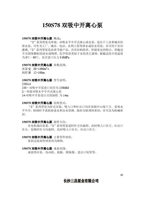
150S78双吸中开离心泵型号说明:
250S14
250-双吸中开泵进口直径为250MM
S-单级双吸水平中开式离心泵
14-双吸中开泵设计点的扬程为14m
150S78双吸中开离心泵结构型式:
“S”系列型泵为卧式安装,吸入口和吐出口均在泵轴中心线下方,泵体水平中开,检修时不需拆卸进水和出水管路。
轴封为软填料密封;亦可改为机械密封。
150S78双吸中开离心泵旋转方向:
从电机端向泵看,“S”系列型泵逆时针方向旋转,此时吸入口在左,吐出口在右,泵顺时针方向旋转,此时吸入口在右,吐出口在左。
150S78双吸中开离心泵主要零件材质:
泵的过流部件材质均为铸铁。
150S78双吸中开离心泵成套范围:
成套供应泵,电动机、底板、联轴器、进出口短管等。
63
64
65
66
67
68
69。
什么样的水泵是中开泵

什么样的水泵是中开泵
中开泵也可以称为单级双吸式离心泵,即双吸离心泵,此类型水泵只适合输送不含杂质的清水,特点是流量大、扬程低,所以又可以称为是大流量中开式离心泵,可适用于工厂、矿山、城市给排水、电站、农田排灌及各种水利工程。
中开泵运行的工作原理:
中开泵叶轮安装在泵壳里的泵轴上,由电机直接驱动,中开水泵进口阀门与进水管道相连,液本介质经底阀和吸入管道进入泵壳内,水泵出口阀门与出口管道相连,将液体介质输送到目的地,当水泵到达一定转速时,水泵压头、流量与叶轮直径有关。
中开泵的结构特点:
1、中开泵允许工作压力为2.5Mpa;即入口压力+水泵扬程≤2.5Mpa,根据泵壳所能承受的最大压力,泵体和泵盖材质采用灰口铸(1.6Mpa)。
2、可输送温度≤105℃的清水或物理化学性质类似于清水的其它液体(固体颗粒80mg/L;
3、选择油脂润滑的封闭式滚动轴承,后期维护简单,使用时间长;
4、出厂配备恒位油杯,也可用稀油润滑;
5、此型号水泵选用进口的(SKF、NSK、NTN)优质轴承,运行时间长、质量优、噪音低,水泵结构为中开式,进出口均在泵体上,后期维护维修不需要拆卸管路,只需要吊出泵盖,就可以进行检修维护,泵轴刚性好,运行更稳定,叶轮密封环为可选件,磨损后方便更换,也减少了后期水泵的维护费用。
中开泵的用途分析

中开泵的用途分析什么是中开泵?先来了解一下什么是中开泵。
中开泵,又叫中心开口离心泵,是一种离心泵。
离心泵是由一个或多个旋转叶轮转子和一个固定导向叶片的定子拼合而成的。
中心开口离心泵是在旋转轴线上设置有一个中心开口,流体通过中心孔口吸入,然后经旋转叶轮转子的离心力推着凸起转子静叶并离心组件壳体而流,最后从出口排出。
中开泵的用途离心泵具有构造简单、易于制造、维修方便、产品类型众多、使用范围广泛等特点。
而中开泵在离心泵的基础上,具备了更多优势,使得其在特定的使用领域和场景中表现得尤为突出。
下面将分析中开泵的用途及其优点。
1. 循环系统在循环系统中,中开泵可以对供水或冷却水进行输送,供应给循环系统中的设备或者机器。
中开泵的设计特点是水流中心开口,因此特别适用于输送清洗或冷却水的循环系统,防止水流中可能存在的冷凝反应,提高了管道的安全性和可靠性,不会对设备或机器造成不当影响。
2. 压缩机装置在计量装置、压缩机等的引入过程中,中开泵可以对气体进行输送。
比如说,对于空调系统或者冷藏仓库,中开泵需要将压缩机中的裂变制冷媒体带入舵门,帮助机器的运行。
3. 污水处理在污水处理过程中,中开泵是必不可少的工具。
在污水处理厂中,中开泵可以对污水进行吸排,对处理后的污水进行泄放。
由于中开泵具有自吸特性,因此可以实现对低质量污水的有效处理。
4. 工业生产在工业生产过程中,中开泵可以对温度产生不安定的气体进行输送。
例如对于发电厂的冷凝水和蒸汽管道、石油精制工艺、生产水空调系统等,均可使用中开泵,使得其能够持续产生空气,从而实现压力的平稳运生。
中开泵的这些特点和功能,使得它在很多特定的领域和场景中表现尤为突出,深受广大工业企业和消费者的好评。
Ots型单级双吸中开离心泵
Ots型单级双吸中开离心泵进入水气分离箱,使被带出的循环水分离后再重复使用。
叶轮不停地旋转,真空泵就不断地吸气和排气,最后将水泵充满水。
关于真空泵的台数,对于小型泵站,当机组少于3台时,一般选台,当机组多于4台时,一般选2台;对于中大型泵站,最好选用2台,当机组较多时,要考虑备用台。
真空泵充水的优点是充水时间短、泵站效率高、劳动强度低、易于实现泵站自动化。
缺点是投资较大。
离心泵充水是水泵运行管理的重要组成部分,相信随着水利科研人员对离心泵充水方法的不断探索,以“方便、实用、高效”为宗旨的水泵充水方法会越来越多,充水效果也会越来越好,从而为机电排灌事业的发展做出积极的贡献。
?采购前阀门选型的步骤和依据:在流体管道系统中,阀门是控制元件,其主要作用是隔离设备和管道系统、调节流量、防止回流、调节和排泄压力。
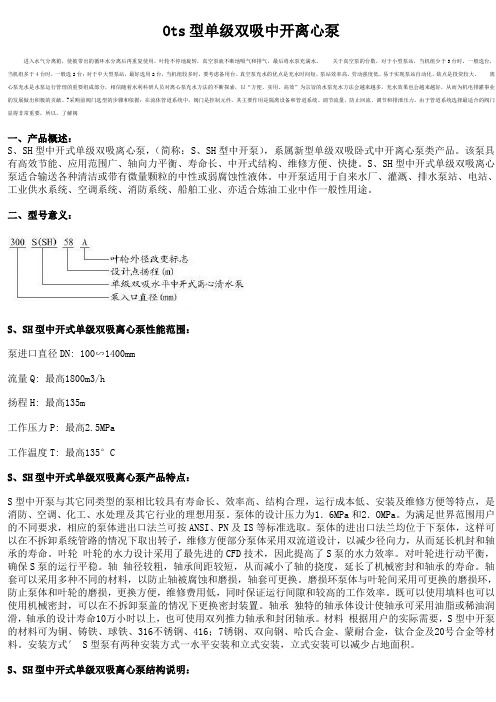
由于管道系统选择最适合的阀门显得非常重要,所以,了解阀一、产品概述:S、SH型中开式单级双吸离心泵,(简称:S、SH型中开泵),系属新型单级双吸卧式中开离心泵类产品。
该泵具有高效节能、应用范围广、轴向力平衡、寿命长、中开式结构、维修方便、快捷。
S、SH型中开式单级双吸离心泵适合输送各种清洁或带有微量颗粒的中性或弱腐蚀性液体。
中开泵适用于自来水厂、灌溉、排水泵站、电站、工业供水系统、空调系统、消防系统、船舶工业、亦适合炼油工业中作一般性用途。
二、型号意义:S、SH型中开式单级双吸离心泵性能范围:泵进口直径DN:100∽1400mm流量Q:最高1800m3/h扬程H:最高135m工作压力P:最高2.5MPa工作温度T:最高135°CS、SH型中开式单级双吸离心泵产品特点:S型中开泵与其它同类型的泵相比较具有寿命长、效率高、结构合理,运行成本低、安装及维修方便等特点,是消防、空调、化工、水处理及其它行业的理想用泵。
泵体的设计压力为1.6MPa和2.OMPa。
为满足世界范围用户的不同要求,相应的泵体进出口法兰可按ANSI、PN及IS等标准选取。
离心泵技术问答
答:介质密度的差异与泵的体积流量、压头及效率无关,但是将会对泵的重 量流量、压强和轴功率产生很大影响。这是因为在一定转速下,液体所收的离心 力虽与液体密度成正比,亦即在离心力作用下产生的压强与密度成正比,、但压 头是以 H=P/υ的形式来表示的。因此,液体密度的影响就消除了,泵的扬程-流 量曲线保持不变,但轴功率将随液体密度不同而改变。如机泵进行水联运时,因 为水的密度比实际介质密度大,所以泵的轴功率将变大,此时要注意控制流量, 不要使电机超负荷。
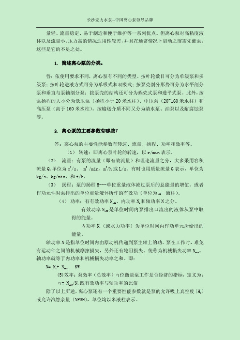
答:分析图 5-16 中的各条曲线,从流量—扬程(Q—H)曲线可看出:流量 增大时,扬程下降,但变化很小,说明流量不变则泵内的压力稳定,流量变化后, 泵的操作压力波动不大,但为了保证泵内有足够大的压力,排液量不能任意增大。
从流量—功率(Q—N)曲线可看出,流量和功率的关系是:功率的消耗随流 量的增加而增大,当流量为零时(泵出口阀全关),则功率消耗最小。故离心泵 启动时,必须关闭出口阀,否则因功率消耗大,往往造成电机跳闸或烧坏电机, 也增加了机械磨损。
从流量—效率(Q—η)曲线上可以看出效率曲线有一个效率最高点,这称 为最佳工况点。在这个最高点附近操作,才最经济合理。因此,和最高点效率相 对应的流量、扬程、功率对选择和使用泵很重要。选泵时应根据各泵的特性曲线 上表示出来的最佳工况点来选择所需要的泵。
长沙宏力水泵--中国离心泵领导品牌
图 5-16 离心泵的特性曲线图 18. 离心泵启动时应该注意什么问题? 答:离心泵启动时应该注意以下问题: 1) 离心泵在任何情况下都不允许无液体空转,以免零件损坏。 2) 离心热油泵一定要预热,以免冷热温差太大,造成事故。
3) 离心泵启动后,在出口阀门未开的情况下,不允许长时间运行,应小于 1~2 分钟。
- 1、下载文档前请自行甄别文档内容的完整性,平台不提供额外的编辑、内容补充、找答案等附加服务。
- 2、"仅部分预览"的文档,不可在线预览部分如存在完整性等问题,可反馈申请退款(可完整预览的文档不适用该条件!)。
- 3、如文档侵犯您的权益,请联系客服反馈,我们会尽快为您处理(人工客服工作时间:9:00-18:30)。
01SLOW SERIES DUAL-SUCTION PUMP()//()0.00.1This operation instructions covers the basic introduc-tion and the precautions and please read it carefully before erection and operation of the pump and the circuit connec-tion.The dual-suction pump made in Shanghai Liancheng (Group)Co.Ltd is developed on the basis of advanced know-how and has passed through a continuous quality control.What is the purpose to draw out this operation in-structions is to make it convenient for users to get familiar with the pump and have a good command of its special use.It is very important to follow the requirements on how to have the pump reliably,safely and effectively run intro-duced in this instructions so as to make sure of its relia-bility,safety and durability of running.This instructions does not cover any local provisions and operators,including the invited erection persons,sh-ould strictly follow these provisions.During he pump's run,the medium being transported,flow,flow rate,density,pressure,temperature and the mo-tor's speed must not be over the limited value set forth in the technical document so as to make sure of the pump's run in line with the provisions in this instructions and con-tract document.The pump's model/specis,running data,factory/series codes are marked on the nameplate and please refer to th-ese data in case of a question or repeated order,especially the order for spare parts.And please contact with the order for spare center of clients of Shanghai Liancheng(Group)Co.Ltd,if you need any other information or in case of a failure with the pump.There is the basic introduction for safety in this ins-tructions and it must be followed when to assemble,run and service the pump.Prior to erection and run,the per-sons for erection,specially in charge of it and for opera-tion have to read this instructions.Besides to follow the particulars for safety in the ch-apter of "Safety",the safety indications should also be dr-awn under the specific topic.Persons may be made harmful if not following the sa-fety particulars in this manual,therefor they must be ma-rked with special marks of danger.The make is:0.0SAFETY0.1MARK OF SAFETY INDICATION02()()()0.20.30.40.5The mark of electric shock warning The word:Used to not following the safety p-articulars may result in failures and malfunctions with the machine.Some other indications are directly marked on the machine,as:-The arrow expressing the run direction;-The mark expressing the run direction;These indications must be carried out and marked on the attention attracting place.All the persons responsible for the pump assembly,run,check and service must have the relative qualifications.There should be the person in charge of and supervisory among the operators.Proper training and instructions have to be given to those operators who have no capability to deal with any problems,which can be entrusted to do by this Co.if necessary.Besides,every person in charge of should know well the all contents in this instructions.Dangers may be produced to personnel safety,envi-ronment and machine and penalty and compensation for loss would be caused in case of not following the safety par-ticulars,so special attention must be paid to them.It may result in the followings if these particular are not followed:-Out of functions of the important machines or units;-Breakdown of the provided service and maintenance;-Harm to persons caused by electricity,machinery and chemical affection;-Harm to environment caused by the harmful matters.Please do follow the safety particulars set forth in this instructions,drawn out by the country and specified for o-perators in their operation.The safe and protective device must be mounted for any hot or cold components which may cause dangers by operators and the said device should not be removed in run-ning in order to avoid direct contacting with the movable parts(as the clutch).To avoid dangers to people and envi-ronment,the leakage of any harmful media to be transport-ed(as the explosive,toxic and hot media)and leakages(as0.2PERSONNEL LIMIT AND TRAINING0.3UNCONFORMITY OF THE SAFETY PARTICULARS0.4SAFETY CONSCIOUSNESS0.5SAFETY PARTICULARS TO OPERATORS/USERS03SLOW SERIES DUAL-SUCTION PUMP1.00.60.70.8()the leakages at the shaft seal)must be properly processed and the related laws,rules and the local provisions should be followed.It must be made sure that all the work of maintenance,check and erection should be done by the special persons who have been designated,certified and very familiar with this instructions and with the machine stopped,and the ru-les for stop must be followed.Both pump and its unit must be sterilized when to tr-ansport the medium harmful to health.Following the above work,finish the work below at once:all related safe and protective devices must be re-mounted and restarted and please refer to the chapter or "Running"before the machine runs again.Any parts are not allowed to be replaced until discu-ssing with this Co.and the original spare parts and acce-ssories supplied by this Co.are safe.This Co.would not be responsible for any loss caused by the use of other pats.The pump can reliably and safely run only with the specified ways of use and the limited values in the table of data must not be over under any conditions.0.6SAFETY PARTICULARS FOR MAINTENANCE,CHECK AND ERECTION0.7NO ALLOWANCE TO REPLACE ANY SPARE PARTS WITH THOSE NOT MADE IN THIS Co.0.8THE WORKING CONDITIONS OF USE WHICH ARE NOT ALLOWED1.11.2()1.1SAFETY PARTICULARS1.2TRANSPORTATIONMake a suitable preparation and process for the transporting unit.Please carry out them according the notes and safety particulars below.It is recommended the unit be horizontally placed dur-ing transportation under any conditions,because in this way,whatever mode of transport is taken,it can be stably placed without any danger(such as:highway of boat transport).To transport,the unit must be securely placed on the shipment stand and all the parts easy to be loose and re-movable should be made secure and reliable.042.0PRODUCT AND ACCESSORIES1.2.1901.2.1Lifting the pump unit with a lifterThe lifting hole of the motor is used to lift it only while not to lift the unit.To lift the pumpunit,take care of the direction of the pulling force and theangle should not be over 90,and use the lifting rope on both sides.The correct way of lifting comes as below in the drawing.2.1()SLOW2.1TECHNICAL CHARACTERSSLOW pump is single-stage dual-suction centrifugal split pump with the volute casing and the connection fl-ange is made per the preferential series of the national stan-dards.It is used for the water works,irrigation and water loggingpump station,the industrial water supply system in a power plant,air-conditioning system,dock,fire-fighting system andmany other fields.05SLOW SERIES DUAL-SUCTION PUMP 2.2MODEL MEANING2.3350mm80002.3.12.3.22.3.32.3.42.3MAIN DESIGNED PARTSAllowed value of stuffing seal leak(maximum value):The flanges of both inlet and outlet are placed on the pump casing.The radial dual-suction impeller is designed and made as required by users and features the ability to balance most of the axial force.For those pumps whose outlet diameter is below 350mm,the shaft is completely sealed to prevent it from being corroded due to the leak of liquids and the muff is stret-ched into the sealing area.The shaft seal is designed as stuffing or mechanicalseal per the need of use and guaranteed to be safe running for 8000hours.2.3.1Pump casing2.3.2Impeller2.3.3Pump shaft2.3.4Shaft sealThe normal leakage from the stuffing chamber should not be over the data in the table.The stuffing's duration would be reduced and the mechanical loss would be inc-reased if it is too less,then the stuffing gland has to be adjusted to lower the pressing extent to enlarge the leakage while adjusting the position of the gland in the reversed direction if toomore.(mm)(mm)()Means the third cutting Means as a flow-expansion typeMeans the DN of impeller (mm)Means the outlet aperture of the pump (mm)Means horizontal erectionMeans spiral casing type centrifugal pump (vertical erection)Shanghai BrandSL O (W)(I)C063.0FIELDERECTIONONTN SKF2.3.52.42.52.63.1Allowed value of the mechanical seal's leakage:Adjust the screw on the gland with hand to make the static-ring evenly forced in case of a too large mechanical seal's leakage and,if the mechanical seal or the O-ring is found damaged,replace it on time.Cooling or lubricating water pipe must be smooth wi-thout any resistance.As required in the design and running data,the pump is equipped with a bearing and a lubricating system,of which,the dry-grease lubrication is used with the imported fully closedbearing,without need for users to put in the grease during work;and the thinned oil lubrication is set with an oil cup with which the oil level can be seen and the oilcan be put in.The bearing on the free end is set with a sleeve so as to quickly replace the bearing without need to remove the rotor or the pump casing.This es NTN or SKF bearing,stable running,low noise and long duration.Horizontal or vertical erection.The accessories of the pump depend on each relative contract.Please refer to the catalogue of the pump.2.3.5Bearing and lubrication2.4ERECTION FORM2.5ACCESSORIES2.6SIZE AND WEIGHT3.1SAFETY PARTICULARSAs marked on the nameplate,to mount the elec-tric power equipment in a dangerous place shouldfollow the local provisions for anti-explosion,as well as those for the equipment to be certified after inspection and set forth by the authority in charge of approvement.The certificate of inspection must be placed near the pump unit.07SLOW SERIES DUAL-SUCTION PUMP 3.23.312312(4050mm )3456()0.04mm903.3.13.3.23.3.33.2CHECK PRIOR TO ASSEMBLY3.3ERECTION OFPUMP/UNITAll the preparations for assembly should be made readyaccording to the catalogue or the erection drawing and as required in the related standards,the concrete basis must be strong enough to make sure of a safe and reliable ass-embly and before placing the unit on it,must be solid and its surface should be smooth and flat.1.The concrete basic must be solid and its surface must be smooth and flat prior to erection.2.Insert the foot bolt into the preset hole and place the pump on the basic,then adjust the level at the shaft end or outlet one with a leveller,place pads on the place near the foot bolt and between the foot and the basic.3.After the level adjustment,grout the foot bolt and uniformly tighten it after the mortar becomes solid and adjust the level again.1.Measure and record the position of the pump.2.Put the pump unit on the basis and insert the foot bolt into the basis,then make adjustment.(Keep a 40-50mm space between the foundation and the basis if necessary to grout the foundation).3.Grout the bolt and let it be solid.4.Precisely adjust the unit and let it centred at the clutch with an adjusting screw.5.Evenly tighten the foot bolt.6.Grout the foundation if necessary at this time and then check and adjust again(with pads).It is necessary to make sure of both pump and motor to be precisely centred at the clutch,which should also be done even if both of them are supplied as an integral unit.The method:it can be regarded as being well centred for the deviation between the axial and radial rakes of the clutch not to be over 0.04mm.Evenly rotate the gauge by 90on both ends of the clutch every time and check with a vernier caliper or mi-crometer,the readings on all points must be even.Before starting the pump check the data of run-ning to make sure they are those on the nameplate,for instance:the working pressure,frequency,the tempera-ture to be transported etc.,They should conform to those on the contract and of the system.3.3.1Erection without the common foundation for bothpump and motor3.3.2Erection with the common foundation for both pumpand motor3.3.3Adjustment of both pump and motor3.4 3.4PIPELINE CONNECTIONNever take the pump as the support point of thepipeline.The upward-suck pipeline should be pl-aced in an upward inclination while the inverted-pour one ina downward inclination.The pipeline should have supportpoints near the pump and not be allowed to bear any pre-ssure or be made deformed,its weight should be no wayto become a load on the pump.For a short pipe,its nomi-nal diameter should at least be equal to that of the pumpinlet and,for a long pipe,the most economical nominal dia-meter should be upon the specific conditions.Pay attentionto the additional load on both inlet and outlet caused by thefollowings:the weight of pipe full of water,the length va-riation of a pipe because of the variation of the tempera-ture and the counter action caused due to the looseness ofthe stretcher,they should never be over the given values.The piezometer on the pump outlet must be placed closeto the outlet and not be allowed to be mounted on the backof the gate va lve at the outlet.It may cause leak from thepump if the pressure inside of the pipeline is too big or overthe allowed value and the medium being transported maybe then es-c aped into air,a fatal danger may be producedif the medium is a hot one!0809SLOW SERIES DUAL-SUCTION PUMP 4.0/RUN STOP4.1CHECK BEFORE RUNNINGThe followings must be checked before starting the Pump:*If all instruments and meters work accurately *The foundation with the pump is tightened with the basis*The clutch and the pump unit are well corrected *The pipeline is connected per the requirement *The motor is mounted per the instructions *The rotor is easy to be moved by hand(at least once cycle)*The protective cover of the cluth is put on *The operator knows well the possible failures and the safety rules which have to be followed *The overload is removed*The shaft seal is mounted per the instructions *The auxiliary devices,if supplied,are mounted per the instruction*All the bearings are well lubricated *The pump is exhausted*The oil level is OK is case of the thinned oil lubri-cation to bearings3.4.13.4.23.53.4.1Auxiliary pipelines3.4.2Protective cover of the clutchAll the necessary auxiliary pipelines are mounted be-fore the pump's ex-works.Erection of the auxiliary pipelines can be helpful for the normal work of the pump,therefore it isimportant to mount them.It is prohibited to have the pump work without the protective cover and the operator must mount it case or no need by the user due to a special requirement.Please check again If the calibration is correct then.It must be easy to move the clutch to have it drive the rotating shaft with hand.Check if all pipelines are secure and can work normally.3.5FINAL CHECK4.1******()*******4.24.34.420%***()***4.4.14.4.24.2SHAFT SEAL4.3EXHAUST4.4RUNNINGPay attention to the leakage in case of a mechanical seal and check and replate it if it goes more.Take care not to pull the stuffing along with the directionof its lengthin case of a stuffingseal and,if it can not be put in theshaft unless enlarging the internal diameter,please use an axial spiralstretch,about 20%of the stuffing must be pre-ssed when to put it in each time.Please separately place them in case of the stuffing is hybrid with different varieties,how-ever,same ones have to be put on both sides of the stuff-ing ring and the two glands.Both pump and pipeline must be completely exhausted before starting the pump and pour them with the medium.The cork hole on the upper of the pump casing can be used for exhaust.The pump can safely run only with a correct ro-tating direction of the impeller,otherwise,if witha wrong one,it can not reach the points of working con-ditions and may produce vibration and overheat,the pump unit or the shaft seal may also be damaged.The said di-rection must be identical to that of the arrow marked on the pump casing and can be verifie at once the pump is started.Stop running immediately if it is wrong and the pump is not allowed to be frequently started.Make sure no foreign matters are inside of the pump casing before check and prohibit any hand or other objects from being into the pump!Prohibit the pump from dry moving!the outlet valve;*Fully open outlet valve;*Open all auxiliary pipeline(cooling,heating,sealing,washing and lubricating liquid),and check the flow;*Start the motor after the above steps;*It can be seen on the piezometer for the pressure to rise when the system starts to tansport a medium,then slowly open the outlet valve;*Take the start procedures per the related instruc-tions if the motor is directly;The outlet valve is closed only at the pump's s-tarting and stopping and the running points of thepump is controlled through the opening adjustment of the valve.4.4.1Check the rotating direction of the rotorSLOW SERIES DUAL-SUCTION PUMP 4.4.3Q HQAQHQminQ Q QminB NPSH NPSHr(NPSH)a (NPSH)r(NPSH)aQ H()NPSHNPSH4.4.3Working range of the pumpBased on the Q-H characteristic curve,the flow Q can be self adjusted to meet with the head's variation while the allowed range for the pump to work is limited,caused with various reasons.A.Working limit of the load on the low flow partThis limit is shown with Qmin in the said curve or with the extended line of the curve which is not drawn out.As shown in the drawing:The pump is not allowed to work in the range of Q=O-Qmin,otherwise long running within this range may cause the mechani-cal load to greatly increase,thus making the parts no way to bear,but an instantaneous pass through this range is allowed,such as starting the pump.B.Limits of NPSH of partial load and within the overloadrangeThese two limits can be decided upon the relationship between the necessary (NPSH)r and the apparatus'(NPSH)a and gained with the following way:have the intersection points of both (NPSH)r and (NPSH)a projected on the Q-H characteristic curve,the two projected points decide the work limit (the part under the curve).It is not required to check the work limits of NPSH when the pump works under the designed working conditions,which has to be done while the system varies.Inquire to the nearest post-sale service centre if necessary.4.4.44.5.14.5.2()()1()25.15.4()5.15.2/4.54.64.4Stop4.5STOP/STORAGE/SERVICE4.6RUNNING AFTER STORAGEClose the outlet valve.Do not close the inlet valve when to stop the pump and make sure that the unit can be slowly stopped when to turn off the motor.The pump sh-ould have a proper period of back movement and,during which,the heat source must be cut off,thus letting the me-dium being transported completely cooled so as to avoid any heat produced inside of the pump.The inlet valve must be closed in case of a long time stop of the pump as well as the auxiliary pipelines.The shaft seal of the pump should be lubricated with sealing liquid even if in the stop status.Remove the medium left inside of both pump and pipelines in the freezing season or in the long time stop.Each pump made in this Co.is strictly inspected atex-works,to store it,the following measures are suggestedto take:Remove the pump from the pipeline and keep itwellThis Co.has made full preparations for the pump it supplies.You may keep it in a dry place and one year can be kept in case of indoor storage.1.Keep the pump in the assembled status and perio-dically check its working condition.In the long time stop,to ensure that it can be startedat any time and prevent any precipitates from forming in-side of the pump and at the inlet,start it once every 1or 3months(for about 5minutes)and,before that,check itsrunning condition to make sure that there is enough liquid inside of it for starting it.2.Check per 5.1-5.4before to keep it.Spray a protective agent onto the inner wall of the pump casing,especially the space of the impeller,and the suction inlet and drain outlet,then cover both inlet andoutlet with plastic or the like.Check and service per 5.1and 5.2before running.Besides,please refer to the chapter of "Run,start/stop".All the safe and protective devices should there after be remounted and put into use before starting the pump unit.4.5.1Storage of a new pump4.5.2Measures taken in a long time stopSLOW SERIES DUAL-SUCTION PUMP5.05.1*****3090100*****1.02.0bar*5.25.2.15.2.25.1GENERAL PROVISIONS5.2SERVICE/CHECKIt is required that all the work for service,check and erection must be carried out by the special persons desig-nated,qualified and very much familiar with this instructions.A periodical service plan can avoid and expensive cost of service,have the pump without any failures and reliably running with a rather low cost of service.It should be done to cut off the power for the above work to prevent the pump unit from abrupt starting.The pump must be sterilized before transporting any liquids harmful to health and both people and environment would not be harmed only with the medium completely drained out,and at the same time,related provisions should also be followed.Pay special attention to the followings during running of the pump:*Take care of the three-phase current value all the time*The pump must run stably*The pump is not allowed to run without any liquid *To prevent the temperature rise of the medium,the pump can not run for a long time with the outlet valve closed*The bearing's temperature is not allowed to be over 90when the ambient one is 30;and not over 100while the ambient one goes rising*Periodically check the oil level in case of a thinned oil lubrication for the bearing*The inlet valve must not be closed at pump's running *Periodically check and start the spare pump*Check the elastic elements on the clutch and replace them at once worn-out is found*In case of not the medium being transported to be used as the sealing,cooling and lubricating liquids,then the liquid used must be guaranteed with its pre-ssure higher than the inlet one by 1.0-2.0bar*If any leak at the stuffing happens with the pump using the stuffing seal,slightly press the stuffing gland till less water drops.Take the maintenance per the chapter of "Shaft seal"in this instructions.5.2.1Running control5.2.2Maintenance of shaft seal5.2.35.3.15.3.2()1()()2345()675.35.2.3Maintenance of bearing5.3.1Basic provisions and suggestions5.3.2Prepartions for removalNo need of maintenance for the bearing with greaselubricated deep-ditch ball.Use the related instruction for the maintenance of thebearing with the thinned oil lubricated.Before removal,it should be made sure that the pumpcan not abruptly start and must be cooled to the ambient temperature and completely drained,both inlet and outlet valves must be closed and the pressure must be released.Removal and reassembly should be done according to some related information.Both maintenance and service must be done by thespecial persons and the original spare parts should be used.The safety particulars must be followed and the ope-ration concerning the motor has to be done according to the related instructions and provisions.Both removal and reassembly must be upon the re-lated drawings.In case of a failure,please contact with the servicedept of this Co..It is unnecessary to remove both inlet and outletpipelines and calibrate the pump's position again if only to remove the rotor of the pump.Remove the rotor part per the following steps:1.Close both inlet and outlet valves and open the drain cork(on the bottom)and the exhaust cork(on the top)to completely drain the water pump;2.Remove all auxiliary pipelines on the pump;3.Remove the protective cover of the clutch;4.Screw out all screws on the middle surface;5.Loosen the screws on the flanges and separate the pump casing from its cover with the cover-out s-crews,then lift the pump cover with a lifter andplace it in a safe place and further overhaul or re-move the inside of the pump;(Attention:take care not to scratch the seal plane between the middle surface of the cover and the casing);6.Drain out the oil if the thinned oil lubrication is used for the bearing;7.Remove the connection bolt between both bearing body and bracket and loosen the nut and connection bolt on the bearing cover on the non-driving end;5.3REMOVALSLOW SERIES DUAL-SUCTION PUMP8(350mm)91011(350mm)12131415()16()1718192021()O5.48.Have the bearing body out of the notch,(that means the one with a notch of the pump of an outlet dia-meter less than or equal to 350mm;the one without the notch has to be lifted together with the rotor),and lift the rotor out of the pump casing and place it in a safe place for further removal;9.Remove the bearing body or gland;10.Loosen and remove the locking nut and thrust wa-sher;11.Remove the bearing with a deep-ditch ball fromthe shaft,including the bearing sleeve;(for the pump of an outlet diameter larger than 350mm,remove the bearing together with its body);12.Remove the bearing gland;13.Remove the water-baffle ring;14.Remove the seal gland;15.Remove the seal body(means that has the structurewith such a seal body);16.Remove the muff(first remove the nut on the muffif any);17.The impeller,because of an interval fit with theshaft,is easy to be removed and you may slightly knock on the hub of it with a wood hammer or copper rod if no way to remove;18.Remove the other muff,including the seal bodyand gland;19.Remove the clutch of the pump;20.Remove the bearing body;21.Loosen the elastic baffle ring of the bearing aswell as the locking nut to let the bearing with a deep-ditch ball out.Take a contrary sequence to that for removal to rea-ssemble and use the overall erection drawing and the tables for each part as reference.Assembly and removal of the shaft seal,bearing and seal ring should follow the standard assembly technology or erection instructions.Fill the oil from the oil hole on the upper of the be-aring body to the required level in case of the bearing using the thinned oil lubrication.The force to tighten must be proper and not too tight and all the locking nuts must be evenly and symmetrically tightened.The skeleton oil-seal of both O-ring and baffle ring must be replaced and the place where it is mounted must be cleaned.Besides,all the sealing elements must be put on the proper positions before erection.5.4REASSEMBLY()The pump shaft must be stably placed when to mount the rotor.Clean all the fitting places,including the fitting between threads and intervals,and coat them with the ass-embling adhesive,place the required pins on the pump shaft when to assemble.Pay attention to the rotating direction of the impeller with an interval fit and follow the drawing below to corr-ectly mount it.Mount the seal rings on both ends of the pump on thedriving surface of the rotor and make sure of the beveling of the rings to be outside(facing towards the bearing).To assemble the seal ring with a position-pin,it should be put it.The following elements are mounted on the driving end of the motor.Put the muff on the shaft and make sure that the im-peller's pin is inlaid into the pin channel.。