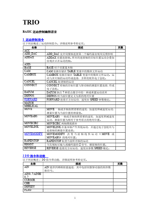
第八课 Movement shaft encoder(轴角编码器)
TRIO BASIC中文手册
描述 ERROR_LINE 包括最后 BASIC 程序出错的行数
PMOVE 包括任务缓存的状态 PROC 获得特定过程参数 PROC_LINE 返回特定程序的当前行 PROCNUMBER 包括当前被选择运行的任务数 PROC_STATUS 返回特定过程的状态
RUN_ERROR 包括在特定任务产生的 BASIC 错误数 TICKS 包括当前任务时钟脉冲
描述
页数
8 轴参数
以下列表概述了轴的参数,详细描述参考特定页。
命名
ACCEL ADDAX_AXIS ATYPE AXISSTATUS CLOSE_WIN CLUTCH_RATE CREEP DATUM_IN DECEL DEMAND_EDGES DPOS DRIVE_STATUS D_GAIN ENCODER ENDMOVE ERRORMASK FAST_JOG FASTDEC FE FE_LIMIT FERANGE FEMIN FHOLD_IN FHSPEED FS_LIMIT FWD_IN FWD_JOG
描述 任何两个有效表达式的加 任何两个有效表达式的减 任何两个有效表达式的乘积 任何两个有效表达式的除 如果表达式 1 等于表达式 2 返回真,否则返回假 如果表达式 1 不等于表达式 2 返回真,否则返回假 如果表达式 1 大于表达式 2 返回真,否则返回假 如果表达式 1 大于等于表达式 2 返回真,否则返回假 如果表达式 1 小于表达式 2 返回真,否则返回假 如果表达式 1 小于等于表达式 2 返回真,否则返回假 返回表达式的绝对值 返回表达式的反余弦 两有效 BASIC 表达式在整数部分的相应位执行与操作 返回表达式的反正弦 返回表达式的正切值 返回非零表达式的反正切值 清除特定 VR 变量的特定位
正交编码器

正交编码器 接口 (QEI)
第 16 章 正交编码器接口 (QEI)
目录
本章包括下列主题: 16.1 16.2 16.3 16.4 16.5 16.6 16.7 16.8 16.9 16.10 16.11 16.12 16.13 模块简介 ...................................................................................................................... 16-2 控制和状态寄存器 ....................................................................................................... 16-4 可编程数字噪声滤波器 ................................................................................................ 16-9 正交解码器 ................................................................................................................ 16-10 16 位向上 / 向下位置计数器 ...................................................................................... 16-12 QEI 用作备用 16 位定时器 / 计数器 ........................................................................... 16-16 正交编码器接口中断 .................................................................................................. 16-17 I/O 引脚控制 .............................................................................................................. 16-18 低功耗模式下的 QEI 工作 .......................................................................................... 16-19 复位的影响 ................................................................................................................ 16-19 设计技巧 .................................................................................................................... 16-21 相关应用笔记 ............................................................................................................ 16-22 版本历史 .................................................................................................................... 16-23
编码器安装注意事项(1)ppt课件

技术课:徐少华
2010-1-14
FANUC伺服分离型编码器
一体式伺服分离型编码器
编码器名称
αA 1000S
订单号
A860-0372-T001
最高转速*
4000r/min
TTL/串行信号
*其他技术参数请参考伺服放大器规格说明书
-2-
FANUC伺服分离型编码器
分体式伺服分离型编码器αiCZ Sensor
*其他技术参数请参考伺服放大器规格说明书
-6-
一体式分离型伺服编码器典型安装结构
丝杆末端连轴器直连
ai 主轴电机
非1:1齿轮减速 箱或同步带轮
ai SPM
同步带传动
ai 主轴电机
丝杆
αA1000S
SDU
连轴结直连
αA1000S
丝杆
非1:1齿轮减速 箱或同步带轮
ai SPM
连轴结直连
SDU
-7-
一体式分离型主轴编码器典型安装结构
FANUC主轴分离型编码器
分体式主轴分离型编码器αiBZ
内装主轴电机
的反馈元件,普通主轴电机上也可使用,1vpp信号
编码器名称
防水型
订单号
非防水型
αiBZ Sensor 96
A860-2150-T111
αiBZ Sensor 128H
A860-2150-T211
αiBZ Sensor 192H
A860-2150-T311
-3-
FANUC主轴分离型编码器
一体式主轴分离型编码器
编码器名称
αi position coder α position coder S
订单号
A860-2109-T302 A860-0309-T352
快速入门篇十四:运动控制器基础轴参数与基础运动控制指令
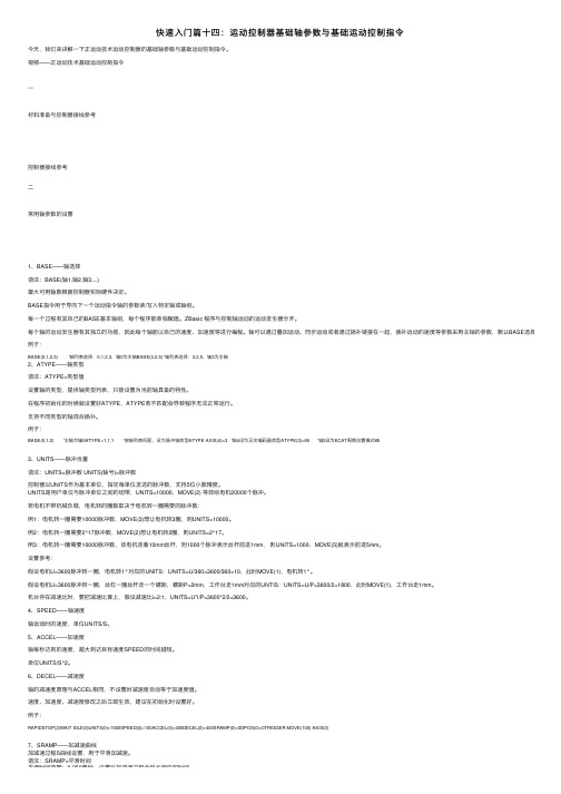
快速⼊门篇⼗四:运动控制器基础轴参数与基础运动控制指令今天,我们来讲解⼀下正运动技术运动控制器的基础轴参数与基础运动控制指令。
视频——正运动技术基础运动控制指令⼀材料准备与控制器接线参考控制器接线参考⼆常⽤轴参数的设置1、BASE——轴选择语法:BASE(轴1,轴2,轴3,...)最⼤可⽤轴数根据控制器实际硬件决定。
BASE指令⽤于导向下⼀个运动指令轴的参数读/写⼊特定轴或轴组。
每⼀个过程有其⾃⼰的BASE基本轴组,每个程序能单独赋值。
ZBasic 程序与控制轴运动的运动发⽣器分开。
每个轴的运动发⽣器有其独⽴的功能,因此每个轴能以⾃⼰的速度、加速度等进⾏编程。
轴可以通过叠加运动、同步运动或者通过插补链接在⼀起,插补运动的速度等参数采⽤主轴的参数,默认BASE选择的第⼀个轴例⼦:BASE(0,1,2,3) '轴列表选择:0,1,2,3,轴0为主轴BASE(3,2,5) '轴列表选择:3,2,5,轴3为主轴2、ATYPE——轴类型语法:ATYPE=类型值设置轴的类型,提供轴类型列表,只能设置为当前轴具备的特性。
在程序初始化的时候就设置好ATYPE,ATYPE若不匹配会导致程序⽆法正常运⾏。
⽀持不同类型的轴混合插补。
例⼦:BASE(0,1,2) '主轴为轴0ATYPE=1,1,1 '按轴列表匹配,设为脉冲轴类型ATYPE AXIS(4)=3 '轴4设为正交编码器类型ATYPE(3)=65 '轴3设为ECAT周期位置模式653、UNITS——脉冲当量语法:UNITS=脉冲数 UNITS(轴号)=脉冲数控制器以UNITS作为基本单位,指定每单位发送的脉冲数,⽀持5位⼩数精度。
UNITS是⽤户单位与脉冲单位之间的纽带,UNITS=10000,MOVE(2) 等效给电机20000个脉冲。
若电机不带机械负载,电机转的圈数取决于电机转⼀圈需要的脉冲数:例1:电机转⼀圈需要10000脉冲数,MOVE(3)想让电机转3圈,则UNITS=10000。
FANUC伺服调整教材

①设定1902#0#1=0
#7 1902 #6 #5 #4 #3 #2 #1 ASE #0 FMD
#1:ASE
#0:FMD
FSSB的设定方式为自动设定方式时 0:自动设定未完成。 1:自动设定已经完成。 0:FSSB的设定方式为自动方式。 1:FSSB的设定方式为手动方式。
14
BEIJING-FANUC
2020
2001 1820 2084/2085 2022 2023 2024 1821
18
BEIJING-FANUC
第一章 伺服电机规格及初始化
1、初始化设定位
设定初始化设定位
#7 初始化 设定位 #1:DGP 0:进行伺服参数的初始设定。 1:结束伺服参数的初始设定。 #6 #5 #4 #3 #2 #1 DGP #0
3
BEIJING-FANUC
目录
四、自动增益调整
五、加工条件选择功能 第四章:SERVO GUIDE软件的使用及调试方法 一、Servo Guide软件介绍 二、Servo Guide连接 三、 Servo Guide调整步骤 第五章:伺服调整实例分析 一、工件表面光洁度调整案例
16
BEIJING-FANUC
第一章 伺服电机规格及初始化
四、伺服初始化
伺服初始化是在完成了FSSB连接与设定的基础上进行电机的一转移动量以 及电机种类的设定。伺服电机必须经过初始化相关参数正确设定后才能够 正常运行。
设定参数3111后,伺服设定画面能够显示。
第一章 伺服电机规格及初始化
②按伺服电机连接顺序设定参数1023的值。 1023 伺服轴号
设定控制轴为放大器连接的第几个伺服轴,通常控制轴号与伺服轴号设定 相同。
SICK绝对式编码器
R=最 小 弯 曲 半 径4 0 mm
其 它 公 差 遵 循DIN ISO-2768-mk标准
出线方式 径向出线式
径向插头式
附件 接线电缆 通孔轴套 S S I串 口 转 并 口 模 块
C1-6
技术参数
机械参数
外径 轴径 启 动 转 矩( 2 0℃) 工 作 转 矩( 2 0℃) 瞬时惯量 最大允许转速 最大角加速度 元件轴允许跳动
轴向出线式
径向插头式
轴向出线式
技术参数
机械参数
外径 轴径 启 动 转 矩( 2 0℃) 工 作 转 矩( 2 0℃) 瞬时惯量 最大允许转速 最大角加速度 元件允许轴跳动
轴承使用寿命 工作温度 存储温度 允 许 相 对 湿 度1) 抗振性能
外壳防护等级 IEC 60529
质 量5)
A R S 6 0盲 孔 型
电气参数
工作电压 工作电流
测量量程 分辨率 角度分辨率 测量误差
重复精度 角度分辨率偏差
测量值回差 响应阈值 输出接口 输出码
编 码 方 向6) “控制输入”的 "电 脉 冲"信 号 零 位 设 定 时 间7) 上电初始化时间 EMC8)
10-32V DC SSI:60mA 并 口:90mA
1圈
2...32,768(参见 订货 信息) 360°/分辨 率 2 n 分 辨率: 0.035° 非2 n 分 辨 率: 0.046° 0.005° 2 n 分 辨 率: 0.005° 非2 n 分 辨 率: 0.016°
分辨率 1...32,768
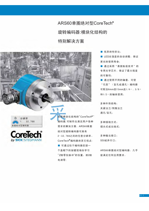
单圈绝ch 旋转编码器:模块化结构的 特别解决方案
■ 优异的性价比; ■ LED光 强 度 的 自 动 调 整 , 保 证 更长的使用寿命; ■ 通过采用“表面贴装技术”的 专用光学芯片,保证了最大程度 的可靠性; ■ 通过使用不同的轴套,可使 “孔型”(盲孔或通孔)编码器 可 配 合6mm至1 5mm及1/ 4〃 、3 / 8〃 和1/2〃 的 轴 来 使 用 ;
SEW编码器手册
18/005/98SEW Encoder SystemsManualEdition 07/990919 6412 / 07992SEW encoder systems01861AEN Fig. 1: Unit designation of SEW encoder systems E S 1 T E Incremental encoder (encoder)A Absolute encoder N Proximity sensor X Non-SEW encoder S Spread shaft V Solid shaft H Hollow shaft E n c o d e r t y p e S h a f t d e s i g n S p e c i f i c a t i o n I n t e r f a c e t o e v a l u a t i o n A Design as mounting device C V = 24 V , HTL with zero track and negated signals R V = 24 V , TTL RS-422S V = 24 V , sin/cos 1 V T V = 5 V , TTL RS-422Y SSI interface 6 Number of pulses per revolution (proximity sensor)DC DC DC SS DC 12DesignPage 1System Description (4)1.1System overview (4)2Technical Data (7)2.1Technical description (7)2.1.1Incremental encoders with TTL and HTL signals (7)2.1.2Incremental encoders with high-resolution sin/cos signals (9)2.1.3Absolute encoders with MSSI interface (10)2.1.4Resolver (12)2.1.5Proximity sensors (13)2.2Incremental encoders (14)2.2.1Incremental encoders with spread shaft (14)2.2.2Incremental encoders with solid shaft (15)2.3Absolute encoder (16)2.4Resolver (17)2.5Proximity sensors (18)2.6Mounting devices (19)3Installation (20)3.1General information (20)3.2Incremental encoders (21)3.2.1Encoders for MOVITRAC® 31C frequency inverters (21)3.2.2Encoders for MOVIDRIVE® MDV60A drive inverters (22)3.3AV1Y absolute encoder (24)3.3.1Absolute encoder with MOVIDYN® MAS/MKS51A servo controller (24)3.3.2Connection of absolute encoder to MOVIDRIVE® MDS60A drive inverter (25)3.3.3Absolute encoder with MOVIDRIVE® MDV60A drive inverter (25)3.4Resolver (26)3.4.1Resolver with MOVIDYN® MAS/MKS51A servo controller (26)3.4.2Resolver with MOVIDRIVE® MDS60A drive inverter (27)3.5Proximity sensors (28)3.6Extended motor versions with encoder and mounting devices (29)3.6.1Incremental encoders ES1_/ES2_/EV1_ (29)3.6.2Encoder mounting devices ES1A/ES2A/EV1A (31)3.6.3Absolute encoder AV1Y (34)3.6.4Encoder mounting devices AV1A (36)3.7Pre-fabricated cables (37)SEW encoder systems34SEW encoder systems 11System Description 1.1System overview 01863BEN Fig. 2: System overview, SEW drive electronics and encoder systems Electronically controlled drive systems require actual value sensing and speed feedback; drives with synchronous motors also require the angle of the rotor position. As a systems supplier, SEW offers a comprehensive range of encoder systems.Various mounting devices are available to connect non-SEW encoders to SEW motors.Proximity sensors represent an inexpensive and easy-to-fit solution, if all that is required is theinformation about whether or not the drive is turning and in which direction.Encoders Absolute encoders and resolvers Encoder systems for asynchronous AC motors Encoder systems for synchronous motors1SEW encoder systems for asynchronous AC motors:•Incremental encoders-for5V DC supply voltage and with 5 V TTL signal level according to RS-422recommended for operation with the MOVITRAC® 31C frequency inverter-for24V DC supply voltage and with high-resolution sinusoidal signal levelrecommended for operation with the MOVIDRIVE® drive inverter-for24V DC supply voltage and with 5 V TTL signal level according to RS-422-for24V DC supply voltage and with 24V HTL signal level•Absolute encoder-for15V DC supply voltage and with MSSI interface-for24V DC supply voltage and with MSSI interface and two sinusoidal tracks•Proximity sensors-with six pulses per revolution-with A track or A+B track•Mounting devices for non-SEW encoders-mounting of spread shaft-mounting of full shaft with couplingSEW encoder systems for asynchronous servomotors:•Incremental encoders-for24V DC supply voltage and with high-resolution sinusoidal signal levelstandard feature in CT/CV motors-for24V DC supply voltage and with 5 V TTL signal level according to RS-422•Absolute encoder-for24V DC supply voltage and with MSSI interface and two sinusoidal tracksSEW encoder systems for synchronous servomotors:•Resolverstandard with synchronous servomotors for speed control•Absolute encoder15/24 V DC supply voltage with MSSI interfaceEncoder selection based on setting range:•Setting range up to 1:3000-with asynchronous AC motors → encoder with TTL signals and1024 increments/revolution-with synchronous motors → built-in resolver•Setting range up to 1:5000-with asynchronous AC motors → encoder with high-resolution sinusoidal signal levels-with asynchronous servomotors → encoder with high-resolution sinusoidal signal levelsSEW encoder systems56SEW encoder systems 1All encoder systems at a glance: *recommended encoder for operation with MOVITRAC ® 31C **recommended encoder for operation with MOVIDRIVE ® Mounting devices for non-SEW encoders Name For SEW motor size Type of encoder Shaft Specification Supply Signal ES1T*CT/DT 71...100Encoder Spread shaft - 5 V DC controlled 5 V DC TTL RS-422ES1S**24 V DC 1 V SS sin/cos ES1C 24 V DC HTL ES1R 5 V DC TTL RS-422ES2T*CV/DV 112...132S 5 V DC controlled 5 V DC TTL RS-422ES2S**24 V DC 1 V SS sin/cos ES2C 24 V DC HTL ES2R 5 V DC TTL RS-422EV1T*CT/CV71...180DT/DV71...225Solid shaft 5 V DC controlled 5 V DC TTL RS-422EV1S**24 V DC 1 V SS sin/cos EV1C 24 V DC HTL EV1R 5 V DC TTL RS-422NV16DT/DV 71...132S Proximity sensor Solid shaft A track 24 V DC 6 pulses/revolu-tion, NO contact NV26A+B track AV1Y DS56DY71...112CT/CV71...180DT/DV71...225Absolute encoder Solid shaft -15/24 V DC MSSI interface and 1 V SS sin/cos Name For SEW motor size Type of encoder Shaft Specification Supply Signal ES1A DT71...100Non-SEW encoder Spread shaft -Configured as mounting device ES2A DV112...132S EV1A DT/DV71...225Solid shaft AV1A DS56, DY71...112Solid shaft XV1A DT/DV71...225Solid shaftSEW encoder systems722Technical Data2.1Technical descriptionThis chapter explains the various types of signals, signal tracks and signal levels. The signal tracks are represented in the form of timing diagrams.Encoders have a sturdy light metal housing and generously sized precision ball bearings. Their solid metal housing protects the encoders against interference, which lends them a high degree of electromagnetic compatibility.2.1.1Incremental encoders with TTL and HTL signalsEncoders convert the angle of rotation input parameter into a number of electrical pulses. This is performed by means of an incremental disc incorporating radial slits permitting the passage of light. These slits are scanned by opto-electronic means. The number of slits defines the resolution (pulses/revolution).Signal tracks:SEW encoders are encoders with two tracks and one zero pulse track, which results in six tracks due to negation. Two light barriers are arranged at right angles to one another in the encoder. They supply two pulse sequences on tracks A (K1) and B (K2). Track A (K1) is 90° ahead of B (K2) when the encoder is turning clockwise (to the right as viewed looking onto the motor shaft, the “A” side).This phase relationship is used for determining the direction of rotation of the motor. The zero pulse (one pulse per revolution) is sensed by a third light barrier and made available on track C (K0) as a reference signal. With TTL encoders, tracks A (K1), B (K2) and C (K0) are negated in the encoder and made available on tracks A (K1), B (K2) and C (K0) as negated signals.01877AXXFig. 3: TTL signals with zero track and negated signalsHTL signals with zero track, but without negated signals 90°90°180°360°A (K1)A K1()B (K2)B K2()C (K0)C K0()8SEW encoder systems 2Signal levels:•TTL (T ransistor T ransistor L ogic) version The signal levels are V low ≤ 0.5 V and V high ≥ 2.5 V. The TTL signals are transmitted symmetri-cally and evaluated differentially. This design makes them resistant to asymmetrical interference and ensures good EMC behavior. The signal is transmitted in accordance with the RS-422 inter-face standard.Units with a 5 V DC encoder supply voltage, e.g. MOVITRAC ® 31C, allow the user to measure the actual supply voltage at the encoder via sensor leads. The supply voltage is corrected to 5 V DC and compensates for the voltage drop along the supply cable to the encoder. Encoders with 24 V DC supply voltage do not require any supply voltage compensation and, thus, no sensor leads.The maximum permissible distance between encoder and inverter is limited by the maximum pulse frequency of the encoder signals. SEW permits a maximum distance between encoder and inverter of 330 ft. (100 m).02542AEN Fig. 4: View of TTL signal levels •HTL (H igh-voltage T ransistor L ogic) version The signal levels are V low ≤ 3 V and V high ≥ V B minus 3.5 V. The HTL encoder is evaluated without the negated tracks; the signals cannot be evaluated differentially. The HTL signals are, therefore, suscep-tible to asymmetric interferences affecting the EMC behavior.V B is the encoder supply voltage in the range of 10 to 30 V DC , with 24 V DC +/- 20% being the most common value. HTL encoders do not require any supply voltage compensation and, thus, no sensor leads. The large voltage range between V high -V Low results in a high current consumption. A fact that has to be taken into consideration when planning the encoder supply.The maximum permissible distance between encoder and inverter is limited by the maximum pulse frequency of the encoder signals. SEW permits a maximum distance between encoder and inverter of 330 ft. (100 m).02543AEN Fig. 5: View of HTL signal levels 552.52.50.50.500TTL K K V [V ]DC "1" range "1" range "0" range "0" range V [V ]DC 2420.503HTL K V [V ]DC "1" range "0" rangeSEW encoder systems922.1.2Incremental encoders with high-resolution sin/cos signalsEncoders with high-resolution sin/cos signals are referred to as sine encoders. They provide two sine signals offset by 90°. The zero passages and the amplitudes (arc tan) of the sine/cosine waves are evaluated. This means the speed can be determined with a very high resolution. This encoder is suitable for drives which are operated with a wide setting range in conjunction with the require-ment to move smoothly at low speed.Signal tracks:SEW sinusoidal encoders are also dual-track encoders with a zero pulse and negated signals,resulting in six tracks. The 90° offset sine signals are on track A (K1) and B (K2). One sine half-wave per revolution is provided at track C (K0) as the zero pulse. Tracks A (K1), B (K2) and C (K0)are negated in the encoder and made available on tracks A (K1), B (K2) and C (K0) as negated sig-nals.01917AXXFig. 6: sin/cos signal s with zero track and negated tracksSignal levels:•The sine/cosine signals are superimposed on a DC voltage of 2.5 V. They have a peak-to-peak voltage of V SS = 1 V. This arrangement avoids voltage zero during signal transmission. The sine/cosine signals are transmitted symmetrically and evaluated differentially. This design makes them resistant to asymmetrical interference and ensures good EMC behavior. The signal is transmitted in accordance with the RS-422 interface standard. The supply voltage is 24 V DC .Sine encoders do not require any supply voltage compensation and, thus, no sensor leads.The maximum permissible distance between encoder and inverter is limited by the maximum pulse frequency of the encoder signals. SEW permits a maximum distance between encoder and inverter of 330 ft. (100 m).90°90°180°360°A (K1)A K1()B (K2)B K2()C (K0C C0()1V10SEW encoder systems 22.1.3Absolute encoders with MSSI interface SEW absolute encoders have a code disc with Gray Code instead of the incremental disc. This code disc is scanned by opto-electronic means. Every angle position has a unique code pattern assigned to it. The absolute position of the motor shaft is determined using this code pattern. The special feature of Gray Code is that only one bit changes with the transition from one resolvable angle stepto the next. This means the possible reading error is max. 1 bit.01927AXX Fig. 7: Code disc with Gray Code Multi-turn:In addition to the code disc for sensing the angle position, multi-turn absolute encoders have addi-tional code discs for absolute sensing of the number of revolutions. These code discs are only sep-arated from each other by one gear unit stage with the reduction i = 16. With three additonal code discs (number usually installed), 16 x 16 x 16 = 4096 revolutions can be resolved absolutely.02383AEN Fig. 8: Arrangement of code discs A single-turn absolute encoder with 12 bit resolution requires 12 pulses to display the 4096 mea-suring steps per revolution. A multi-turn absolute encoder with three additional code discs requires 12 additional pulses to display the 4096 distinguishable revolutions.Single-turn evaluation Pulse 123456789101112Data 20 21 22 23 24 25 26 27 28 29 210 211 Measuring steps per revolution in addition with multi-turn evaluation Pulse 131415161718192021222324Data 20 21 22 23 24 25 26 27 28 29 210 211 distinguishable revolutions i = 16i = 16i = 16Code discs for sensing the number of revolutions Code disc for sensing of angle position Decimal Gray Code Decimal Gray Code 00000811001000191101200111011113001011111040110121010501111310116010114100170100151000Signal outputs:Every scanned code pattern is a parallel data package and is read by a parallel/serial converter. The inverter must request the position value with a defined pulse sequence in order to transmit a posi-tion value from the encoder to the inverter. The pulse sequence starts by converting the current parallel data package and transmitting it to the inverter. The input of the parallel/serial converter is inhibited by the monoflop for the duration of the pulse sequence.01923AENFig. 9: Signal conditioning in absolute encoders with SSI interfaceIn addition to the absolute angle position, the SEW absolute encoders generate the incremental encoder signals A (K1), A (K1), B (K2)und B (K2) and make them available as 1 V SS sine signals.Signal transmission:SEW absolute encoders have an SSI interface (SSI = S ynchronous S erial I nterface) to transmit the absolute value signals and a RS-485 interface for transmission of the 1 V SS sine signals.01928AENFig. 10: Pulse diagram of data transmission via SSI interfaceInverterCycleSerialdataParallel dataCode discDriver InputcircuitSchmitt trigger P a r a l le l /S e r ialconverterPhoto transmitter Photo receiver MonoflopShift SI SOCycleSerialdataMonoflop P/SParalleldata2.1.4ResolverThe resolver determines the absolute position of the motor shaft. It consists of a rotor coil and two stator windings offset by 90° in relation to each other. It operates according to the principle of the rotary transformer. Furthermore, the resolver has one auxiliary winding each in the stator and on the rotor in order to transfer the supply voltage to the rotor without brushes. Both rotor windings are electrically connected.01931AEN Fig. 11: Schematic diagram and equivalent circuit diagram of the resolverSignal outputs:Voltages of varying magnitudes are induced in the stator windings depending on the rotor position. Voltages V1 and V2 on the two stator windings are modulated by the supply voltage through induc-tion. They possess sinusoidal envelopes. The two envelopes are electrically offset by 90° from one another and are evaluated in the inverter for zero passage and amplitude. This enables the rotor position, speed and direction of rotation to be established.00058AXX Fig. 12: Output voltages V1 and V2 of the resolverSignal level:The amplitude of the envelope depends on the r.m.s. value and frequency of the supply voltage V e.γS1S3S4S2R1R2V1stator statorrotorV2V RV estatorstationaryrotating stationarystationaryV2VRV1V1V22.1.5Proximity sensorsProximity sensors represent a simple and inexpensive means of monitoring whether the motor is turning. By using a two-track proximity sensor, it is also possible to determine the direction in which the motor is rotating. Proximity sensors are mounted on the side of the fan guard, and thus do not add to the length of the motor.Signal outputs:Proximity sensors react to the attenuation lugs on the fan. The number of attenuation lugs deter-mines the number of pulses per revolution.01929AXXFig. 13: Setup of the proximity sensor systemThe proximity sensors are constructed with HTL technology and have an NO contact output which is actuated every time there is a pulse. This NO contact output switches the connected supply volt-age. Proximity sensors have a mark-to-space ratio of 1:1.01930AENFig. 14: Signal output of the proximity sensorsSignal level:The signal level is determined by the supply voltage, usually 24 V DC. 90°ABPNPPNPV BV Badditional with two-track proximity sensor2.2Incremental encoders 2.2.1Incremental encoders with spread shaft 01934AXX Fig. 15: SEW encoder with spread shaft *recommended encoder for operation with MOVITRAC ® 31C**recommended encoder for operation with MOVIDRIVE ® Encoder type for asynchronous AC motors 71...100ES1T*ES1S**ES1R ES1C Encoder type for asynchronous AC motors 112...132S ES2T*ES2S**ES2R ES2C Supply voltage V B 5 V DC ±5 %24 V DC ±20 %Max. current consumption I in 180 mA RMS 160 mA RMS 180 mA RMS 340 mA RMS Max. pulse frequency f max 120 kHz Pulses (sine periods) per A, B revolution C 10241Output amplitude per track V high V low ≥ 2.5 V DC ≤ 0.5 V DC 1 V SS ≥ 2.5 V DC ≤ 0.5 V DC ≥ V B minus 3.5 V DC ≤ 1.5 V DC Signal output 5 V TTL sin/cos 5 V TTL HTL Output current per track I out 20 mA RMS 40 mA RMS 20 mA RMS 60 mA RMS Mark-to-space ratio 1 : 1 ±20 %Phase angle A : B 90° ±20 %Ambient temperature ϑamb -25 °C...+60 °C (EN 60721-3-3, class 3K3)Enclosure IP56 (EN 60529)Connection Terminal box on encoder2.2.2Incremental encoders with solid shaft01935AXXFig. 16: SEW encoder with solid shaft*recommended encoder for operation with MOVITRAC ® 31C **recommended encoder for operation with MOVIDRIVE ®Encoder type EV1T*EV1S**EV1R EV1C For motors asynchronous AC motors DT/DV/D 71 (225)Supply voltage V B 5 V DC ±5 %24 V DC ±20 %Max. current consumption I in 180 mA RMS 160 mA RMS 180 mA RMS 340 mA RMS Max. pulse frequency f max 120 kHzPulses (sine periods) per A, B revolution C 10241Output amplitude per track V highV low ≥ 2.5 V DC≤ 0.5 V DC 1 V SS ≥ 2.5 V DC ≤ 0.5 V DC ≥ VB minus 3.5 VDC≤ 1.5 V DCSignal output 5 V TTL sin/cos 5 V TTL HTL Output current per track I out 20 mA RMS 40 mA RMS 20 mA RMS 60 mA RMS Mark-to-space ratio 1 : 1 ±20 %Phase angle A : B 90° ±20 %Ambient temperature ϑamb -25 °C...+60 °C (EN 60721-3-3, class 3K3)Enclosure IP56 (EN 60529)Connection Terminal box on encoder2.3Absolute encoder01933BXX Fig. 17: SEW absolute encoderEncoder type AGYFor motors synchronous servomotors DS56, DY71 (112)asynchronous servomotors CT/CV71 (180)asynchronous AC motorsDT/DV71 (225)Supply voltage V B10 – 15 – 24 – 30 V DC protected against polarity reversal Max. current consumption I in250 mAMax. stepping frequency f max≥ 100 kHzPulses (sine periods) per revolutionA,B512Output amplitude per track 1 V SS sin/cosSensing code Gray CodeSingle-turn resolution4096 steps/revolution (12 bits)Multi-turn resolution4096 revolutions (12 bits)Data transfer, absolute values Synchronous, serial (SSI)Serial data output Driver to EIA RS-485Serial pulse input Opto-coupler, recommended driver to EIA RS-485 Switching frequency Permitted range: 90 – 300 – 1100 kHz(max. 330 ft./100 m cable length with 300 kHz) Monoflop time12 – 35 µsVibration (55...2000 Hz)≤ 100 m/s2 (DIN IEC 68-2-6)Maximum speed n max6000 rpmMass m0.30 kgOperating temperatureϑamb-15 °C...+60 °C (EN 60721-3-3, class 3K3) Enclosure IP65 (EN 60529)Connection 3.3 ft/1 m cable with 17-pin round connector plugfor socket plug SPUC 17B FRAN2.4ResolverMD0116AX Fig. 18: SEW resolverEncoder type RH1MFor motorssynchronous servomotorsDS56DY71DY90DY112Supply voltage V127 V AC_eff / 7 kHzMax. current consumption I1270 mA60 mA30 mANumber of poles2Ratio r0.50.450.46Output impedance Z SS200...330 Ω130...270 Ω350...500 ΩOperating temperatureϑB-55 °C...+125 °CConnection Terminal box (10-pin Phoenix terminal strip) or plug connector,depending on motor typePlug connector DS56: Intercontec, type ASTA021NN00 10 000 5 000Plug connector DY71...112: Framatone Souriou, type GN-DMS2-12S2.5Proximity sensors01932AXX Fig. 19: SEW proximity sensorsEncoder type NV16NV26For motors/brake motors asynchronous AC motors 71(BMG)...132S(BMG)Supply voltage V B10 – 24 – 65 V DCMax. operating current I max200 mAMax. pulse frequency f max 1.5 kHzPulses/revolution6A track6A+B trackOutput NO contact (pnp)Mark-to-space ratio 1 : 1 ±20 %Phase angle A : B-90° ±45 % (typical at 20 °C) Ambient temperatureϑamb0 °C...+60 °C (EN 60721-3-3, class 3K3)Enclosure IP67 (EN 60529)Connection M12 × 1 connector, e.g. RKWT4 (Lumberg)2.6Mounting devices01949AXXFig. 20: Mounting device for non-SEW encodersSee section 3.6.2, page 31 (ES1A, ES2A, EV1A) and section 3.6.4, page 36 (AV1A) regarding dimensions and extended motor lengths for encoder mounting devices.Mounting device ES1A ES2AFor motors asynchronous AC motors 71...100 asynchronous AC motors 100...132S For encoder Spread shaft encoder with 8 mm center bore Spread shaft encoder with 10 mm center boreMounting device EV1A AV1AFor motors asynchronous AC motors DT71...DV225synchronous servomotorsDS56, DY71 (112)For encoder Solid shaft encoder (synchro flange)Diameter of flange 58 mmDiameter of center hole 50 mmDiameter of shaft end 6 mmLength of shaft end 10 mmMounting 3 pcs. encoder mounting clamps (bolts with eccentric discs)for 3 mm flange thickness3Installation3.1General informationAlways follow the operating instructions for the relevant inverter when connecting the encoder to the SEW inverters!•Max. line length (inverter – encoder):330 ft (100 m) with a cable capacitance per unit length ≤ 120 nF/km (193 nF/mile)•Core cross section: 0.25 – 0.5 mm2 (AWG24 – AWG20)•Use a shielded cable with twisted pairs of cores (exception: HTL encoder cable) and connect the shield at both ends:- on the encoder in the PG fitting or in the encoder plug- on the inverter to the electronics shield clamp or to the housing of the Sub D connector •Route the encoder cable separately from the power cables.Connect the shield of the encoder cable over a large surface area:•on the inverter01937AXX Fig. 21: Connect the shield to the electronics shield clamp of the inverter01939BXX Fig. 22: Connect the shield in the Sub D connector•on the encoder01948AXX Fig. 23: Connect the shield to the PG fitting of the encoder33.2Incremental encoders01936AXXFig. 24: Connecting terminals of the SEW encoder3.2.1Encoders for MOVITRAC ® 31C frequency invertersSEW recommends the 5 V TTL encoders ES1T, ES2T or EV1T for operation with the MOVITRAC ®31C frequency inverter. The sensor leads have to be connected in order to compensate the encoder supply voltage. Connect the encoder as follows:*Connect the sensor leads on the encoder to UB and ⊥, do not jumper them on the encoder!01585BXXFig. 25: Connection of TTL encoders ES1T, ES2T or EV1T to MOVITRAC ® 31C Channels K0 (C) and K0 (C) are only required for position control (FPI31C option). Channels K0 (C)and K0 (C) are not required for speed control (FRN31C or FEN31C option) and synchronous opera-tion (FRS31C option). A (K1)()B (K2)()C (K0)()UB A K1B K2C K0⊥ES1T / ES2T / EV1T UB K1K2K0⊥K1K2K0UB A B C ⊥A B C max. 100 m (330 ft)8889909192939495*96*97MC31CFEN 31C/FPI 31CਠਠX6:33.2.2Encoders for MOVIDRIVE ® MDV60A drive inverters The core colors indicated in the wiring diagrams according to color code meeting IEC757 corre-spond to the core colors of the pre-fabricated cables by SEW (→ section 3.7).24 V sin/cos encoders ES1S, ES2S or EV1S SEW recommends the high-resolution 24 V sin/cos encoders ES1S, ES2S or EV1S for operation with the MOVIDRIVE ® drive inverter. 24 V encoders do not require sensor leads. Connect the encoder as follows:01381BXX Fig. 26: Connection of sin/cos encoder ES1S, ES2S or EV1S to MOVIDRIVE ® 24 V TTL encoders ES1R, ES2R or EV1R It is also possible to connect TTL encoders with 24 V DC encoder supply ES1R, ES2R, EV1R directly to MOVIDRIVE ® MDV60A. Install the TTL encoders in exactly the same way as the high-resolution sin/cos encoders (→ Fig. 26).HTL encoders ES1C, ES2C or EV1C If you are using an HTL encoder ES1C, ES2C or EV1C, you must not connect the negated channels A (K1), B (K2) and C (K0) to MOVIDRIVE ® !02558AXX Fig. 27: Connection of HTL encoder ES1C, ES2C or EV1C to MOVIDRIVE ® 162738954YE GN RD BU PK GY WH BN VT 1569X15:max. 100 m (330 ft)A (K1)()B (K2)()C (K0)()UB A K1B K2C K0⊥ES1S / ES2S / EV1S ES1R / ES2R / EV1R UB K1K2K0⊥K1K2K0ਠਠUB A B C ⊥A B C ¢1N.C. 62N.C. 73N.C. 895N.C. 4YE RD PK WH BN 1569X15:max. 100 m (330 ft)A (K1)()B (K2)()C (K0)()UB A K1B K2C K0⊥ES1C / ES2C / EV1C UB K1K2K0⊥K1K2K0ਠਠUB A B C ⊥A B C35V TTL encoders ES1T, ES2T or EV1TUse the “5 V encoder supply type DWI11A” MOVIDRIVE ® option (part number 822 759 4) if you have to connect an encoder with a 5 V DC encoder supply ES1T, ES2T or EV1T to MOVIDRIVE ® . The sensor leads have to be connected in order to compensate the supply voltage. Connect the encoder as follows:*Connect the sensor lead on the encoder to UB, do not jumper on the DWI11A!01377BXXFig. 28: Connection of TTL encoder ES1T, ES2T or EV1T to MOVIDRIVE ® 15516996DWI11AX2:Enc o derX1:MOV ID RIVE max. 5 m (16.5 ft)max. 100 m (330 ft)1569X15:ES1T / ES2T / EV1T 162738954*ਠਠYE GN RD BU PK GY WH BNVT*162738954A (K1)()B (K2)()C (K0)()UB A K1B K2C K0⊥ A (K1)()B (K2)()C (K0)()UB N.C.A K1B K2C K0⊥162738954ਠਠYE GN RD BU PK GY WH BN VT UB K1K2K0⊥K1K2K0UB A B C ⊥A B C 814 344 7198 829 8198 828 X33.3AV1Y absolute encoder The AV1Y absolute encoder has a permanently installed connector that is one meter long (3.3 ft.)with a 17-pin round connector plug fitting socket plug SPUC 17B FRAN by Interconnectron. The plug connection has the following pin assignment:AV1Y is connected to:•MOVIDYN ® MAS/MKS51A servo controller with option “APA12 single axis positioning control”•MOVIDRIVE ® MDS60A drive inverter with option “DPA11A single axis positioning control”•MOVIDRIVE ® MDS/MDV60A drive inverter with option “DIP11A absolute encoder card”Synchronous servomotors are speed-controlled with the resolver signals. Therefore, the incremen-tal encoder signals A, A, B and B are not evaluated by MOVIDYN ® MAS/MK51A or MOVIDRIVE ®MDS60A. The AV1Y connectors 12, 13, 15 and 16 will not be assigned in this instance. MOVID-RIVE ® MDV60A uses the incremental encoder signals A, A, B and B for speed control of asynchro-nous motors. The AV1Y connectors 12, 13, 15 and 16 will be directed to X15: “ENCODER IN“ of the MOVIDRIVE ® MDV60A.The core colors in the wiring diagrams according to color code meeting IEC757 correspond to the core colors in the pre-fabricated SEW cables (→ section 3.7).3.3.1Absolute encoder with MOVIDYN ® MAS/MKS51A servo controller The AV1Y absolute encoder is connected to the APA12 option:01940BXX Fig. 29: Connection to MOVIDYN ® MAS/MKS51A servo controller with APA12Pin Description Core color of pre-fabricated cable 6-core cable 10-core cable 7Supply voltage V S +13 – 15 – 24 V DC , protected against polarity reversal white (WH)white (WH)10Supply voltage GND Electrically isolated from the AGY housing brown (BN)brown (BN)14Serial data output D+“1” = High signal yellow (YE)black (BK)17Serial data output D-“0” = High signal green (GN)violet (VT)8Clock line, current loop T+7 mA towards T+ = “1”pink (PK)pink (PK)9Clock line, current loop T-7 mA towards T- = “0”grey (GY)grey (GY)15Incremental encoder - signal A 1 V ss sin/cos -yellow (YE)16Incremental encoder - signal A 1 V ss sin/cos -green (GN)12Incremental encoder - signal B 1 V ss sin/cos -red (RD)13Incremental encoder - signal B 1 V ss sin/cos -blue (BU)3456910111213141516171278891417107PK GY YE GN BN WH T+T-D+D-GND U S max. 100 m (330 ft)323334353839APA12X11:ਠਠAV1Y。
磁旋转编码器常见问题
磁旋转编码器常见问题磁旋转编码器常见问题常见问题:磁旋转编码器I C一般性问题Q1:芯片如果不能按预期工作,我需要进行哪些测试才能找出原因?Q2:可以在不编程的情况下使用旋转编码器芯片吗?Q3:如何知道上电之后角度数据何时有效?Q4:启动时间是否会随温度而改变?Q5:不同类型的输出可用于哪些应用?Q6:我可以利用数字输出驱动大于4m A的电流,例如驱动一个10m A的L ED吗?Q7:为什么已存在下拉电阻还必须将PR OG连接到V SS?Q8:对准模式下限制数值32是什么意思?Q9:可以得到的最佳精度是多少?Q10:可以得到优于0.1度的精度吗?Q11地利微电子可以校准芯片以实现最佳的精度吗?Q12:数据资料中显示的误差曲线对于所有产品都是一样的吗?Q13:编码器的重复性是指什么?Q14:重复性怎样随着温度改变?Q15:C Sn引脚可以永久地连接到V S S吗?Q16:角度数据采样与C Sn是同步的吗?Q17:奥地利微电子可以提供预先编程的定制化编码器吗?Q18:编码器可承受的振动水平怎样?Q19:怎样降低A S5040/43/45的功耗?磁铁相关问题Q20:推荐的磁铁水平偏离容差是多少?Q21:如果不能将磁铁对准在推荐的容差内,会发生什么呢?Q22:我可以将编码器IC安装在环形磁铁的周围吗?Q23:怎样才能扩展磁铁的垂直间距?Q24:如果在―绿色‖(适当)范围之外使用传感器会有什么后果?Q25:哪些类型的磁铁可以和AS5035/40/43/45配合使用?Q26:在旋转轴内安装磁铁的时候需要注意什么?Q27:为什么在移除磁铁的时候不能触发C OF和L IN报警?Q28:为什么即使移除磁铁时我仍可以得到随机的角度数据?Q29:在什么磁场范围可以得到M a g I nc/-D e c、L IN和CO F 报警信号?Q30:如何分辨磁铁场强过弱(或丢失)与磁铁场强过强的情况?Q31:要获得零位读数时,磁铁要处于哪一个缺省位置?Q32:磁编码器是如何做到对于外部磁场不敏感的?A S5035,A S5040,AS5045磁旋转编码器产品系列常见问题A S50000磁旋转编码器产品系列常见问题Q33:是否需要屏蔽传感器以避免外部磁场的影响?Q34:B L DC电动机的强磁场转子磁铁会对编码器造成什么影响?Q35:我可以将其它材料放置到磁铁和IC之间吗?Q36:磁铁直径、厚度和形状的影响有多大?Q37:芯片会受到强磁场的永久性损坏或毁坏吗?Q38:芯片可使用的最小磁铁是多大?A S5040/43/45绝对输出Q39:A S5040/43/45在绝对模式下也有滞回吗?Q40:为什么即使磁铁没有移动,有时绝对输出也不稳定?Q41:当我将磁铁放在IC的背面时,推荐的气隙是多少?Q42:最高数据传输速率是多少?Q43:我可以并行连接几个编码器,并利用片选引脚进行选择吗?A S5040/43/45菊链模式Q44:我怎样才能避免芯片偶而切换到对准模式?Q45:我可以在菊链模式下同时测量几个编码器吗?A S5035/40增量输出Q46:我无法得到增量输出脉冲,它们均为1。
绝对值与增量型编码器(Absoluteandincrementalencoder)
绝对值与增量型编码器(Absolute and incremental encoder)First, the principle and characteristics of rotary encoder:Rotary encoder is a speed displacement sensor which integrates light, mechanical and electrical technology. When the rotary encoder shaft drives the grating disk to rotate, the light emitted by the light emitting element is cut into intermittent light by the grating disk slit and is received by the receiving element to produce an initial signal. After the signal is processed by subsequent circuit, the pulse or code signal is output. The utility model has the characteristics of small size, light weight, wide variety, complete function, high frequency response, high resolving power, small torque, low energy consumption, stable performance, reliable service life, etc..1, incremental encoder:From a center axis of the photoelectric encoder, a circular, dark line on the optical transmitting and receiving device reads, obtain the four sine wave signal into A, B, C combination, D, a difference of 90 degrees each sine wave phase difference (relative to a cycle of 360 degrees), C, D the reverse signal, superimposed on the A and B phases, can enhance the stability of the signal; the other output per turn a Z pulse to represent zero reference position. Since the phase difference between A and B is 90 degrees, the zero reference bit of the encoder can be obtained by comparing the A phase before or in the B phase to distinguish the forward and reverse rotation of the encoder.2 、 absolute encoder:There are many light path passes on the optical encoder of absolute encoder, each of which has 2 lines, 4 lines, 8 lines and 16 lines in turn...... This arrangement, in each position of the encoder, by reading each line, through the dark, get a group from zero 2 to 2 hex encoding only 2 times n-1 (gray), it's called n absolute encoder. Such encoder is determined by the mechanical position of the photoelectric encoder, which is not affected by power interruption or interference. Each position is determined by the absolute encoder mechanical position is unique, it requires no memory, there is no need to find a reference point, and do not always need to know what time count, location, what time to go to read its position. Thus, the anti-interference property and the reliability of the data are greatly improved.From the above description, we can see that both of them have their advantages and disadvantages, and the incremental encoders are more common. They are used in most situations. From the price point of view, generally speaking, the absolute type encoder is much more expensive, and the absolute type encoder has a range of measurements, so it is generally used more in the special needs of the machine tools.Two 、 output signal1, signal sequenceGeneral encoder output signal in addition to A and B two-phase (A, B two channel signal sequence phase difference of 90 degrees), each turn also output a zero bit pulse Z..When the main shaft rotates clockwise, the output pulse is shown as follows. The A channel signal is located before the B channel. When the spindle rotates counterclockwise, the A channel signal is located behind the B channel. From this we can judge whether the main shaft is positive or reverse.2, zero signalEach revolution of the encoder sends a pulse, called a zero pulse or an identification pulse. The zero pulse is used to determine the zero position or the identification position. To accurately measure the zero pulse, regardless of the rotation direction, the zero pulse is used as a high output combination of the two channels. Because of the phase difference between the channels, the zero pulse is only half the length of the pulse.3, warning signalSome of the encoder and alarm signal output, you can power failure, light-emitting diode fault alarm, so that users can replace the encoder in time.Three 、 output circuit1, NPN voltage output and NPN open collector output lineThis circuit consists of only one NPN transistor and one pull-up resistor, so when the transistor is in static state, the output voltage is the supply voltage, and it is compatible with the TTL logic on the circuit, so it can be compatible with it. Whenthere is an output, the transistor is saturated and the output turns to a low level of 0VDC, while the other side jumps from zero to positive voltage.As the cable length, the transmitted pulse frequency, and the load increase, the influence of this circuit form increases. Therefore, these effects should be taken into account in order to achieve the desired effect. The open collector line cancels the pull-up resistor. The collector and the power line feedback encoder this way transistor is different, it can obtain the current output signal with different voltage encoder.2, PNP and PNP open collector lineThe line is the same as the NPN circuit, the main difference is the transistor, which is PNP, whose emitter is forced to receive a positive voltage, and if there is a resistor, the resistor is pull-down and connected between the output and zero volts.3 、 push-pull circuitThis circuit is used to improve the performance of the circuit, so that it is higher than the aforementioned lines. In fact, the main limitations of the NPN voltage output line is because they use the resistance in the transistor off showed much higher impedance than the transistor, in order to overcome some shortcomings in the push-pull circuit, additional access to another transistor, whether this is also the positive direction is zero direction transformation, the output is low impedance.The push-pull circuit improves frequency and performance, and facilitates longer line data transmission, even at high rates. The level of signal saturation remains low, but is sometimes higher than the aforementioned logic. In any case, push pull lines can also be applied to receivers of NPN or PNP lines.4, long line drive circuitWhen the operating environment requires electrical interference, there is a long time between the encoder and the receiving systemLong distance drive line can be used when distance is used. Data is sent and received in two complementaryIn the channel, so interference is suppressed (interference is caused by cables or adjacent devices). This interference can be considered as "common mode interference"". In addition, the transmission and reception of the bus driver are performed in a differential manner, or the difference in voltage between the complementary transmission channels. Therefore, it is not third of common mode interference, the transmission that is compatible with the RS422 in the DC5V system; in the special chip, power up to DC24V, can be in bad conditions (cable length, strong interference etc.) use.5 、 differential lineDifferential lines are used in analog encoders with sinusoidal long line drives, which require the transmission of signals to be free from interference. Like long line drive circuits, twophase difference signals of 180 degrees are generated for digital signals. The circuit specifically sets up a unique impedance of 120 ohms, which is balanced with the input resistance of the receiver, while the receiver must have equal load impedance. Usually, a 120 ohm terminal resistor is connected in parallel between complementary signals to achieve this purpose.Four, commonly used terms- the number of output pulses / revolutionTurn the rotary encoder output pulses, the optical rotary encoder and rotary encoder, usually within the same number of grooves (also in the circuit to make the output pulse number increased to 2 times the slot number 4 times).- resolutionThe resolution represents the maximum rotation of the rotary encoder and the maximum equal fraction of the readout position data. The absolute value does not output in pulse form, but represents the current spindle position (angle) in the form of code. Unlike an incremental type, it is equivalent to an incremental type of "output pulse / turn"".- gratingOptical rotary encoder with two kinds of gratings: metal and glass. If it is made of metal, it has a through hole; if it is made of glass, it is coated with an anti - light film on thesurface of glass. There is no transparent line (groove) on it. If the number of slots is small, it can be machined on a metal disk by punching or grooving. Metal gratings are used on impact resistant encoders, which are less shock resistant than metal gratings, so please note that the impact is not applied directly to the encoder in use.- the maximum response frequencyThe maximum number of pulses that can be answered within 1 secondExample: the maximum response frequency is 2KHz, that is, 2000 pulses can be answered in 1 secondFormula is as followsMaximum response speed (RPM) /60 * (pulse count / turn) = output frequency HzThe maximum response speed.Is the highest response speed, the pulse occurring at this speed is responsive to the formula as follows:Maximum response frequency (Hz) / (pulse number / turn) x 60= axis speed rpm- output waveformThe waveform of an output pulse (signal).In the output signal phase differenceThe relative time difference between two output pulse waveforms when two phases are output.- output voltageThe voltage of an output pulse. The output voltage varies with the output current. For each series of output voltages, refer to the output current characteristic diagram- starting torqueRotate the encoder shaft at rest to rotate the necessary torque. In general, the torque in operation is smaller than the starting torque.- axle allowable loadRepresents the maximum load that can be added to the shaft. There are two kinds of radial and axial loads. The radial load is vertical to the shaft, the force is related to the eccentricity, the deflection angle, etc. the axial load is horizontal in the shaft, and the force is related to the force of the push-pull shaft. The magnitude of these two forces affects the mechanical life of the shaft- axis moment of inertiaThis value represents the inertia of the rotating shaft and theresistance to the change in speed- speedThis speed indicates the mechanical load limit of the encoder. If this limit is exceeded, the service life of the bearing will be adversely affected, and the signal may also be interrupted.- grayGray code is advanced data, because it is a unit distance and cyclic codes, so it is safe. Only a step change. In data processing, the gray code must be converted into binary code.In the current workThe load current allowed by a channel.- working temperatureThe data and tolerances referred to in the parameter list are guaranteed in this temperature range. If slightly higher or lower, the encoder is not damaged. When the working temperature is restored, the technical specifications can be reached- working voltagePower supply voltage of encoder.The distinction between an incremental encoder and an absolute encoderThe encoder is divided into the incremental encoder, the absolute encoder and the signal principle.Incremental encoder (rotary type)Working principle:From a center axis of the photoelectric encoder, a circular, dark line on the optical transmitting and receiving device reads, obtain the four sine wave signal into A, B, C combination, D, a difference of 90 degrees each sine wave phase difference (relative to a cycle of 360 degrees), C, D the reverse signal, superimposed on the A and B phases, can enhance the stability of the signal; the other output per turn a Z pulse to represent zero reference position.Since the phase difference between A and B is 90 degrees, the zero reference bit of the encoder can be obtained by comparing the A phase before or in the B phase to distinguish the forward and reverse rotation of the encoder.Encoder materials are glass, metal, plastic, glass disk is deposited thin the glass case, its good thermal stability, high precision, direct to pass and the barrier metal disc groove, not fragile, but because the metal has a certain thickness, has limited accuracy, its thermal stability is better than glass a number of grade, plastic encoder economical, low cost, but the accuracy, thermal stability and service life are to be worse.Resolution - the number of passes or dark lines provided by an encoder at 360 degrees per revolution is called resolution, also called resolution, division, or how many lines are directly referred to, usually at each division of the 5~10000 line.Signal output:A sine wave signal output (voltage or current), Fang Bo (TTL, HTL), open collector (PNP, NPN), push and pull a variety of forms, including TTL for long-term differential drive (symmetric A, A-; B, B-; Z, Z-), also known as HTL, push-pull push-pull output encoder the signal receiving device interface and corresponding encoder.Signal connection - the pulse signal of the encoder is generally connected to the counter, PLC, computer, PLC and computer module, there are low speed module and high speed module, and the switching frequency is low and high.Such as single-phase connection, used for single direction counting, single direction speed measurement.A.B two phase connection, used for positive and negative count, judging positive and negative, and speed measurement.A, B and Z three phase connection for position measurement with reference position correction.A, A-, B, B-, Z and Z- connections, due to the connection of symmetrical negative signals, the electromagnetic field whichcurrent contributes to the cable is 0, the attenuation is minimal, the anti-interference is the best, and the distance can be transmitted farther.For TTL with symmetrical negative signal output encoder, the signal transmission distance of up to 150 meters.For HTL with symmetrical negative signal output encoder, the signal transmission distance of up to 300 meters.The problem of incremental encoder:The incremental encoder exists zero accumulative error, less interference receiving equipment downtime for power and memory, boot should change or reference and other issues, these problems such as the selection of the absolute encoder can be solved.General applications of incremental encoders:Measure the direction of rotation, measure the angle of motion, distance (relative).Absolute encoder (rotary type)There are many light path passes on the optical encoder of absolute encoder, each of which has 2 lines, 4 lines, 8 lines and 16 lines in turn...... This arrangement, in each position of the encoder, by reading each line, through the dark, get a group from zero 2 to 2 hex encoding only 2 times n-1 (gray), it's called n absolute encoder. Such encoder is determined bythe mechanical position of the photoelectric encoder, which is not affected by power interruption or interference.Each position is determined by the absolute encoder mechanical position is unique, it requires no memory, there is no need to find a reference point, and do not always need to know what time count, location, what time to go to read its position. Thus, the anti-interference property and the reliability of the data are greatly improved.From a single loop absolute value encoder to a multi ring absolute encoderRotating single ring absolute encoder, the encoder to measure reticle rotation, in order to obtain only encoding when turning over 360 degrees, encoding back to the origin, so as not to meet the principle of absolute encoding only, this encoding can be used to measure 360 degrees within the rotation range, known as the single ring absolute value encoder.If you want to measure the rotation over 360 degrees, you need to use a multi ring absolute value encoder.Encoder manufacturers using the principle of mechanical watch gear, when the disc rotates, another group of encoder through the gear drive (or gear, multi group, and then increase the number of turns of encoder) encoding based on single ring encoding, to expand the measurement range of the encoder, absolute encoder that is called multi circle it is the same type absolute encoder, encoding is determined by the mechanical position, each position encoding only not repeated, withoutmemory.Another advantage of the multi loop encoder is due to a large measurement range, the actual use of the rich more often, so in the installation does not need to try find zero, a middle position as a starting point for it, which greatly simplifies the difficulty of installation and debugging.。
Festo EMMT-AS 安全绝对编码器用户手册说明书
EnDat® is a registered trademark of its respective trademark holder in certain1About this document1.1Applicable documents1.2Product versionThis documentation describes the following product versions:2Safety2.1Safety instructions–Observe labelling on the product.–Before working on the product, switch off the power supply and secure itagainst being switched on again.–Store the product in a cool, dry environment protected from UV and corrosion.Keep storage times short.–Store the product in ambient conditions without oils, greases and grease-dis-solving vapours.2.2Intended useThe motor is intended to be used as a component in drive systems in accordancewith EN 61800 and may only be operated in combination with a suitable servodrive.2.3Foreseeable misuseThe holding brake must not be used for braking the motor.2.4Training of qualified personnelWork on the product may only be carried out by qualified personnel who canevaluate the work and detect dangers.The qualified personnel must be familiar with the assembly and installation ofelectric drive systems.2.5Area of application and approvalIn combination with the UL inspection mark on the product, the information in thissection must also be observed in order to comply with the certification conditionsof Underwriters Laboratories Inc. (UL) for USA and Canada.3Additional information–Contact the regional Festo contact if you have technical problemsè .–Accessories è /catalogue.4Product overview4.1FunctionThe product is a permanently excited, electrodynamic, brushless servo motor. Theintegrated absolute encoder serves to record the angular position and derives theangular velocity signals and other status variables. These signals are evaluatedby a higher-order servo drive. The de-energised holding brake enables the motorshaft to be held at a standstill.4.2Product design(example EMMT-AS-150-...)5Transport–Store and transport the product in its original packaging. Observe the weight,the dimensions and the ambient conditions.–Store and transport the product in a horizontal position.6Assembly6.1Unpacking product1.Open packaging.2.Remove all transport materials, e.g. foils, caps, cardboard boxes.3.For product weight ³ 25 kg: mount two lifting eye bolts as lifting aid.4.Remove the product from the packaging and place it on the mounting surface.5.Dispose of packaging and transport materials.6.2Mounting motorRequirement–Select accessories è /catalogue.1.Degrease and dry the motor shaft.2.Mount motor on the driven mechanical system.Instruction manual for drive unit, gear unit and mounting kit è /sp.7Installation7.1Connecting cableRequirement–Select accessories è /catalogue.–Observe permissible cable length and conductor cross section è /catalogue.–Use screened cables.1.Connect the cable (A) to the plug and tighten the screw-type lock (B).2.Align plug (C) (can be swivelled 310°).3.Connect the cable to the servo drive.Instructions for servo drive and cable è /sp.Protective earthing8Commissioning 8.1Performing commissioningmission the motor in combination with a suitable servo drive.Instructions for servo drive è /sp.2.Check function and holding torque of the holding brake.For the grinding-in process of the brake system, briefly close the holding brake at low speed, e.g. 3 s at 100 rpm.9Operation •Check the function and holding torque of the holding brake at regular inter-vals.If the holding torque is reduced, close the holding brake briefly at low speed,e.g. 3 s at 100 rpm.10Maintenance 10.1Replace the rotary shaft seal For variants with rotary shaft seal EMMT-AS-...-...R-...:•Rotary shaft seal EASS must be replaced after 5,000 operating hours at thelatest è Instructions for rotary shaft seal, è /sp.10.2CleaningBefore cleaning, the product must be cooled down to below 40°C.Clean the outside of the product with a soft cloth as required. Cleaning agents include all non-abrasive media.11Malfunctions11.1Fault clearance12Disassembly 1.Disconnect electrical installations.2.Remove motor.3.Observe transport information è 5 Transport.13Technical dataAdditional information è /catalogue.2)Declaration of conformity: all data in accordance with IEC 60034.3)EMC Directive: the product is intended for use in industrial environments. Measures for interferencesuppression may be required in residential areas. The product may generate high frequency interference,which may require interference suppression measures in residential areas. Additional measures are required to comply with the EMC Directive for cables > 30 m. Compliance with the EMC Directive is the responsibility of the user.Tab. 6:Identifiers on the product labelling。