Tiling of the five-fold surface of Al(70)Pd(21)Mn(9)
材料化学 化工大学课后习题答案
第一章1、晶体一般的特点是什么?点阵和晶体的结构有何关系?答:(1)晶体的一般特点是:a 、均匀性:指在宏观观察中,晶体表现为各部分性状相同的物体b 、各向异性:晶体在不同方向上具有不同的物理性质c 、自范性:晶体物质在适宜的外界条件下能自发的生长出晶面、晶棱等几何元素所组成凸多面体外形d 、固定熔点:晶体具有固定的熔点e、对称性:晶体的理想外形、宏观性质以及微观结构都具有一定的对称性(2)晶体结构中的每个结构基元可抽象成一个点,将这些点按照周期性重复的方式排列就构成了点阵。
点阵是反映点阵结构周期性的科学抽象,点阵结构是点阵理论的实践依据和具体研究对象,它们之间存在这样一个关系:点阵结构=点阵+结构基元点阵=点阵结构-结构基元2、什么是同质多晶?什么是类质同晶?一些组成固定的化合物,由于其内部微粒可以以不同的方式堆积,因而产生不同种类的晶体,我们把这种同一化合组成存在两种或两种以上晶体结构形式的现象为同质多晶现象。
在两个或多个化合物中,如果化学式相似,晶体结构形式相同,并能互相置换的现象,我们称之为类质同晶现象。
3、产生晶体缺陷的原因是什么?晶体缺陷对晶体的物理化学性质的影响如何?答:晶体产生缺陷的原因主要有:(1)实际晶体中的微粒总是有限的;(2)存在着表面效应;(3)存在着表面效应;(4)粒子热运动;(5)存在着杂质。
在实际晶体中缺陷和畸变的存在使正常的点阵结构受到了一定程度的破坏或扰乱,对晶体的生长,晶体的力学性能、电学性能、磁学性能和光学性能等到都有很大的影响,在生产和科研中非常重要,是固体物理、固体化学和材料科学等领域的重要内容。
第二章1、晶体的结构特性是什么?这些特性是什么原因引起的?(1)晶体的均匀性:晶体的均匀性是焓因素决定的;非晶体的均匀性是由熵因素引起的。
(2)晶体的各向异性:由于晶体在各个方向上的点阵向量不同,导致了晶体在不同方向上具有不同的物理性质(3)晶体的自范性:在适宜的外界条件下,晶体能自发生长出晶面,晶棱等几何元素所转成的凸多面体,晶体的这一性质即为晶体的自范性。
无机材料科学基础
第二章晶体结构与晶体结构中的缺陷2-1 氯化铯(CsCl)属萤石结构,如果Cs+离子半径为0.170nm,Cl-离子半径为0.181nm,计算球状离子所占据的空间分数(堆积系数)。
假设Cs+和Cl-离子沿立方对角线接触。
2-2 (a)MgO具有NaCl结构。
根据O2-半径为0.140nm和Mg2+半径为0.072nm,计算球状离子所占据的空间分数(堆积系数)。
(b)计算MgO的密度。
2-3 氧化锂(Li2O)的晶胞结构构成:O2-离子呈面心立方堆积,Li+离子占据所有四面体空隙。
计算:(a)晶胞常数;(b)Li2O的密度;(c)O2-离子密堆积的结构格子,其空隙所能容纳的最大正离子半径是多大?(d)有0.01mol%SrO溶于Li2O中的固溶体的密度。
(注:Li+离子半径:0.74? ,O2-离子半径:1.40?)2-4 ThO2 具有CaF2结构。
Th4+离子半径为0.100 nm。
O2-离子半径为0.140 nm。
(a)实际结构中的Th4+正离子配位数与预计配位数是否一致?(b)结构遵循鲍林规则否?2-5 石墨、云母和高岭石具有相似的结构。
说明他们的结构区别及由此引起的性质上的差异。
2-6(a)在氧离子立方密堆中,画出适合于阳离子位置的间隙类型和位置,八面体间隙位置数与氧离子数之比为多少?四面体间隙位置数与氧离子数之比为多少?(b)用键强度和鲍林规则来解释,对于获得稳定的结构各需要何种价离子,其中:1)所有八面体间隙位置均填满,2)所有四面体间隙位置均填满,3)填满一半八面体间隙位置,4)填满一半四面体间隙位置并对每一种举出一个结构类型名称和正负离子配位数。
2-7 很简明地说明下列名词的含义:类质同晶现象,同质多象现象,多型现象,反结构(如反萤石结构),倒反结构(如反尖晶石结构)。
2-8 Si 和Al的原子量非常接近(分别为28.09和26.98),但SiO2及Al2O3的密度相差很大(分别为2.65及3.96)。
四川大学材料科学与工程基础期末复习考试题库
四川大学材料科学与工程基础期末复习考试题库1.材料是由物质构成的,因而物质就是材料。
√某某2.材料是指用来制造某些有形物体的基本物质。
√某√3.按照化学组成,可以把材料分为三种基本类型(A)金属材料、硅酸盐、有机高分子材料(B)陶瓷材料、高分子材料、钢铁(C)有机高分子材料、金属材料、无机非金属材料(D)有机材料、无机非金属材料、金属材料C4.在四个量子数中,m是确定体系角动量在磁场方向的分量(ml)。
某5.在四个量子数中,ml决定电子自旋的方向(m)。
某6.在四个量子数中,n是第一量子数,它决定体系的能量。
√7.在四个量子数中,l是第二量子数,它决定体系角动量和电子几率分布的空间对称性。
√8.原子中每个电子必须有独自一组四个量子数。
n,l,ml,m√9.泡利不相容原理、能量最低原则和洪特规则是电子在原子轨道中排列必须遵循的三个基本原则。
√10.Na原子中11个电子的填充方式为12222p532。
12222p631某11.按照方框图,N原子中5个价电子的填充方式为22p某12.Cu原子的价电子数是___3___个。
某13.S原子的价电子数是5个。
某1.晶体物质的共同特点是都具有金属键。
某2.金属键既无方向性,也无饱和性。
√3.共价键中两个成键电子的自旋方向必须相反。
√4.元素的电负性是指元素的原子在化合物中把电子引向自己的能力。
√5.两元素的电负性相等或接近,易形成离子键,不易形成共价键。
某6.两元素的电负性差较大,易形成离子键,不易形成共价键。
√7.离子键的基本特点是以离子而不是以原子为结合单元。
√8.范德华力既无方向性亦无饱和性,氢键有方向性但无饱和性。
某9.范德华力既无方向性亦无饱和性,氢键有方向性和饱和性。
√10.绝大多数金属均以金属键方式结合,它的基本特点是电子共有化。
某11.共价键既有饱和性又有方向性。
√12.两种元素电负性差值决定了混合键合中离子键的比例。
√某√13.范德华力包括取向力、色散力和氢键三种类型。
Ba^(2+)调制SrGe_(4-x)O_(9)∶xMn^(4+)晶体结构及其发光性质

第42卷㊀第5期2021年5月发㊀光㊀学㊀报CHINESE JOURNAL OF LUMINESCENCEVol.42No.5May,2021㊀㊀收稿日期:2020-12-15;修订日期:2021-02-02㊀㊀基金项目:国家自然科学基金(51672167);西安市科技计划(201805027YD5CG11);陕西师范大学创新创业训练计划项目(S202010718057)资助Supported by National Natural Science Foundation of China(51672167);Science and Technology Project of Xi a n(201805027YD5CG11);Innovation and Entrepreneurship Training Program of Shaanxi Normal University(S202010718057)†共同贡献作者文章编号:1000-7032(2021)05-0642-08Ba 2+调制SrGe 4-x O 9ʒx Mn 4+晶体结构及其发光性质魏恒伟1,2†,李雅婷1†,凌钰婷1,林继周1,刘天用3,何地平2,焦㊀桓1∗(1.陕西师范大学,化学化工学院,陕西西安㊀710062;2.陕西师范大学,基础实验教学中心,陕西西安㊀710062;㊀3.烟台希尔德新材料有限公司,山东烟台㊀264006)摘要:采用传统固相法在1100ħ合成了SrGe 4-x O 9ʒx Mn 4+(SGOM)系列荧光粉,通过Ba 2+取代Sr 2+调制了荧光粉基质的局部结构,对样品的晶体结构㊁发光性质和热稳定性进行了探讨㊂XRD 测试结果表明,Mn 4+和Ba 2+均成功地掺杂进入基质SrGe 4O 9晶格,没有其他物相产生㊂在275nm 紫外光激发下,SGOM 荧光粉的发射光谱是位于600~750nm 的深红色谱带,峰值波长位于660nm,主要源于Mn 4+离子2E g ң4A 2g 能级跃迁的窄带发射,优化的Mn 4+浓度为0.015㊂利用Ba 2+离子对SrGe 3.985O 9ʒ0.015Mn 4+荧光粉的发光性质进行调控,发现随着Ba 2+浓度增大,发射光谱的强度先上升后下降,最佳Ba 2+浓度为0.4㊂Ba 2+离子的引入造成基质结构中Sr1O10多面体产生局部扩张,导致样品的发射光谱展宽㊂为了解决封装白光LED 中有机材料存在的难以承受发热的问题,制备出了基于SrGe 3.985O 9ʒ0.015Mn 4+荧光粉的荧光玻璃㊂优良的发光性质和热稳定性使SGOM 荧光粉具备了应用于白光LED 器件的前景㊂关㊀键㊀词:晶体结构;SGOM 荧光粉;Ba 2+调制;荧光玻璃中图分类号:O482.31㊀㊀㊀文献标识码:A㊀㊀㊀DOI :10.37188/CJL.20200386Crystal Structure and Luminescent Properties of Ba 2+Modulated SrGe 4-x O 9ʒx Mn 4+PhosphorsWEI Heng-wei 1,2†,LI Ya-ting 1†,LING Yu-ting 1,LIN Ji-zhou 1,LIU Tian-yong 3,HE Di-ping 2,JIAO Huan 1∗(1.School of Chemistry &Chemical Engineering ,Shaanxi Normal University ,Xi an 710062,China ;2.Basic Experiment Center ,Shaanxi Normal University ,Xi an 710062,China ;3.Shield Advanced Material Technology Company ,Yantai 264006,China.)∗Corresponding Author ,E-mail :jiaohuan @Abstract :A series of SrGe 4-x O 9ʒx Mn 4+(SGOM)phosphors were prepared at 1100ħby traditionalsolid-state method.The crystal structure,luminescent properties and temperature-dependent of SGOM were investigated.Local structure of SrGe 4O 9(SGO)was modulated by the introducing of Ba 2+ions.The results of XRD showed that both Mn 4+and Ba 2+ions were successfully doped into the SGO,and no otherimpurity phase was detected.Fluorescent measurement indicates that SGOM phosphors produce red emis-sion(600~750nm)upon UV(275nm)light excitation,which can be attributed to 2E g ң4A 2g of Mn 4+.The optimal Mn 4+concentration in these phosphors equals 0.015.The emission spectra of SrGe 3.985O 9ʒ0.015Mn 4+was tuned by the introducing of Ba 2+ions.The luminescent intensity of SGOM was improved㊀第5期魏恒伟,等:Ba2+调制SrGe4-x O9ʒx Mn4+晶体结构及其发光性质643㊀up to50%when the Ba2+doping concentration is0.4,and an emission spectra broadening was also ob-served.This phenomenon is thought to be originated from the expanding of the local structure of Sr1O10 polyhedron caused by the Ba2+doping.The phosphor-in-glass(PiG)technique was used to explore the properties of SGOM phosphor to overcome the decomposing issue of the organic materials.These phos-phors exhibit potential application in WLED.Key words:crystal structure;SGOM phosphors;Ba2+modulated;phosphor in glass1㊀引㊀㊀言白光LED作为固态照明光源具有高流明效率㊁低能耗㊁长使用寿命以及环境友好等优点,被广泛应用于显示与照明领域[1-3]㊂但由于目前普遍采取的方案中缺少红光成分[4-6],导致封装的灯具存在显色指数低㊁色温高等问题㊂寻找合适的红色荧光粉是解决这一问题的关键所在㊂荧光材料通常以氧化物㊁硫化物㊁氟化物以及氮化物作为基质材料,将稀土离子(Eu2+㊁Ce3+)或过渡区金属离子(Mn4+㊁Bi3+㊁Cr3+)引入基质产生不同波长的发光[7-12]㊂以Eu2+为激活剂获得红色荧光粉的发射光谱半峰宽大,合成条件(还原性气氛)苛刻㊂例如,Schnick等[13]合成的Sr2[BeAl3N4]ʒEu2+红色荧光粉,Sohn等[9]发现的新型Ba2-x-LiAlS4ʒEu2+荧光粉,在应用过程中没有明显优势㊂由于Mn4+离子的2E gң4A2g能级跃迁可产生窄带的红光发射,掺杂到氧化物(铝酸盐和锗酸盐)㊁氟(氧)化物等基质中,可得到发射光谱范围为600~ 750nm的红色光发射的荧光粉,而以Mn4+为激活剂的窄带红粉在发光特性上可以满足LED照明器件的要求㊂但制备过程中大多使用氢氟酸,对环境造成了污染㊂例如,陈学元等[14]报道了非稀土掺杂的红色发光的K2SiF6ʒMn4+荧光粉,焦桓等[15]报道了发射红光的K3TaO2F4ʒMn4+荧光粉㊂因而研究人员对于氧化物基质的窄带红粉寄予了希望㊂彭明营等[16]发现了具有红光发射的Sr4Al12O25ʒMn4+荧光粉,尤洪鹏等[17]介绍了CaAl12O19ʒMn4+红色荧光粉,这些荧光粉性能优良,但是存在合成条件苛刻㊁热稳定性有待改进等问题㊂与铝酸盐相比,锗酸盐的合成条件比较温和,有可能获得具有红色光的发光材料㊂胡义华等[7-8]报道了SrGe4O9ʒMn4+和BaGe4O9ʒMn4+红色荧光粉㊂Park等[18]初步研究了Sr1-x Ba x-Ge4O9ʒ0.005Mn4+(0.00ɤxɤ1.00)荧光粉的发光,但未对基质局部结构与发光性能间的关系进行细致的分析,调控不系统㊂结构调控是发光性质调整的重要途径,因而本文选取SrGe4O9为基质材料,详细研究了Mn4+掺杂SrGe4O9和Ba2+调制SrGe4-x O9ʒx Mn4+荧光粉的晶体结构与发光性质之间的关系㊂通过Rietveld方法对基质的X射线衍射数据进行精修,分析晶体结构的局部变化对发光性质的影响,进一步讨论发射光谱展宽的原因㊂为了克服传统封装白光LED过程中有机材料存在的问题,将所合成发光强度最高的样品与二氧化硅玻璃粉相结合,制备出了荧光玻璃,并测试其基本性能㊂该荧光粉具有紫外激发㊁红色发射的性能,具备了应用于白光LED器件的基本条件㊂2㊀实㊀㊀验2.1㊀样品合成采用传统固相法制备了Sr1-y Ge4-x O9ʒx Mn4+, y Ba2+(x=0.0~0.03;y=0.0~0.6)系列荧光粉㊂按化学计量比称取如下实验原料:BaCO3(AR)㊁SrCO3(AR)㊁GeO2(AR)和MnCO3(AR)㊂将称取的原料置于玛瑙研钵中,加入少量无水乙醇研磨30min,混和均匀后装入Al2O3坩埚㊂将装有样品的坩埚在箱式烧结炉中于1100ħ烧结6h,而后随炉冷却至室温,研磨得粉末状样品㊂荧光玻璃的制备:将选取的荧光粉与二氧化硅玻璃粉(24.58SiO2-1.25Al2O3-1.48NaCO3-0.25BaCO3-0.60KCO3-11.33H3BO3)按一定比例放入粉体混合机(GH-5,上海振春粉体设备有限公司)中进行研磨,利用冷等静压机(LDJ630/3000-300S)将混匀的原料压制成型后,装入Al2O3坩埚,置于箱式电阻炉(SX-4-10,北京科伟永兴仪器有限公司)中进行烧结㊂程序结束后,自然降温至室温取样并进行表征㊂2.2㊀样品测试表征利用MiNiFlex600型X射线衍射仪(XRD)对合成的样品进行物相表征,辐射源为Cu Kα靶(λ= 0.15406nm),工作条件为40kV和15mA,步长644㊀发㊀㊀光㊀㊀学㊀㊀报第42卷0.02ʎ,扫速分别为2(ʎ)/min 和10(ʎ)/min,数据收集范围2θ=10ʎ~80ʎ㊂采用日本HITACHI F-4600荧光光谱仪结合热猝灭分析仪(TAP-02)对样品的光谱和热稳定性进行测试和记录,光源为450W Xe 灯,光电倍增管电压400V,入射和出射狭缝为5nm,扫描速率240nm/min㊂使用FLS-980稳态瞬态光谱仪(英国爱丁堡公司)测试样品的荧光寿命,激发波长为275nm,发射波长为660nm,光源为微秒灯㊂利用紫外-可见近红外光谱仪(Lambd 1050,美国Perkin-Elmer 公司)测试荧光玻璃片的透射光谱㊂3㊀结果与讨论3.1㊀SrGe 4O 9物相和结构图1为SrGe 4O 9粉末X 射线衍射图和晶体结构示意图,通过对基质的XRD 进行Rietveld 精修拟合(如图1),本文所合成SrGe 4O 9的晶胞参数为a =b =1.13580nm,c =0.47607nm,V cell =0.5318753nm 3,Z =3,该数据与Fumito Nishi 报道基本一致[19]㊂详细的晶体学参数见表1,结构中原子的位置㊁占有率以及温度因子见表2㊂图1内插图为沿[001]方向SrGe 4O 9的晶体结构示意图㊂红色圆球为Sr 2+离子,蓝色圆球为Ge 4+离子,青蓝色圆球为O 2-离子㊂SrGe 4O 9晶体结构的空间群为P 321(No.150)㊂该结构具有特征的三次轴,Ge1O6和Ge2O6八面体分别与Ge3O4和Ge4O4四面体共顶点连接,形成基质的骨架结构㊂Sr 2+离子填充于孔道之间,形成Sr1O10多面体,平衡结构中的电荷,维持结构稳定㊂202兹/(°)I n t e n s i t y /c o u n t s100000800006000040000200000-1000010304050607080Sr1Sr1Sr1Sr1Sr1Sr1Ge3Ge1Ge3Ge3Ge4Ge2Ge2Ge4Ge4Ge4Ge4Ge4acb 图1㊀Rietveld 精修拟合SrGe 4O 9的X 射线衍射图谱(蓝圈:观察点;红线:计算点;黑线:误差),内插图:沿[001]方向SrGe 4O 9的晶体结构示意图㊂Fig.1㊀Observed(blue dots)and calculated(red line)powder XRD patterns as well as difference profile(black line)for the Ri-etveld structure analysis of SrGe 4O 9.Inset:crystal structure of SrGe 4O 9along [001].表1㊀SrGe 4O 9Rietveld 精修XRD 的晶体学参数Tab.1㊀Crystallographic data of SrGe 4O 9derived from Rietveld refinement of powder XRD dataFormulaCrystal system Space groupRadiationLatticeparameters a /nmc /nmV cell /nm 3Formula unit per cell,ZSrGe 4O 9TrigonalP 321(No.150)Cu Kα11.135800.476070.53187533FormulaStructurerefinementT /KProfile rangeNumber ofdata ProfilefuncationR exp /%R wp /%R p /%GOFSrGe 4O 9Topas 29310ʎ~80ʎ7002PV_MOD2.327.855.653.38表2㊀结构精修获得的SrGe 4O 9原子位置、占有率和温度因子Tab.2㊀Atomic coordinates,site occupancies and temperature factors for SrGe 4O 9determined by Rietveld refinement on powderXRD dataSiteNp.xyz Atom.Occ.B eq .Sr13e 0.328000.000000.00000Sr 2+11Ge11a 0.00000.00000.0000Ge 4+11Ge22d0.333330.666670.10760Ge 4+11Ge33f0.820900.00000.50000Ge 4+11㊀第5期魏恒伟,等:Ba 2+调制SrGe 4-x O 9ʒx Mn 4+晶体结构及其发光性质645㊀表2(续)SiteNp.xyz Atom.Occ.B eq .Ge46g 0.490800.341000.39900Ge 4+11O13f0.511200.000000.50000O 2-11O26g 0.602200.422200.12450O 2-11O36g 0.154600.061600.76360O 2-11O46g 0.325500.214500.29490O 2-11O56g 0.510200.249600.67220O 2-113.2㊀SrGe 4-x O 9ʒx Mn 4+荧光粉的物相分析图2为SrGe 4-x O 9ʒx Mn 4+(x =0.002~0.030)系列荧光粉的X 射线衍射图谱㊂所合成样品的XRD 谱线均与PDF No.14-0029标准卡片一致,无杂峰出现,即所得样品均为纯相SrGe 4O 9㊂在六配位的环境中,Ge 4+(r Ge =0.053nm)与Mn 4+离子半径(r Mn =0.053nm )相等㊂当向基质SrGe 4O 9中引入Mn 4+离子时,Mn 4+取代Ge 4+进入晶格,不会对基质结构产生影响㊂20602θ/(°)I n t e n s i t y /a .u .SrGe 4-x O 9∶x Mn 4-10304050PDF No.14鄄0029x =0.002x =0.005x =0.010x =0.015x =0.020x =0.025x =0.030图2㊀SrGe 4-x O 9ʒx Mn 4+荧光粉的X 射线衍射图谱Fig.2㊀XRD pattern of SrGe 4-x O 9ʒx Mn 4+phosphor3.3㊀SrGe 4-x O 9ʒx Mn 4+荧光粉的发光性质对SrGe 4-x O 9ʒx Mn 4+(x =0.002~0.030)系列荧光粉的发光性能进行了测试,结果如图3所示㊂图3(a)为选取样品(x =0.015)的激发和发射光谱㊂由图可知,检测波长为660nm 时,样品的激发光谱为位于200~520nm 的宽带,包含两个明显的激发峰,分别位于275nm 和430nm㊂前者源于4A 2ң4T 1跃迁,后者为4A 2ң4T 2跃迁㊂采用275nm 紫外和430nm 蓝光分别对样品进行激发,发射光谱均位于660nm,光谱范围为600~750nm,可归属为Mn 4+3d 3电子层间2E 2g ң4A 2g 之间的跃迁,这与胡义华等[8]报道的结果基本一致,表明该类荧光粉与紫外芯片和蓝光芯片可以很好地匹配㊂图3(b)为275nm 和430nm 激发系列样品的发光强度随x 的变化趋势图㊂其中以275nm 紫外光激发时,样品的发射强度较高,是以430nm 蓝光激发发射强度的6倍㊂随着x 值增加,样品的发光强度上升,当x =0.015时达到最大,而后由于浓度猝灭现象的产生导致发光强度下降㊂0.8300700姿/nmN o r m a l i z e d i n t e n s i t y姿ex =430nm姿ex =275nm EM200400500600650750EX1.00.60.40.20(a )姿em =660nmSrGe 3.985O 9∶0.015Mn 4+0.300Mn 4+content xI n t e n s i t y /a .u .姿ex =430nm0.02030000800060000(b )400005000040002000姿ex =275nm 0.0250.0150.0100.0050图3㊀(a)选取样品SrGe 3.985O 9ʒ0.015Mn 4+的归一化激发㊁发射光谱;(b)SrGe 4-x O 9ʒx Mn 4+(x =0.002~0.030)发射光谱强度变化㊂Fig.3㊀(a)Normalized excitation (EX)and emission (EM)spectra of the selected SrGe 3.985O 9ʒ0.015Mn 4+.(b)Dependence of the PL intensity on the Mn 4+content xin the SrGe 4-x O 9ʒx Mn 4+(x =0.002-0.030)system.3.4㊀Sr 1-y Ge 3.985O 9ʒ0.015Mn 4+,y Ba 2+荧光粉的物相及发光性质阴阳离子取代是对荧光粉的发光性能进行改进和调控的常用手段[20]㊂基于SrGe 3.985O 9ʒ0.015Mn 4+荧光粉,本文以Ba 2+取代基质中的Sr 2+㊂当一部分Ba 2+进入Sr 2+格位后,Sr1O10多面体转变为(Sr1/646㊀发㊀㊀光㊀㊀学㊀㊀报第42卷Ba)O10多面体,Ba 2+离子半径(r Ba =0.0135nm)大于Sr 2+离子半径(r Sr =0.0118nm),致使GeO6和GeO4局部环境产生变化㊂由于Mn 4+对配位环境的变化非常敏感[14],故可实现对其发光性能的调控㊂图4(a)是Sr 1-y Ge 3.985O 9ʒ0.015Mn 4+,y Ba 2+系列荧光粉的XRD㊂观察可知随着Ba 2+含量y 值的增加,样品的所有衍射峰与标准卡片相吻合,表明Ba 2+成功地取代了部分Sr 2+,基质结构并未发生改变㊂通过对系列样品的仔细分析,发现衍射峰(111)随y 值增大逐渐宽化,说明Ba 2+浓度升高会导致样品的结晶性降低㊂对所得样品的XRD 进行Rietveld 精修拟合,其晶胞参数的变化如图4(b)所示㊂a 随着y 值上升从1.1358nm 增大到1.1524nm;c 为0.4753nm,基本不受y 值影响;晶胞体积V cell 呈上升趋势,由0.531875nm 3增大到0.546618nm 3,进一步证明Ba 2+进入了基质结构㊂10502兹/(°)I n t e n s i t y /a .u .60403020PDF No.14鄄0029x =0x =0.10x =0.20x =0.30x =0.40x =0.50x =0.60(111)24252兹/(°)(a )Sr 1-y Ge 3.985O 9∶0.015Mn 4+,y Ba 2+0.4Ba2+content ya a n d c /n m0.30.20(b )Sr 1-y Ge 3.985O 9∶0.015Mn 4+,y Ba 2+c0.51.161.171.151.141.131.120.4950.4800.4650.10.6V cell 0.5320.5360.5400.5440.548Vc e l l /n m 3a 图4㊀(a)Sr 1-y Ge 3.985O 9ʒ0.015Mn 4+,y Ba 2+(y =0.0~0.6)荧光粉的XRD 谱图;(b)晶胞参数a ㊁c 和V cell随Ba 2+浓度的变化㊂Fig.4㊀(a)XRD patterns of Sr 1-y Ge 3.985O 9ʒ0.015Mn4+,y Ba 2+(y =0.0~0.6)phosphor.(b)Cell parametera ,c and V cell varied with Ba 2+concentration.图5(a)是Sr 1-y Ge 3.985O 9ʒ0.015Mn 4+,y Ba 2+系列荧光粉的发光强度变化㊂随Ba 2+含量y 值增大,样品的发光强度不断上升;当y =0.4时,发光强度达到最大,较未掺杂样品的发光强度提升约50%;当y >0.4时,发光强度开始下降㊂结合衍射数据(图4(b)),可以发现随Ba 2+浓度增大,尽管样品的衍射峰位和数量没有变化,但衍射峰出现宽化,表明样品的结晶性降低,导致荧光粉发光强度降低㊂为了体现Ba 2+离子对荧光粉发射光谱的调制作用,给出了样品归一化的发射光谱,如图5(b)所示㊂样品在275nm 紫外光激发下产生红光发射,P1(642nm)㊁P2(655nm)㊁P3(665nm)和P4(670nm)主要源于Mn 4+进入GeO6八面体形成MnO6,导致2E g 和2T 2g ң4A 2g 跃迁发射自旋和宇称双重禁阻[7,21]㊂随着Ba 2+的引入,主峰位(660nm)基本上没有移动,样品发射光谱的峰形展宽,这是由于Ba 2+含量增加,基质晶格扩张,使P1㊁P2㊁P3和P4峰位处的相对强度发生变化㊂由文献[22]可知,SrGe 4O 9ʒMn 4+和BaGe 4O 9ʒMn 4+荧光粉的发射光谱存在明显差异,前者的发射光谱与本文基本一致,后者的发射光谱包含两个强度相当的峰位(P2和P3)㊂因此我们推断,系列样品中Sr 2+逐渐被Ba 2+取代至Sr 2+ʒBa 2+比值等于2ʒ3时,发射0.800.6Ba 2+content yN o r m a l i z e d i n t e n s i t y1.00.60.40.20(a )0.10.20.30.40.5y =0.4Sr 1-y Ge 3.985O 9∶0.015Mn 4+,y Ba 2+600姿/nmN o r m a l i z e d i n t e n s i t y1.20.60.40.20(b )650P11.41.00.8P4P3P2670nm 642nm EM 姿ex=275nm 655nm665nm 700750Sr 1-y Ge 3.985O 9∶0.015Mn 4+,y Ba 2+y =0.000.100.200.300.400.500.60图5㊀(a)Sr 1-y Ge 3.985O 9ʒ0.015Mn 4+,y Ba 2+(y =0.0~0.6)荧光粉的归一化发射光谱强度变化;(b)系列样品的归一化发射光谱㊂Fig.5㊀(a)Normalized PL intensity on the Sr 1-y Ge 3.985O 9ʒ0.015Mn 4+,y Ba 2+(y =0.0~0.6).(b)Normalizedemission spectra of the series samples.㊀第5期魏恒伟,等:Ba 2+调制SrGe 4-x O 9ʒx Mn 4+晶体结构及其发光性质647㊀峰位P2ʒP3处发射强度的比值趋近于1ʒ1,导致系列样品的发射光谱的峰形由以SrGe 4O 9ʒMn 4+为主渐变为文献中以BaGe 4O 9ʒMn 4+为主㊂为了进一步分析局部结构变化对Mn4+周围配位环境的影响,本文将SrGe 4O 9结构中的Sr1O10多面体与BaGe 4O 9结构中Ba1O10多面体的键长进行了对比,相关数据如表3所示[19,23]㊂可以看出,Sr O 键长均小于Ba O 键长,这就意味着Ba 2+进入SGOM 荧光粉的结构中后,会使Sr1O10多面体扩张形成(Sr1/Ba)O10,进而影响与之相连接的(Ge /Mn)O4和(Ge /Mn)O6多面体,使Mn4+周围的配位环境受到挤压,导致Mn4+离子间距离缩短,相互作用增加,无辐射跃迁减少,从而提高了材料的发光强度,并减少了热衰㊂表3㊀Sr1O10和Ba1O10多面体局部晶体结构(键长)的对比[19,23]Tab.3㊀Local structure of Sr1O10polyhedron compare withBa1O10polyhedron [19,23]abc Sr1O10多面体ab cBa1O10多面体名称键长/nm名称键长/nmSr1 O10.3156(9)Ba1 O10.3223(1)Sr -O20.2601(8)Ba1 O20.2708(1)Sr1 O50.2977(7)Ba1 O50.3029(7)Sr1 O40.2820(7)Ba1 O40.2896(1)Sr1 O30.2644(8)Ba1 O30.2765(4)图6是Sr 1-y Ge 3.985O 9ʒ0.015Mn 4+,y Ba 2+系列荧光粉寿命的归一化图谱,内插图反映了样品荧光寿命随Ba 2+含量y 的变化趋势㊂样品的荧光寿命曲线可用单指数函数[24]进行拟合,方程式如下:I t =A 1exp(-t /τ),(1)其中,I t 是在时间t 对应的发光强度,A 1是常数,τ是寿命㊂计算发现Ba 2+含量y 值增加到0.6时,样品的寿命呈线性增加趋势,从1.003ms 增加到1.384ms㊂这可能是由于(Sr1/Ba)O10多面体扭曲改变Mn4+周围的局部环境,增大了跃迁几率,减少了非辐射跃迁的几率[25]所致㊂荧光粉的热稳定性是材料应用的一个重要指104t /msN o r m a l i z e d i n t e n s i t y1230.110姿ex =275nm,姿em =660nmy=0.00.10.20.30.40.50.6Sr 1-y Ge 3.985O 9∶0.015Mn 4+,y Ba 2+1.41.31.21.11.000.10.20.30.40.50.6Ba 2+content yt /m s图6㊀Sr 1-y Ge 3.985O 9ʒ0.015Mn 4+,y Ba 2+(y =0.0~0.6)荧光粉的归一化寿命曲线和寿命-浓度变化曲线Fig.6㊀Normalized decay curves and the correlation of life-time-concentration of Sr 1-y Ge 3.985O 9ʒ0.015Mn 4+,y Ba 2+(y =0.0-0.6)phosphor标,主要依赖于材料发光强度与温度之间的变化关系㊂图7为Sr 1-y Ge 3.985O 9ʒ0.015Mn 4+,y Ba 2+系列化合物中y =0和y =0.4荧光粉样品发光强度随温度的变化趋势图㊂随着温度升高,SrGe 3.985O 9ʒ0.015Mn 4+和Sr 0.6Ba 0.4Ge 3.985O 9ʒ0.015Mn 4+样品的发光强度均呈下降趋势,150ħ的发光强度较室温测试强度分别衰减了24.5%和29.1%,表明两者的热稳定性良好㊂对比两者发现,Ba 2+离子的引入不仅将Sr 0.6Ba 0.4Ge 3.985O 9ʒ0.015Mn 4+样品的发光强度提高了近50%,还明显改善了其热猝灭效应,与前面通过分析表3数据得出来的结果基本一致㊂传统LED 封装主要采用 蓝光芯片+硅胶树脂+荧光粉 的方式,得到的产品存在严重的光衰㊁光色偏移㊁光密度低等问题[26]㊂为了解决这一问题, 蓝光芯片(紫外芯片)+荧光玻璃片(荧光陶瓷片) 的方式应运而生[27-30]㊂本文对得到的荧光粉进2.5×10525225T /℃I n t e n s i t y /a .u .50751001251501752002503.0×1052.0×1051.5×1051.0×1055.0×1040y =0.00.4Sr 1-y Ge 3.985O 9∶0.015Mn 4+,y Ba 2+图7㊀样品Sr 1-y Ge 3.985O 9ʒ0.015Mn 4+,y Ba 2+(y =0,0.4)的发光强度随温度的变化Fig.7㊀PL intensity varied with temperature in the selectedsample Sr 1-y Ge 3.985O 9ʒ0.015Mn 4+,y Ba 2+(y =0,0.4)648㊀发㊀㊀光㊀㊀学㊀㊀报第42卷行玻璃化处理,制备出了厚度为0.2mm 的荧光玻璃片㊂图8是样品Sr 0.6Ge 3.985O 9ʒ0.015Mn 4+,0.4Ba 2+10090200700姿/nmT r a n s m i t t a n c e /%8070605040300400500600800UVSr 0.6Ge 3.985O 9∶0.015Mn 4+,0.4Ba2+图8㊀Sr 0.6Ge 3.985O 9ʒ0.015Mn 4+,0.4Ba 2+荧光玻璃的透射光谱Fig.8㊀Transmittance spectrum of Sr 0.6Ge 3.985O 9ʒ0.015Mn 4+,0.4Ba 2+所制备荧光玻璃的透射光谱,可以看到其在275nm 和430nm 均有吸收,这与图4(a)中的激发光谱一致㊂在550~800nm 范围内,样品的最大透光率为78.7%㊂由内插图可知,在紫外灯照射下,样品呈现红光㊂4㊀结㊀㊀论本文利用高温固相法合成了系列SrGe 4-x O 9ʒx Mn 4+(SGOM)红色荧光粉,通过向基质中引入Ba 2+调制基质的局部结构,增加了电子与声子之间的相互作用,实现了Mn 4+离子发射光谱的调控㊁发光强度的增强,并减弱了其热猝灭效应㊂将荧光粉和玻璃相结合,获得了最大透光率为78.7%㊁厚度为0.2mm 的荧光玻璃,拓展了荧光粉在白光LED 中的应用㊂参㊀考㊀文㊀献:[1]PARK K ,HEO M H ,KIM K Y ,et al ..Photoluminescence properties of nano-sized (Y 0.5Gd 0.5)PO 4ʒEu 3+phosphor pow-ders synthesized by solution combustion method [J ].Powder Technol .,2013,237:102-106.[2]SMET P F ,PARMENTIER A B ,POELMAN D.Selecting conversion phosphors for white light-emitting diodes [J ].J.Electrochem.Soc .,2011,158(6):R37-R54.[3]KOMURO N ,MIKAMI M ,SHIMOMURA Y ,et al ..Synthesis ,structure and optical properties of cerium-doped calcium bari-um phosphate a novel blue-green phosphor for solid-state lighting [J ].J.Mater.Chem.C ,2015,3(1):204-210.[4]JANG H S ,IM W B ,LEE D C ,et al ..Enhancement of red spectral emission intensity of Y 3Al 4O 12ʒCe 3+phosphor via Pr co-doping and Tb substitution for the application to White LEDs [J ].J.Lumin .,2017,126(2):371-377.[5]TANNER P A.Some misconceptions concerning the electronic spectra of tri-positive europium and cerium [J ].Chem.Soc.Rev .,2013,42(12):5090-5101.[6]FUJITA S ,SAKAMOTO A ,TANABE S.Luminescence characteristics of YAG glass-ceramic phosphor for white LED [J ].IEEE J.Sel.Top.Quantum Electron .,2008,14(5):1387-1391.[7]ZHANG S A ,HU Y H.Photoluminescence spectroscopies and temperature-dependent luminescence of Mn 4+in BaGe 4O 9phosphor [J ].J.Lumin .,2016,177:394-401.[8]JIN Y H ,FU Y R ,HU Y H ,et al ..A high color purity deep red emitting phosphor SrGe 4O 9ʒMn 4+for warm white LEDs [J ].Powder Technol .,2016,292:74-79.[9]KIM M ,SINGH S P ,SHIM S ,et al ..Discovery of a quaternary sulfide ,Ba 2-x LiAlS 4ʒEu 2+,and its potential as a fast-deca-ying LED phosphor [J ].Chem.Mater .,2020,32(15):6697-6705.[10]LI C ,WANG X M ,CHI F F ,et al .A narrow-band blue emitting phosphor Ca 8Mg 7Si 9N 22ʒEu 2+for pc-LEDs [J ].J.Ma-ter.Chem.C ,2019,7(13):3730-3734.[11]JIA Y J ,PAN Y X ,ZHU J W ,et al ..In situ organic solvent-free synthesis of a novel red emitting Mn 4+doped KRbGeF 6phosphor at the room temperature [J ].Dalton Trans .,2020,49(38):13226-13232.[12]ZHOU Y ,WANG X M ,WANG C P ,et al ..A strong zero-phonon line red phosphor BaNbF 7ʒMn 4+for white LEDs [J ].Inorg.Chem.Front .,2020,7(18):3371-3378.[13]ELZER E ,STROBEL P ,WEILER V ,et al ..The highly efficient red-emitting phosphor Sr 2[BeAl 3N 4]ʒEu 2+[J ].Chem.Mater .,2020,32(15):6611-6617.[14]ZHU H M ,LIN C C ,LUO W Q ,et al ..Highly efficient non-rare-earth red emitting phosphor for warm white light-emitting diodes [J ].Natmmun .,2014,5(1):4312-1-10.[15]ZHOU Y ,ZHANG S ,WANG X M ,et al ..Structure and luminescence properties of Mn 4+-activated K 3TaO 2F 4red phosphorfor white LEDs [J ].Inorg.Chem .,2019,58(7):4412-4419.㊀第5期魏恒伟,等:Ba 2+调制SrGe 4-x O 9ʒx Mn 4+晶体结构及其发光性质649㊀[16]PENG M Y ,YIN X W ,TANNER P A ,et al ..Site occupancy preference ,enhancement mechanism ,and thermal resistance of Mn 4+red luminescence in Sr 4Al 14O 25ʒMn 4+for warm WLEDs [J ].Chem.Mater .,2015,27(8):2938-2945.[17]KONG L ,LIU Y Y ,DONG L P ,et al ..Enhanced red luminescence in CaAl 12O 19ʒMn 4+via doping Ga 3+for plant growthlighting [J ].Dalton Trans .,2020,49(6):1947-1954.[18]PARK W B.Color tuning of a Mn 4+doped phosphor :Sr 1-x Ba x Ge 4O 9ʒMn 4+0.005(0.00ɤx ɤ1.00)[J ].J.Korean Chem.Soc .,2017,61(4):163-167.[19]NISHI F.Strontium tetragermanate ,SrGe 4O 9[J ].Acta Cryst .,1996,C52:2393-2395.[20]XIA Z G ,LIU Q L.Progress in discovery and structural design of color conversion phosphors for LEDs [J ].Prog.Mater.Sci .,2016,84:59-117.[21]WANG B ,LIN H ,XU J ,et al ..CaMg 2Al 16O 27ʒMn 4+-based red phosphor :a potential color converter for high-powered warm W-LED [J ].ACS Appl.Mater.Interfaces ,2014,6(24):22905-22913.[22]LIANG S S ,SHANG M M ,LIAN H Z ,et al ..Deep red M Ge 4O 9ʒMn 4+(M =Sr ,Ba )phosphors :structure ,luminescence properties and application in warm white light emitting diodes [J ].J.Mater.Chem.C ,2016,4(26):6409-6416.[23]SHASHKOV A Y ,RANNEV N V ,VENEVTSEV Y N.Atomic structure of crystals of alpha-(PbGe 4O 9),BaGe 4O 9,and Pb 2/3Sr 1/3-Ge 4O 9and features of the coordination of germanium atoms in framework [J ].Sov.J.Coordinat.Chem .,1985,10(10):1420-1426.[24]QIU S J ,WEI H W ,WANG X M ,et al ..Red emitting phosphor K 2SiF 6ʒMn 4+:controlled synthesis ,growth mechanism ,and shape-dependent luminescence properties [J ].J.Lumin .,2020,226:117426.[25]WANG B ,LIN H ,HUANG F ,et al ..Non-rare-earth BaMgAl 10-2x O 17ʒx Mn 4+,x Mg 2+:a narrow-band red phosphor for use as a high-power warm W-LED [J ].Chem.Mater .,2016,28(10):3515-3524.[26]张延,刘升,许虹杰,等.LED 用荧光玻璃的制备及性能研究[J].无机材料学报,2015,30(6):588-592.ZHANG Y,LIU S,XU H J,et al ..Preparation and performance of CeʒYAG phosphor-in-glass [J].J.Inorg.Mater .,2015,30(6):588-592.(in Chinese)[27]WANG J,TSAI C C,CHENG W C,et al ..High thermal stability of phosphor-converted white light-emitting diodes emplo-ying CeʒYAG-doped glass [J].IEEE J.Sel.Top.Quantum Electron .,2011,17(3):741-746.[28]岳相铭,林航,林世盛,等.La 3Si 6N 11ʒCe 3+荧光玻璃陶瓷及其在高功率固态照明中的应用[J].发光学报,2020,41(12):1529-1537.YUE X M,LIN H,LIN S S,et al 3Si 6N 11ʒCe 3+luminescent glass ceramics applicable to high-power solid-state lighting [J].Chin .J.Lumin .,2020,41(12):1529-1537.(in Chinese)[29]朱学绘,范广涵,王海丽,等.新型CeʒYAG 陶瓷荧光体封装白光LED 的性能[J].功能材料与器件学报,2010,16(4):389-393.ZHU X H,FAN G H,WANG H L,et al ..White LED packaged by novel CeʒYAG ceramic phosphor [J].J.Funct.Ma-ter.Dev .,2010,16(4):389-393.(in Chinese)[30]黄海宇,向卫东,张志敏,等.YAGʒCe,Mn 微晶玻璃的制备及光谱性能研究[J].中国稀土学报,2012,30(6):726-731.HUANG H Y,XIANG W D,ZHANG Z M,et al ..Preparation and luminescence properties of cerium,manganese co-doping YAG glass ceramics [J].J.Chin.Rare Earth Soc .,2012,30(6):726-731.(inChinese)魏恒伟(1988-),男,陕西周至人,博士,实验师,2017年于陕西师范大学获得博士学位,主要从事白光LED 用无机发光材料的研究E-mail:whwsnnu@.cn焦桓(1968-),女,陕西三原人,博士,教授,2001年于西北工业大学获得博士学位,主要从事固体无机材料㊁照明㊁显示与新能源发光材料的基础与应用研究㊂E-mail:jiaohuan@.cn李雅婷(1999-),女,内蒙古鄂尔多斯人,在读本科生,主要从事白光LED 用荧光粉的研究㊂E-mail:1922501831@。
材料化学-习题解答

1、晶体一般的特点是什么?点阵和晶体的结构有何关系?答:(1)晶体的一般特点是:a 、均匀性:指在宏观观察中,晶体表现为各部分性状相同的物体b 、各向异性:晶体在不同方向上具有不同的物理性质c 、自范性:晶体物质在适宜的外界条件下能自发的生长出晶面、晶棱等几何元素所组成凸多面体外形d 、固定熔点:晶体具有固定的熔点e、对称性:晶体的理想外形、宏观性质以及微观结构都具有一定的对称性(2)晶体结构中的每个结构基元可抽象成一个点,将这些点按照周期性重复的方式排列就构成了点阵。
点阵是反映点阵结构周期性的科学抽象,点阵结构是点阵理论的实践依据和具体研究对象,它们之间存在这样一个关系:点阵结构=点阵+结构基元点阵=点阵结构-结构基元2、下图是一个伸展开的聚乙烯分子,其中C—C化学键长为1.54Å。
试根据C原子的立体化学计算分子的链周期。
答:因为C原子间夹角约为109.5°,所以链周期=2×1.54Å×sin(109.5°/2)=2.51Å3、由X射线法测得下列链型高分子的链周期周期如下,试将与前题比较思考并说明其物理意义。
化学式聚乙烯醇 2.52聚氯乙烯 5.1聚偏二氯乙烯 4.7答:由题中表格可知,聚乙烯醇的链周期为2.52 Å,比聚乙烯略大,原因可能是-OH体积比H大,它的排斥作用使C原子间夹角变大,因而链周期加长,但链周期仍包含两个C原子;聚氯乙烯的链周期为5.1 Å,是聚乙烯链周期的两倍多,这说明它的链周期中包含四个C原子,原因是原子的半径较大Cl原子为使原子间排斥最小,相互交错排列,其结构式如下:聚偏二氯乙烯链周期为4.7 Å比聚乙烯大的多,而接近于聚氯乙烯的链周期为5.1 Å,可知链周期仍包含4个C原子。
周期缩短的原因是由于同一个C原子上有2个Cl原子,为使排斥能最小它们将交叉排列,即每个Cl 原子在相邻2个Cl 原子的空隙处。
半导体制造技术期末题库参考答案
RVD 和 GILD 的原理, 它们的优缺点及应用方向。
答:快速气相掺杂(RVD, Rapid Vapor-phase Doping)是一种掺杂剂从气相直接向硅中扩散、 并能形成超浅结的快速掺杂工艺。 原理是利用快速热处理过程(RTP)将处在掺杂剂气氛中 的硅片快速均匀地加热至所需要的温度,同时掺杂剂发生反应产生杂质院子,杂质原子 直接从气态转变为被硅表面吸附的固态,然后进行固相扩散,完成掺杂目的。 RVD 技术的优势(与离子注入相比,特别是在浅结的应用上) :RVD 技术并不受注入所 带来的一些效应的影响,如:沟道效应、晶格损伤或使硅片带电。 RVD 技术的劣势:对于选择扩散来说,采用 RVD 工艺仍需要掩膜。另外,RVD 仍然要在 较高温度下完成。杂质分布是非理想的指数形式,类似固态扩散,其峰值处于表面处。 应用方向:主要应用在 ULSI 工艺中,例如对 DRAM 中电容的掺杂,深沟侧墙的掺杂, 甚至在 CMOS 浅源漏结的制造中也采用 RVD 技术。 气体浸没激光掺杂(GILD: Gas Immersion Laser Doping)的工作原理:使用激光器照射处 于气态源中的硅表面,使硅表面因吸收能量而变为液体层,同时气态掺杂源由于热解或 光解作用产生杂质原子,杂质原子通过液相扩散进入很薄的硅液体层,当激光照射停止 后,掺有杂质的液体层通过固相外延转变为固态结晶体,从而完成掺杂。 GILD 的优点:杂质在液体中的扩散速度非常快,使得其分布均匀,因而可以形成陡峭的 杂质分布形式。由于有再结晶过程,所以不需要做进一步的热退火。掺杂仅限于表面, 不会发生向内扩散,体内的杂质分布没有任何扰动。可以用激光束的能量和脉冲时间决 定硅表面融化层的深度。在一个系统中相继完成掺杂,退火和形成图形,极大简化了工 艺,降低系统的工艺设备成本。 GILD 的缺点:集成工艺复杂,技术尚不成熟。 GILD 的应用:MOS 与双极器件的制造,可以制备突变型杂质分布,超浅深度和极低的 串联电阻。 2. 集成电路制造中有哪几种常见的扩散工艺?各有什么特点? 答:按照原始扩散杂质源在室温下的相态可将扩散分为三类:固态源扩散,液态源扩散 与气态源扩散。 (1) 固态源扩散:常见的主要有开管扩散、箱法扩散和涂源法扩散 a.开管扩散是把杂质源和硅片分开放置在扩散炉管中,通过惰性气体将杂质蒸汽输 运只硅片表面。其特点是温度对杂质浓度和杂质分布有着直接的影响,重复性与稳 定性都很好。 b.箱法扩散是把杂质源和硅片壮在由石英或者硅做成的箱内,在氮气或氩气的保护 下进行扩散。其特点是扩散源多为杂质的氧化物,箱子具有一定的密闭性。含有杂 质的蒸汽与硅表面反应,形成含有杂质的薄氧化层,杂质由氧化层直接向硅内扩散。 其硅表面浓度基本由扩散温度下杂质在硅中的固溶度决定,均匀性较好。 c.涂源法扩散是把溶于溶剂的杂质源直接涂在待扩散的硅片表面,在高温下由遁形 其他保护进行扩散。其特点是杂质源一般是杂质的氧化物或者杂质的氧化物与惰性 氧化物的混合物,当溶剂挥发后在硅表面形成一层杂质源。这种方法的表面浓度难 以控制,且不均匀。可以通过旋转涂源工艺或化学气象淀积法改善 (2) 液态源扩散是使用携带气体通过液态源,把杂质源蒸汽带入扩散炉管。其特点是载 气除了通过携带杂质气体进入扩散炉内之外,还有一部分直接进入炉管,起到稀释
结构化学_李炳瑞_习题
结构化学习题(选编)(兰州大学化学化工学院李炳瑞)习题类型包括:选择答案、填空、概念辨析、查错改正、填表、计算、利用结构化学原理分析问题;内容涵盖整个课程,即量子力学基础、原子结构、分子结构与化学键、晶体结构与点阵、X射线衍射、金属晶体与离子晶体结构、结构分析原理、结构数据采掘与QSAR等;难度包括容易、中等、较难、难4级;能力层次分为了解、理解、综合应用。
传统形式的习题,通常要求学生在课本所学知识范围内即可完成,而且答案是唯一的,即可以给出所谓“标准答案”。
根据21世纪化学演变的要求,我们希望再给学生一些新型的题目,体现开放性、自主性、答案的多样性,即:习题不仅与课本内容有关,而且还需要查阅少量文献才能完成;完成习题更多地需要学生主动思考,而不是完全跟随教师的思路;习题并不一定有唯一的“标准答案”,而可能具有多样性,每一种答案都可能是“参考答案”。
学生接触这类习题,有助于培养学习的主动性,同时认识到实际问题是复杂的,解决问题可能有多钟途径。
但是,这种题目在基础课中不宜多,只要有代表性即可。
以下各章的名称与《结构化学》多媒体版相同,但习题内容并不完全相同。
第一章量子力学基础1.1 选择题(1) 若用电子束与中子束分别作衍射实验,得到大小相同的环纹,则说明二者(A) 动量相同(B) 动能相同(C) 质量相同(2) 为了写出一个经典力学量对应的量子力学算符,若坐标算符取作坐标本身,动量算符应是(以一维运动为例)(A) mv (B)(C)(3) 若∫|ψ|2dτ=K,利用下列哪个常数乘ψ可以使之归一化:(A) K (B)K2 (C) 1/(4) 丁二烯等共轭分子中π电子的离域化可降低体系的能量,这与简单的一维势阱模型是一致的,因为一维势阱中粒子的能量(A) 反比于势阱长度平方(B) 正比于势阱长度(C) 正比于量子数(5) 对于厄米算符, 下面哪种说法是对的(A) 厄米算符中必然不包含虚数(B) 厄米算符的本征值必定是实数(C) 厄米算符的本征函数中必然不包含虚数(6) 对于算符Ĝ的非本征态Ψ(A) 不可能测量其本征值g.(B) 不可能测量其平均值<g>.(C) 本征值与平均值均可测量,且二者相等(7) 将几个非简并的本征函数进行线形组合,结果(A) 再不是原算符的本征函数(B) 仍是原算符的本征函数,且本征值不变(C) 仍是原算符的本征函数,但本征值改变1.2 辨析下列概念,注意它们是否有相互联系, 尤其要注意它们之间的区别:(1) 算符的线性与厄米性(2) 本征态与非本征态(3) 本征函数与本征值(4) 本征值与平均值(5) 几率密度与几率(6) 波函数的正交性与归一性(7) 简并态与非简并态1.3 原子光谱和分子光谱的谱线总是存在一定的线宽,而且不可能通过仪器技术的改进来使之无限地变窄. 这种现象是什么原因造成的?1.4 几率波的波长与动量成反比. 如何理解这一点?1.5 细菌的大小为微米量级, 而病毒的大小为纳米量级. 试通过计算粗略估计: 为了观察到病毒, 电子显微镜至少需要多高的加速电压.1.6 将一维无限深势阱中粒子的波函数任取几个, 验证它们都是相互正交的.1.7 厄米算符的非简并本征函数相互正交. 简并本征函数虽不一定正交,但可用数学处理使之正交. 例如,若ψ1与ψ2不正交,可以造出与ψ1正交的新函数ψ’2ψ’=ψ2+cψ12试推导c的表达式(这种方法称为Schmidt正交化方法).1.8 对于一维无限深势阱中粒子的基态, 计算坐标平均值和动量平均值,并解释它们的物理意义.1.9 一维无限深势阱中粒子波函数的节点数目随量子数增加而增加. 试解释: 为什么节点越多, 能量越高. 再想一想: 阱中只有一个粒子, 它是如何不穿越节点而出现在每个节点两侧的?1.10 下列哪些函数是d2/dx2的本征函数: (1) e x (2) e2x (3) 5sin x (4)sin x+cos x (5)x3. 求出本征函数的本征值.1.11 对于三维无限深正方形势阱中粒子, 若三个量子数平方和等于9, 简并度是多少?1.12 利用结构化学原理,分析并回答下列问题:纳米粒子属于介观粒子,有些性质与宏观和微观粒子都有所不同. 不过,借用无限深势阱中粒子模型,对纳米材料中的“量子尺寸效应”还是可以作一些定性解释.例如: 为什么半导体中的窄能隙(<3eV)在纳米颗粒中会变宽, 甚至连纳米Ag也会成为绝缘体?第二章原子结构2.1 选择题(1) 对s、p、d、f 原子轨道进行反演操作,可以看出它们的对称性分别是(A) u, g, u, g (B) g, u, g, u (C) g, g, g, g(2) H原子的电离能为13.6 eV, He+的电离能为(A) 13.6 eV (B) 54.4eV (C) 27.2 eV(3) 原子的轨道角动量绝对值为(A) l(l+1)2(B)(C) l(4) p2组态的原子光谱项为(A) 1D、3P、1S(B) 3D、1P、3S(C) 3D、3P、1D(5) Hund规则适用于下列哪种情况(A) 求出激发组态下的能量最低谱项(B) 求出基组态下的基谱项(C) 在基组态下为谱项的能量排序(6) 配位化合物中d→d跃迁一般都很弱,因为这种跃迁属于:(A) g←/→g(B)g←→u(C) u←/→u(7) Cl原子基态的光谱项为2P,其能量最低的光谱支项为(A) 2P3/2 (B) 2P1/2(C) 2P02.2 辨析下列概念,注意它们的相互联系和区别:(1) 复波函数与实波函数(2) 轨道与电子云(3) 轨道的位相与电荷的正负(4) 径向密度函数与径向分布函数(5)原子轨道的角度分布图与界面图(6)空间波函数、自旋波函数与自旋-轨道(7)自旋-轨道与Slater行列式(8)组态与状态2.3 请找出下列叙述中可能包含着的错误,并加以改正:原子轨道(AO)是原子中的单电子波函数,它描述了电子运动的确切轨迹. 原子轨道的正、负号分别代表正、负电荷. 原子轨道的绝对值平方就是化学中广为使用的“电子云”概念,即几率密度. 若将原子轨道乘以任意常数C,电子在每一点出现的可能性就增大到原来的C2倍.2.4(1) 计算节面对应的θ;(2) 计算极大值对应的θ;(3) 在yz平面上画出波函数角度分布图的剖面, 绕z轴旋转一周即成波函数角度分布图. 对照下列所示的轨道界面图, 从物理意义和图形特征来说明二者的相似与相异.2.5 氢原子基态的波函数为试计算1/r的平均值,进而计算势能平均值<V>, 验证下列关系:<V> = 2E= -2<T>此即量子力学维里定理,适用于库仑作用下达到平衡的粒子体系 (氢原子基态只有一个1s电子,其能量等于体系的能量) 的定态, 对单电子原子和多电子原子具有相同的形式.2.6 R. Mulliken用原子中电子的电离能与电子亲合能的平均值来定义元素电负性. 试从原子中电子最高占有轨道(HOMO)和最低空轨道(LUMO)的角度想一想,这种定义有什么道理?2.7 原子中电子的电离能与电子亲合能之差值的一半, 可以作为元素化学硬度的一种量度(硬度较大的原子,其极化率较低). 根据这种定义,化学硬度较大的原子,其HOMO与LUMO之间的能隙应当较大还是较小?2.8 将2p+1与2p-1线性组合得到的2p x与2p y, 是否还有确定的能量和轨道角动量z分量?为什么?2.9 原子的轨道角动量为什么永远不会与外磁场方向z重合, 而是形成一定大小的夹角? 计算f轨道与z轴的所有可能的夹角. 为什么每种夹角对应于一个锥面, 而不是一个确定的方向?2.10 快速求出P原子的基谱项.2.11 Ni2+的电子组态为d8, 试用M L表方法写出它的所有谱项, 并确定基谱项.原子光谱表明, 除基谱项外, 其余谱项的能级顺序是1D<3P<1G<1S, 你是否能用Hund规则预料到这个结果?2.12 d n组态产生的谱项, 其宇称与电子数n无关, 而p n组态产生的谱项, 其宇称与电子数n有关. 为什么?2.13 试写出闭壳层原子Be的Slater行列式.2.14 Pauli原理适用于玻色子和费米子, 为什么说Pauli不相容原理只适用于费米子?第三章双原子分子结构与化学键理论3.1 选择题(1) 用线性变分法求出的分子基态能量比起基态真实能量,只可能(A) 更高或相等(B) 更低(C) 相等(2) N2、O2、F2的键长递增是因为(A) 核外电子数依次减少(B) 键级依次增大(C) 净成键电子数依次减少(3) 下列哪一条属于所谓的“成键三原则”之一:(A) 原子半径相似(B) 对称性匹配(C) 电负性相似(4) 下列哪种说法是正确的(A) 原子轨道只能以同号重叠组成分子轨道(B) 原子轨道以异号重叠组成非键分子轨道(C) 原子轨道可以按同号重叠或异号重叠,分别组成成键或反键轨道(5) 氧的O2+ , O2, O2- , O22-对应于下列哪种键级顺序(A) 2.5, 2.0, 1.5, 1.0(B) 1.0, 1.5, 2.0, 2.5(C) 2.5, 1.5, 1.0 2.0(6) 下列哪些分子或分子离子具有顺磁性(A) O2、NO (B) N2、F 2(C) O22+、NO+(7) B2和C2中的共价键分别是(A)π1+π1,π+π(B)π+π,π1+π1(C)σ+π,σ3.2 MO与VB理论在解释共价键的饱和性和方向性上都取得了很大的成功, 但两种理论各有特色. 试指出它们各自的要点 (若将两种理论各自作一些改进, 其结果会彼此接近).3.3 考察共价键的形成时, 为什么先考虑原子轨道形成分子轨道, 再填充电子形成分子轨道上的电子云, 而不直接用原子轨道上的电子云叠加来形成分子轨道上的电子云?3.4 “成键轨道的对称性总是g, 反键轨道的对称性总是u”. 这种说法对不对? 为什么?3.5 一般地说, π键要比σ键弱一些. 但在任何情况下都是如此吗? 请举实例来说明.3.6 N2作为配位体形成配合物时, 通常以2σg电子对去进行端基配位(即N ≡N→), 而不以1πu电子对去进行侧基配位。
碳酸锰的几种漂亮结构
Yolk-structured microspheres of spinel LiMn2O4 are successfully prepared by a specially designed multi-step synthesis procedure involving precipitation, controlled oxidation, selective etching and chemical lithiation. Solid-structured and hollow-structured LiMn2O4 are also synthesized by a similar method for comparison. X-ray diffraction, scanning electron microscopy, transmission electron microscopy, Brunauer–Emmett–Teller method and IR spectroscopy are employed to study their structures and compositions. The electrochemical
case of large particle sizes. Although the nano-structured LiMn2O4 is very effective in improving the rate capability, the low tap density of nano-sized powders directly leads to the low energy density of a cell. To achieve a high tap density, electrode materials are preferred to have micron-sized particles, especially with spherical shapes which can pack more densely.21–25 In our study, we want to nd a balance between high tap density and short diffusion distance. Inspired by the work of Qian et al. who have synthesized hollow structures of Mn2O3, MnO2 and Mn2O3 microspheres,26–28 we design and synthesize a special yolk-structured LiMn2O4 microsphere (Scheme 1b). In this structure model, the outer shell is porous and composed of many nanoparticles, which can enlarge the specic surface area of the electrode and provide more reaction sites for lithium insertion and extraction. The core is relatively dense to increase the volumetric energy density. The spacing between the shell and the core can buffer any volume change of the core during heating/cooling or charge/discharge. In the present work, we rst synthesize a yolk-structured Mn2O3 as a precursor and then follow a simple solid-state reaction or chemical lithiation to produce the yolk-structured LiMn2O4 microsphere (LMO-Y) (Scheme 1a). Moreover, we compare the electrochemical performance of LMO-Y with those of hollow LiMn2O4 microspheres (LMO-H) (Scheme 1c) and solid LiMn2O4 microspheres (LMO-S) (Scheme 1d).
材料科学基础试题及答案
《材料科学基础》样题及答案试题一一. 图1是Na2O的理想晶胞结构示意图,试回答:1.晶胞分子数是多少;2.结构中何种离子做何种密堆积;何种离子填充何种空隙,所占比例是多少;3.结构中各离子的配位数为多少,写出其配位多面体;4.计算说明O2-的电价是否饱和;5.画出Na2O结构在(001)面上的投影图。
二. 图2是高岭石(Al2O3·2SiO2·2H2O)结构示意图,试回答:1.请以结构式写法写出高岭石的化学式;2.高岭石属于哪种硅酸盐结构类型;3.分析层的构成和层的堆积方向;4.分析结构中的作用力;5.根据其结构特点推测高岭石具有什么性质。
三. 简答题:1.晶体中的结构缺陷按几何尺寸可分为哪几类?2.什么是负扩散?3.烧结初期的特征是什么?4.硅酸盐晶体的分类原则是什么?5.烧结推动力是什么?它可凭哪些方式推动物质的迁移?6.相变的含义是什么?从热力学角度来划分,相变可以分为哪几类?四. 出下列缺陷反应式:1.NaCl形成肖特基缺陷;2.AgI形成弗仑克尔缺陷(Ag+进入间隙);3.TiO2掺入到Nb2O3中,请写出二个合理的方程,并判断可能成立的方程是哪一种?再写出每个方程的固溶体的化学式。
4.NaCl溶入CaCl2中形成空位型固溶体五. 表面力的存在使固体表面处于高能量状态,然而,能量愈高系统愈不稳定,那么固体是通过何种方式降低其过剩的表面能以达到热力学稳定状态的。
六.粒径为1μ的球状Al2O3由过量的MgO微粒包围,观察尖晶石的形成,在恒定温度下,第一个小时有20%的Al2O3起了反应,计算完全反应的时间:⑴用杨德方程计算;⑵用金斯特林格方程计算。
七.请分析熔体结构中负离子团的堆积方式、聚合度及对称性等与玻璃形成之关系。
八.试从结构和能量的观点解释为什么D晶界>D晶内?九.试分析二次再结晶过程对材料性能有何影响?工艺上如何防止或延缓二次再结晶的发生?十.图3是A-B-C三元系统相图,根据相图回答下列问题:1.写出点P,R,S的成分;2.设有2kgP,问需要多少何种成分的合金Z才可混熔成6kg成分为R的合金。
材料化学-习题解答资料
1、晶体一般的特点是什么?点阵和晶体的结构有何关系?答:(1)晶体的一般特点是:a 、均匀性:指在宏观观察中,晶体表现为各部分性状相同的物体b 、各向异性:晶体在不同方向上具有不同的物理性质c 、自范性:晶体物质在适宜的外界条件下能自发的生长出晶面、晶棱等几何元素所组成凸多面体外形d 、固定熔点:晶体具有固定的熔点e、对称性:晶体的理想外形、宏观性质以及微观结构都具有一定的对称性(2)晶体结构中的每个结构基元可抽象成一个点,将这些点按照周期性重复的方式排列就构成了点阵。
点阵是反映点阵结构周期性的科学抽象,点阵结构是点阵理论的实践依据和具体研究对象,它们之间存在这样一个关系:点阵结构=点阵+结构基元点阵=点阵结构-结构基元2、下图是一个伸展开的聚乙烯分子,其中C—C化学键长为1.54Å。
试根据C原子的立体化学计算分子的链周期。
答:因为C原子间夹角约为109.5°,所以链周期=2×1.54Å×sin(109.5°/2)=2.51Å3、由X射线法测得下列链型高分子的周期如下,试将与前题比较思考并说明其物理意义。
化学式链周期聚乙烯醇 2.52聚氯乙烯 5.1聚偏二氯乙烯 4.7答:由题中表格可知,聚乙烯醇的链周期为2.52 Å,比聚乙烯略大,原因可能是-OH体积比H大,它的排斥作用使C原子间夹角变大,因而链周期加长,但链周期仍包含两个C原子;聚氯乙烯的链周期为5.1 Å,是聚乙烯链周期的两倍多,这说明它的链周期中包含四个C原子,原因是原子的半径较大Cl原子为使原子间排斥最小,相互交错排列,其结构式如下:聚偏二氯乙烯链周期为4.7 Å比聚乙烯大的多,而接近于聚氯乙烯的链周期为5.1 Å,可知链周期仍包含4个C原子。
周期缩短的原因是由于同一个C原子上有2个Cl原子,为使排斥能最小它们将交叉排列,即每个Cl 原子在相邻2个Cl 原子的空隙处。
- 1、下载文档前请自行甄别文档内容的完整性,平台不提供额外的编辑、内容补充、找答案等附加服务。
- 2、"仅部分预览"的文档,不可在线预览部分如存在完整性等问题,可反馈申请退款(可完整预览的文档不适用该条件!)。
- 3、如文档侵犯您的权益,请联系客服反馈,我们会尽快为您处理(人工客服工作时间:9:00-18:30)。
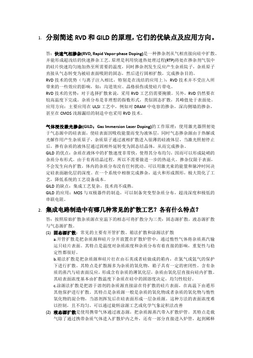
a r X i v :c o n d -m a t /0104490v 1 [c o n d -m a t .m t r l -s c i ] 25 A p r 2001Tiling of the five-fold surface of Al 70Pd 21Mn 9J.Ledieu and R.McGrath ∗Surface Science Research Centre,The University of Liverpool,Liverpool L693BX,UKR.D.DiehlDepartment of Physics,Pennsylvania State University,University Park,PA 16802,USAT.A.Lograsso and D.W.DelaneyAmes Laboratory,Iowa State University,Ames,IA 50011,USAZ.Papadopolos and G.KasnerInstitut f¨u r Theoretische Physik,Universit¨a t Magdeburg,PSF 4120,D-39016Magdeburg,Germany(April 05,2001)The nature of the five-fold surface of Al 70Pd 21Mn 9has been investigated using scanning tunnelling microscopy.From high resolution images of the terraces,a tiling of the surface has been constructed using pentagonal prototiles.This tiling matches the bulk model of Boudard et al.(J.Phys:Cond.Matter 4,10149(1992)),which allows us to elucidate the atomic nature of the surface.Furthermore,it is consistent with a Penrose tiling T ∗((P 1)r )obtained from the geometric model based on the three-dimensional tiling T ∗(2F ).The re-sults provide direct confirmation that the five-fold surface of i -Al-Pd-Mn is a termination of the bulk structure.61.44Br,68.35Bs,82.65-iSince their discovery [1],quasicrystals have extended the boundaries of our knowledge,most strikingly in the redefinition of the crystal undertaken by the Interna-tional Union of Crystallography in 1991[2].The rea-son for this lies in their unusual aperiodic structure,which in the case of i -Al-Pd-Mn and i -Al-Cu-Fe has been described mathematically with reference to a six-dimensional lattice D 6[3,4].The fact that a three-dimensional atomic model [3,4]can be based on a three-dimensional tiling projected from the D 6lattice [5]leads us to expect the five-fold planes of the model to be related to a two-dimensional Penrose-like tiling [6,7].The unusual tribological behavior observed for qua-sicrystals raises questions concerning the nature of their surfaces [8].Systematic studies by Gellman and coworkers indicate that the static friction coefficient for i -Al-Pd-Mn (on itself)is lower than that of most pure metals,and the slip-stick behavior commonly observed on crystalline surfaces is not present [9].A complete un-derstanding of these observations requires a knowledge of the quasicrystal surface structure [10].It can not be assumed a priori that a quasicrystal surface is aperiodic itself or that it reflects a perfect truncation of the bulk structure.If this is the case,however,we would expectthe structure of that surface to reflect the symmetry of a two-dimensional Penrose tiling [5–7].Until now,how-ever,this direct link between theory and experiment has not been made.This is partly because the aperiodic nature of qua-sicrystals makes it difficult to determine their surface structure.Surface diffraction techniques can not be ex-ploited to achieve a full structural determination as they rely on a formalism developed largely for periodic struc-tures [11,12].Scanning probe microscopies offer an alter-native,but even with these methods atomic resolution has so far proved elusive.It has been variously suggested that this is an inherent limitation of the electronic struc-ture of these surfaces [13]or a consequence of defect-like protrusions observed in all studies to date [13–16].In pre-vious work,we introduced an approach based on tiling of scanning tunnelling microscopy (STM)images using regions of high contrast as vertices [15].Though this approach produced partial tilings,the presence of large protrusion defects on the surface introduced breaks in the tiling and comparison with models of the surface was not possible.In this study we carry this tiling approach to fruition,using a combination of experimental and theoretical methods.A refined surface preparation technique has led to terraces which are free from the protrusions found in previous STM studies [13–16].This in turn has led to better resolution STM images which together with the structural perfection,allows us to derive an experimen-tal tiling over a lateral range of ∼100˚A .By comparison with the experimentally derived bulk model of Boudard et al.[17],we identify possible structural entities on the surface.We also demonstrate that the experimen-tal tiling matches the two-dimensional tiling T ∗((P 1)r ),derived from a well established geometric model of the bulk [3,4].The quasicrystal sample was grown using the Bridg-man method and polished using 6µm,1µm and 0.25µm diamond paste on Texmet cloth for one hour.The ultra-high vacuum (UHV)preparation consisted of five sput-ter/anneal cycles.The sputtering angle was at grazing incidence (20◦-30◦);Ar gas was used at 500eV and each sputter lasted 90minutes.Each annealing was to 970K for 120-150minutes.After this procedure,the LEED pattern had five-fold rotational axes and exhibited a low background,with sharp peaks.We note that this temper-ature is at the upper endof the range known to produce quasicrystalline surfaces [18].FIG.1.(a)100×100˚A 2high resolution STM image of a flat terrace (V =1V,I =0.3nA).A pentagonal hole (circled)and a pentagon have been outlined.(b)50×50˚A 2high res-olution STM image (V =1V,I =0.3nA).Several pentagons have been outlined.A Fast Fourier Transform (FFT)of the image in (b)is shown as an inset.This preparation procedure leads to very large flat ter-races (up to 1500˚A wide).Images from the terraces were then obtained which display a higher resolution than those in any previously published STM work [13–16].Fig.1(a)shows a 100×100˚A 2image of a flat terrace with features of atomic size (2-3˚A ).The corrugation across the terraces (see Fig.1(a))is <1˚A .Large areas of the terraces are found without any protrusions,which allows the tip to scan the surface more closely leading to improved resolution.Pentagonal areas of dark contrast (‘holes’)are observed as in previous work [13–16]but now with much improved definition -see the circled area in Fig.1(a).A Fast Fourier Transform (FFT)(inset on Fig.1(b))shows apparent ten-fold symmetry,consistent with a five-fold quasicrystalline surface.Autocorrelation patterns from such images (not shown)reveal ten-fold symmetry and a high degree of order.A notable feature of the surface is that areas of bright contrast may be joined by lines to form regular pen-tagons,with edges of length 8.0±0.3˚A .One such pen-tagon is outlined in Fig.1(a).Using these pentagons as basic building blocks we then construct a tiling of the surface.This procedure is illustrated in Fig.1(b)on a 50×50˚A 2image of the surface.Starting with the pentagon labelled (1),we look for pentagons sharing edges which also have areas of bright contrast at their vertices.In this way,a tiling of the surface can be constructed as shown in Fig.2.Within this patch,the acute rhombus,crown and pentagonal star tiles then appear naturally in addition to the pentagonal tiles.This tiling has the appearance of the Penrose tiling (P1)[7].We estimate that 93%of the 119vertices of the tiling patch coincide with areas of higher contrast;of the remaining 7%which coincide with darker areas the majority are on the perimeter of the tiling where any built-in strain due to slight mismatch will be maximum.Another possibility is the presence of vacancy defects (common on metal surfaces),although a slight distortion of the image toward the top edge due to piezo drift cannot be excluded.FIG.2.Tiling of Fig.1(a)derived as described in the text.This tiling is not necessarily unique,and the tiles them-selves contain internal structure;but this is precisely what is to be expected for this surface,as can be shown by comparison with the experimentally derived model of Boudard et al.,based on x-ray and neutron scattering measurements[17].Fig.3(a)shows one plane from this model,which contains only aluminum atoms.The exper-imentally derived tiling of Fig.2is shown superimposed on this plane without scaling.Fig.3(b)shows that within the pentagons described above,other atoms are also ex-pected to be present,which in turn will give rise to high contrast areas within the pentagons on the STM images. This is demonstrated in Fig.3(c)[17].FIG.3.(a)Experimentally constructed tiling of Fig.2su-perimposed on a plane of the model of Boudard et al.(b) corresponds to a20×20˚A2region of this plane.(c)repre-sents a20×20˚A2region of Fig.1(a).The close correspondence of the experimentally derived tiling with the surface termination of the Boudard model allows us to speculate on the structure of the atomic units on the surface.The plane from the Boudard model con-sists entirely of Al atoms,suggesting that the surface measured is Al-rich.This is in agreement with the re-sults of LEED[11,12].Recent LEIS measurements of the surface[19]have identified a characteristic distance of7.5±0.1˚A;our results suggest that this corresponds to the Al-Al distance along the edges of the pentagons. We now show that this tiling is also contained within the Katz-Gratias-Elser geometric model[3,4].The geo-metric model consists of the three-dimensional quasicrys-talline tiling T∗(2F)derived from a six-dimensional lat-tice,face-centered hypercubic lattice D6.This tiling is decorated by Bergman(and automatically Mackay)poly-topes to give the atomic positions[5].All of the ver-tices of the T∗(2F)tiling can be embedded in a sequence of planes orthogonal to afive-fold symmetry axis of anicosahedron[20].In some of these planes a quasiperiodic tiling T∗(A4) appears([20]and refs.therein).The prototiles inT∗(A4)are golden triangles.The edges of the triangles in the tiling are parallel to the two-fold symmetry axesof an icosahedron(“two-fold directions”)and are of two lengths related by the golden ratioτ.As an intermediate step,we locally derive the tiling T∗with pentagon,acute rhombus and hexagon as prototiles from the quasilattice of the tiling T∗(A4),as shown in Fig.4(left side).The tiling has an inflation factorτ.FIG.4.Left side:The tiling T∗of the plane by the acute rhombus,pentagon and hexagon,locally derived from T∗(A4). Centre:The construction of the tiling T∗((P1)r).Right side: The tiling T∗((P1)r)without the content of the golden trian-gles.Keeping all acute rhombuses from the tiling T∗,we re-place each hexagon by two overlapping pentagons.Now we randomly choose one of the pentagons from each over-lapping pair,and unify the rest of the hexagon(s)with the neighboring acute rhombus.This process is indicated by an arrow in the centre section of Fig.4.In this way we obtain either a crown or a pentagonal star to replace the rhombus,and the result is a tiling T∗((P1)r),see the right-hand side of Fig.4.The tiling T∗((P1)r)is a partly random variant of the Penrose(P1)tiling,T∗(P1)[7,21]. The tiling T∗((P1)r)clearly matches the geometry of the experimentally derived tiling shown in Fig.2.We now compare the edge-length of the tiles to the experi-mental value of8.0±0.3˚A.The scaling for the tilings de-rived above from the model is implicit from previous work [20,22]:the edges of the tilings T∗(A4),T∗,and T∗((P1)r) are of length12.553˚A.However by an investigation of the window in perpendicular space I E⊥of the atomic positions for the plane in the model which we estimatemost closely corresponds to the experimental one we may show that the minimal edge length for a P1(r)tiling isτ−112.553˚A=7.758˚A.Therefore within the geometric model,in a plane that corresponds to that of Fig.2,atiling such as in Fig.4exists with an edge length7.758˚A,in excellent agreement with the experimental obser-vations.Our data and analysis provide dramatic confirmation of the bulk termination of this surface which has been suggested by other workers.The LEED analysis of Gierer and co-workers indicated that the surface is consistent with the bulk quasicrystallinity and is an Al termina-tion[11,12].X-ray photoelectron diffraction(XPD)stud-ies are also consistent with a quasicrystalline surface nature[23].Previous scanning tunnelling microscopy (STM)studies have all presented similar images of the quasicrystalline surface[13,14]having a lower resolu-tion than those presented here(the degree of resolution can be put on a quantitative basis using radial distribu-tion functions(RDF)from autocorrelation patterns(not shown)).Shen et al.,using an autocorrelation analysis showed that the surface structure is consistent with a bulk structure based on truncated pseudo-Mackay icosa-hedra or Bergman clusters[13].Schaub etal.[14]inter-preted their STM images in terms of an Ammann penta-grid model with Fibonacci relationships between struc-tural elements within the terraces and across steps on the ter,these measurements were shown to be in correspondence with the Katz-Gratias-Elser geometric model[3,4]for the atomic positions[20,22].However the lower resolution of these measurements precluded their analysis using the tiling approach described in this pa-per.The ability to prepare surfaces having the structuralperfection observed here will facilitate the precise char-acterization of ordered molecular adsorption,friction and adhesion on quasicrystal surfaces.In previous work on the adsorption of C60molecules of the i-Al-Pd-Mn surface,although local areas were found in which the molecules had Fibonacci scaling relationships,on a larger scale the correlation was broken by the presence of de-fects[24].Surfaces of the quality described above should enable the formation of better ordered overlayers.To summarize,very high resolution STM images offlat terraces of thefive-fold Al70Pd21Mn9surface have been presented.A tiling of the surface based on pentagons of edge8.0±0.3˚A has been experimentally derived.This tiling is shown to be consistent with the geometric model based on the T∗(2F)tiling,and with the experimentally derived model of Boudard et al.[17].These results point clearly to a bulk termination of this surface and lend support to the bulk models of this complex material. The EPSRC(Grant numbers GR/N18680and GR/N25718),NFS(Grant number DMR-9819977)and DFG(Grant number KA1001/4-2)are acknowledged for funding.。