安桥CR-305FX功放图纸
功率放大器电路图及其原理

一、O PA300放大电路OPA300放大电路功能说明:通过设定电阻R4=3R3 来设定该放大器的放大倍数为四倍,即Vout=(1+Rf / R) Vin ,将VCA810的输出信号放大到能满足检波需要的信号。
二、高栅负压的电子管功放电路图下图中R3既是前级的直流负载电阻。
又是给后级提供栅负压的偏值电阻。
它适用于栅负压较高的功率管制作的功放电路。
电路比较简单。
电路中两个竹子的灯丝接地端。
应接在各自阴极电阻的下端。
同样要求电源变压器有两个灯丝绕组,功率级与前级的灯丝分别供电。
电路是用6Pl做的实验,虽然栅负压较低,但工作很正常,说明电路是成功的。
同样要注意的是:一定要在插上前级管子后再开电源,否则不能加电。
三、推挽式功率放大级的正偏压电路此电路用EL34管。
在两只功放管阴极电路中串入一只50Ω左右的线绕电位器或半可变线绕电阻,中点接地即可。
调整电位器W使两管的阴极电压平衡、对称,再放音就会有出色的表现。
正偏压的方式也可以用在ABI类自给偏压的推挽式功率放大级中。
四、AD8656双运放芯片组成的接收放大电路使用AD8656双运放芯片组成接收放大电路。
该运放适合+2.7~+5.5 V电源电压供电,是具有低噪声性能的精密双运算放大器。
AD8656型CMOS放大器在满共模电压(VCM)范围内提供250 mV精密失调电压最大值,且在10 kHz处提供低电压噪声谱密度和0.008%的低真,无需外部三极管增益级或多个并行的放大器以减小系统噪声。
通过干电池提供3V单电源供电,接收放大电路如图2所示。
放大电路由AD8656进行两级放大,抵消线圈所感应到的信号电压幅值因距离的增加而产生的衰减,放大所接收到的微弱信号,增加无线传输距离。
系统接收电路经D8656放大后的输出电压输至单片机进行A/D转换,对数据进行编解码,而未采用检波解调电路,可有效简化电路结构。
五、高频信号放大电路的性能比较分析一、高频管(UHF)9018fTl00(MHz)的信号放大电路电视高频头输出的第一中频信号和音频信号通过高频管9018放大后也确有显效。
简单音频功放电路原理图大全(六款简单音频功放电路设计原理图详解)
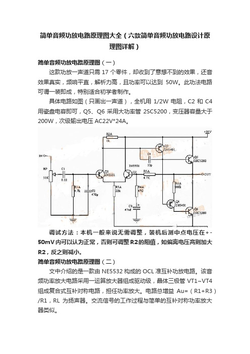
简单音频功放电路原理图大全(六款简单音频功放电路设计原理图详解)简单音频功放电路原理图(一)这款功放一声道只需17个零件,却收到了意想不到的效果,还音效果真实,频响平直,解析力高,且功率可以达到50W。
此功法电路可谓一装即成,特别适合初学者制作。
具体电路如图(只画出一声道),全机用1/2W电阻,C2和C4用瓷盘电容即可,Q5、Q6采用大功率管2SC5200,变压器容量大于200W,次级输出电压AC22V*24A。
调试方法:本机一般来说无需调整,装机后测中点电压在+-50mV内可以认为正常,否则可调整R2的阻值,如偏离电压高则加大R2,反之则减小。
简单音频功放电路原理图(二)文中介绍的是一款由NE5532构成的OCL准互补功放电路。
该音频功率放大电路采用一运算放大器组成驱动级,晶体三极管VT1~VT4组成复合式互补对称电路,担任功率放大。
电路总增益Au=(R1+R3)/R1,RL为扬声器。
交流信号的工作过程与简单的互补对称功率放大器类似。
其中电位器RP1调节整机的增益,RP2用于调整中点电压。
本电路经过简单的调试即可成功,更换不同的运放整机的音色都会随之改变,DIY的乐趣尽在其中。
缺点是功率较小,可以把运放的供电提高并稳压在正负15V,后级功放管的电压提高到正负30V以上,即可满足一般家庭使用的需要。
简单音频功放电路原理图(三)LM4889是一款主要应用于手机的音频功率放大器。
5V电源时,它能够提供1瓦的连续平均功率输出(8Ω桥式连接负载),失真小于2%(THD+N)。
LM4889需要的外部元件极少,不需要输出耦合电容器或启动电容器,因此适合移动电话和其他低电压应用。
该LM4889具有低功耗的停机模式、内部误关断保护机制、噪音消除功能,可以配置外部的增益设定电阻。
LM4889典型应用电路:简单音频功放电路原理图(四)LM380集成音频功率放大器的应用电路如下图所示:简单音频功放电路原理图(五)OPA541芯片是一个功率放大器,它能由最大为士40V的电源供电,而产生最大电流为5A的连续输出。
安桥tx-sr674和604功放说明书

RC-651M
Ct-16
Ct-17
• •
•
•
V
L
R
Ct-18
PRE OUT
LINE INPUT
LINE INPUT
SUB WOOFER
1 2 3 4 2 3 4
1
5
6
5
6
7
8
7
8
Ct-19
•
1
5/8" (15 mm)
c
Ct-25
7.1 ch 5.1 ch
FRONT L SURROUND CENTER SURR BACK L
R DVD SUB WOOFER
R
L FRONT
R
L SURROUND
R CENTER SUB WOOFER
L SURR BACK
R
Ct-26
A
B
C
a
b
c
• •
a
a b b a c c
A B C a b c
RETURN
SETUP
E
LISTENING MODE STEREO SURROUND
AUDIO SUBTITLE RANDOM REPEAT TEST TONE CH SEL PLAY MODE LEVELLEVEL+
J K L
F
DISPLAY VCR
L NIGHT DVD
CINE FLTR HDD
RECEIVER
ON/STANDBY
ZONE2
REMOTE MODE
ON/STANDBY
1
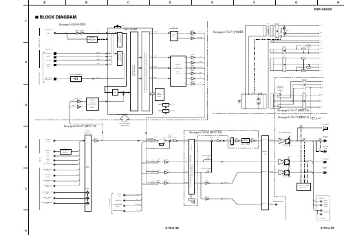
雅马哈DSP-AX620功放图纸
IC303A 1/7
IC303E
FRONT MIX IC302B 3/5
IC316
IC501 5/3 7/1
TUNER (L/R)
3/5
TONE CONTROL
IC502 6/4
RY102 8/2 Q303, 304 LO/RO
SW351
MAIN A (L/R)
PA
Q110A/C Q114A/C -B SW351
0 0 0
0 0.1 4.1 4.9 0 0
0
1A 1 1Y 2
14 VDD 13 6A 12 6Y 11 5A 10 5Y 9 4A 8 4Y
7 5
FL/FR
0 0
6
4.9 2.5 4.9 2.5
4.9
IC808 : TC74HCUO4AF-TP1 Hex Inverters
1.7 1.6 4.0 0 3.4 3.4
0 3.9 0
3 1 0.3 2
3.4 4.7 4.6 0.3 0.1 4.8 4.8 4.8 3.9 0 3.9 3.9 0 2.5 3.6 0
A1 1 B1 2
14 VDD
4.9
13 B4 12 A4 11 Y4 10 B3 9 A3 8 Y3
5
0 3.9
DVD DIGITAL
5 4
1.7 1.7 1.7 0 0 0 2.5 0
A
B
C
D
E
F
G
DSP-AX620
H
s BLOCK DIAGRAM
1
See page E-68/J-66 (DSP)
1 T741 XL801 2 D743-746 S12
300W音频功放电路图(四款300W音频功放电路图详解)

300W音频功放电路图(四款300W音频功放电路图详解)描述一.300W音频功放电路图选用MJL4281A(NPN)和MJL4302A(PNP),具有高带宽,良好的SOA(安全工作区),高线性和高增益。
驱动晶体管选用MJE15034(NPN)和MJE15035(PNP)。
所有器件的额定电压为350V。
输出三极管选用MJL4281A(NPN)和MJL4302A(PNP),具有高带宽,良好的SOA(安全工作区),高线性和高增益。
驱动晶体管选用MJE15034(NPN)和MJE15035(PNP)。
所有器件的额定电压为350V。
性能指标:8Ω4Ω电压增益27dB27dB功率(连续)153W (240W)240W (470W)峰值功率 - 10 ms185W (250W)344W (512W)峰值功率 - 5 ms185W (272W)370W (540W)输入电压1.3V (2.0V)RMS1.3V (2.0V) RMS噪声 *-63dBV (ref. 1V)-63dBV (ref. 1V)S / N比 *92dB92dB失真0.4%0.4%失真(@ 4W)0.04% (1 Khz)0.04% (1 Khz)失真(@ 4W)0.07% (10 kHz)0.07% (10 kHz)摆率》 3V/us》 3V/us300W音频功率放大器电路原理图300W音频功率放大器电源线路图二.由STK3152Ⅲ组成的300W功放电路前置放大电路信号输入采用平衡与不平衡两种方式,平衡输入电路由运放NE5532及外围电路组成,不平衡输入直接送人STK3152Ⅲ的1脚和15脚,经STK3152Ⅲ放大后的信号分别由5、6、10、11脚输出,2、14脚分别为两个声道的负反馈输入端NF。
电源电路功率放大电路每声道采用了8对日本东芝生产的发烧级大功率对管,以保证足够的电流驱动能力。
制作时也可根据实际需要选取合适的功率管数量。
图8对应的印板图见图9。
ELACE-305经典音箱拆解研究
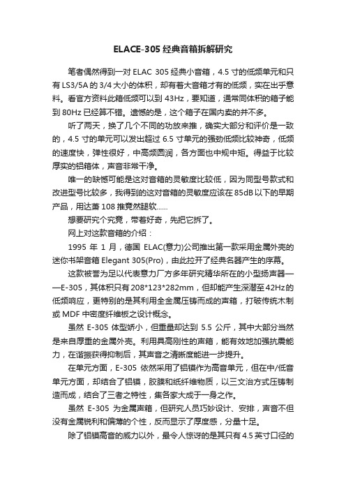
ELACE-305经典音箱拆解研究笔者偶然得到一对ELAC 305经典小音箱,4.5寸的低频单元和只有LS3/5A的3/4大小的体积,却有着大音箱才有的低频,实在出乎意料。
看官方资料此箱低频可以到43Hz,要知道,通常同体积的箱子能到80Hz已经算不错。
遗憾的是,这个箱子在国内卖的并不多。
听了两天,换了几个不同的功放来推,确实大部分和评价是一致的,4.5寸的单元可以发出超过6.5寸单元的强劲低频比较神奇,低频的速度快,弹性很好,中高频圆润,各方面也中规中矩。
得益于比较厚实的铝箱体,声音非常干净。
唯一的缺憾可能是这对音箱的灵敏度比较低,因为同型号款式和改进型号比较多,我得到的这对音箱的灵敏度应该在85dB以下的早期产品,用达萧108推竟然腿软......想要研究个究竟,带着好奇,先把它拆了。
网上对这款音箱的介绍:1995年1月,德国ELAC(意力)公司推出第一款采用金属外壳的迷你书架音箱Elegant 305(Pro),由此拉开了经典名器产生的序幕。
这款被誉为足以代表意力厂方多年研究精华所在的小型扬声器——E-305,其体积只有208*123*282mm,但却能产生深潜至42Hz的低频响应,更特别的是其利用全金属压铸而成的声箱,打破传统木制或MDF中密度纤维板之设计概念。
虽然E-305体型娇小,但重量却达到5.5公斤,其中大部分当然是来自厚重的金属外壳。
利用具高刚性的声箱,能有效地加强抗震能力,在谐振获得抑制后,其声音之清晰度能进一步提升。
在单元方面,E-305依然采用了铝镆作为高音单元,但在中/低音单元方面,却结合了铝镆,胶膜和纸纤维物质,以三文治方式压铸制造而成,结合了三者之特性,集各家大成于一身之作。
虽然E-305为金属声箱,但研究人员巧妙设计、安排,声音不但没有金属锐利和偏薄的个性,反而显示了厚度感,分量十足。
除了铝镆高音的威力以外,最令人惊讶的是其只有4.5英寸口径的中/低音单元,能产生令人难以相信之浩瀚低频量感和深潜度,而在庞大音压之下,E-305依然面不改容,闻风不动,单是这份大将之风,足以令不少人对小型扬声器另眼相看。
ONKYO_安桥_TX-DS595_中文说明书
ContentsThank you for purchasing the Onkyo AV Receiver.Please read this manual thoroughly before making connections and plugging in the unit. Following the instructions in this manual will enable you to obtain optimum performance and listening enjoyment from your new AV Receiver. Please retain this manual for future reference.TX-DS595AppendixSpecifications ................................................49Troubleshooting guide.. (50)Remote controllerUsing remote controller.................................34Learning a pre-programming code................38Operating your programmedremote controller......................................40Programming the commands of remote controllers for other devices into the remote controller.....42Using a Macro function (45)Setup and operationSpeaker setup.................................................19Listening to Radio Broadcasts.......................21Listening to RDS broadcasts(European models only)..........................................23Enjoying music or videos with TX-DS595...25Using listening mode.....................................28Input Setup.....................................................29Preference ......................................................32Recording. (33)Before usingInportant Safeguards........................................2Precautions.......................................................3Features............................................................4Supplied accessories........................................4Before using this unit .. (5)A V ReceiverInstruction ManualFacilities and connectionsFront panel facilities........................................6Remote controller ............................................8Connections ...................................................10Connecting speakers......................................14Connecting the power....................................16Connecting antennas.. (17)1.Read Instructions – All the safety and operating instructionsshould be read before the appliance is operated.2.Retain Instructions – The safety and operating instructionsshould be retained for future reference.3.Heed Warnings – All warnings on the appliance and in theoperating instructions should be adhered to.4.Follow Instructions – All operating and use instructionsshould be followed.5.Cleaning – Unplug the appliance from the wall outlet beforecleaning. The appliance should be cleaned only as recom-mended by the manufacturer.6.Attachments – Do not use attachments not recommended bythe appliance manufacturer as they may cause hazards.7.Water and Moisture – Do not use the appliance near water –forexample, near a bath tub, wash bowl, kitchen sink, or laundry tub; in a wet basement; or near a swimming pool; and the like.8.Accessories – Do not place the appliance on an unstable cart,stand, tripod, bracket, or table. The appliance may fall, causing serious injury to a child or adult, and serious damage to the appliance. Use only with a cart, stand, tripod, bracket, or table recommended by the manufacturer, or sold with the appliance.Any mounting of the appliance should follow the manufacturer’s instructions,and should use a mounting ac-cessory recommended by themanufacturer.9.An appliance and cart combi-nation should be moved withcare. Quick stops, excessiveforce, and uneven surfaces maycause the appliance and cartcombination to overturn.10.Ventilation – Slots and openings in the cabinet are providedfor ventilation and to ensure reliable operation of the appliance and to protect it from overheating, and these openings must not be blocked or covered. The openings should never be blocked by placing the appliance on a bed, sofa, rug, or other similar surface. The appliance should not be placed in a built-in instal-lation such as a bookcase or rack unless proper ventilation is provided. There should be free space of at least 20 cm (8 in.) and an opening behind the appliance.11.Power Sources – The appliance should be operated only fromthe type of power source indicated on the marking label. If you are not sure of the type of power supply to your home, consult your appliance dealer or local power company.12.Grounding or Polarization – The appliance may be equippedwith a polarized alternating current line plug (a plug having one blade wider than the other). This plug will fit into the power outlet only one way. This is a safety feature. If you are unable to insert the plug fully into the outlet, try reversing the plug. If the plug should still fail to fit, contact your electrician to replace your obsolete outlet. Do not defeat the safety purpose of the polarized plug.13.Power-Cord Protection – Power-supply cords should berouted so that they are not likely to be walked on or pinched by items placed upon or against them, paying particular attention to cords at plugs, convenience receptacles, and the point where they exit from the appliance.14.Outdoor Antenna Grounding – If an outside antenna or cablesystem is connected to the appliance, be sure the antenna or cable system is grounded so as to provide some protection against voltage surges and built-up static charges. Article 810 of the National Electrical Code, ANSI/NFPA 70, provides in-formation with regard to proper grounding of the mast and sup-porting structure, grounding of the lead-in wire to an antenna-discharge unit, size of grounding conductors, location of an-tenna-discharge unit, connection to grounding electrodes, and requirements for the grounding electrode. See Figure 1.15.Lightning – For added protection for the appliance during alightning storm, or when it is left unattended and unused for long periods of time, unplug it from the wall outlet and discon-nect the antenna or cable system. This will prevent damage to the appliance due to lightning and power-line surges.16.Power Lines – An outside antenna system should not be lo-cated in the vicinity of overhead power lines or other electric light or power circuits, or where it can fall into such power lines or circuits. When installing an outside antenna system, extreme care should be taken to keep from touching such power lines or circuits as contact with them might be fatal.17.Overloading – Do not overload wall outlets, extension cords,or integral convenience receptacles as this can result in a risk of fire or electric shock.18.Object and Liquid Entry – Never push objects of any kindinto the appliance through openings as they may touch danger-ous voltage points or short-out parts that could result in a fire or electric shock. Never spill liquid of any kind on the appliance.19.Servicing – Do not attempt to service the appliance yourself asopening or removing covers may expose you to dangerous volt-age or other hazards. Refer all servicing to qualified service personnel.20.Damage Requiring Service – Unplug the appliance form thewall outlet and refer servicing to qualified service personnel under the following conditions:A.When the power-supply cord or plug is damaged,B.If liquid has been spilled, or objects have fallen into theappliance,C.If the appliance has been exposed to rain or water,D.If the appliance does not operate normally by following theoperating instructions. Adjust only those controls that arecovered by the operating instructions as an improper ad-justment of other controls may result in damage and willoften require extensive work by a qualified technician torestore the appliance to its normal operation,E.If the appliance has been dropped or damaged in any way,andF.When the appliance exhibits a distinct change in perfor-mance – this indicates a need for service.Important SafeguardsPORTABLE CART WARNINGS3125A231.Warranty ClaimYou can find the serial number on the rear panel of this unit. In case of warranty claim, please report this number.2.Recording CopyrightRecording of copyrighted material for other than personal use is illegal without permission of the copyright holder.3.AC FuseThe fuse is located inside the chassis and is not user-serviceable. If power does not come on, contact your Onkyo authorized service station.4.CareFrom time to time you should wipe the front and rear panels and the cabinet with a soft cloth. For heavier dirt, dampen a soft cloth in a weak solution of mild detergent and water, wring it out dry, and wipe off the dirt. Following this, dry immediately with a clean cloth. Do not use rough material, thinners, alcohol or other chemi-cal solvents or cloths since these could damage the finish or remove the panel lettering.5.PowerWARNINGBEFORE PLUGGING IN THE UNIT FOR THE FIRST TIME,READ THE FOLLOWING SECTION CAREFULLY.The voltage of the available power supply differs according to country or region. Be sure that the power supply voltage of the area where this unit will be used meets the required voltage (e.g., AC 230 V, 50 Hz or AC 120 V, 60 Hz) written on the rear panel.Worldwide models are equipped with a voltage selector to conform to local power supplies. Be sure to set this switch to match the volt-age of the power supply in your area before plugging in the unit.For British modelsReplacement and mounting of an AC plug on the power supply cord of this unit should be performed only by qualified service personnel.IMPORTANTThe wires in the mains lead are coloured in accordance with the following code:Blue :Neutral Brown :LiveAs the colours of the wires in the mains lead of this apparatus may not correspond with the coloured markings identifying the termi-nals in your plug, proceed as follows:The wire which is coloured blue must be connected to the terminal which is marked with the letter N or coloured black.The wire which is coloured brown must be connected to the termi-nal which is marked with the letter L or coloured red.IMPORTANTA 5 ampere fuse is fitted in this plug. Should the fuse need to be replaced, please ensure that the replacement fuse has a rating of 5amperes and that it is approved by ASTA or BSI to BS1362. Check for the ASTA mark or the BSI mark on the body of the fuse.IF THE FITTED MOULDED PLUG IS UNSUITABLE FOR THE SOCKET OUTLET IN YOUR HOME THEN THE FUSE SHOULD BE REMOVED AND THE PLUG CUT OFF AND DIS-POSED OF SAFELY. THERE IS A DANGER OF SEVERE ELECTRICAL SHOCK IF THE CUT OFF PLUG IS INSERTED INTO ANY 13 AMPERE SOCKET.If in any doubt, consult a qualified electrician.Precautions(NEC ART 250, PART H)S2898A21.Replacement Parts – When replacement parts are required, besure the service technician has used replacement parts specified by the manufacturer or have the same characteristics as the original part. Unauthorized substitutions may result in fire,electric shock, or other hazards.22.Safety Check – Upon completion of any service or repairs to theappliance, ask the service technician to perform safety checks to determine that the appliance is in proper operation condition.23.Wall or Ceiling Mounting – The appliance should be mountedto a wall or ceiling only as recommended by the manufacturer.24.Heat – The appliance should be situated away from heatsources such as radiators, heat registers, stoves, or other appli-ances (including amplifiers) that produce heat.For U.S. modelsNote to CATV system installer:This reminder is provided to call the CATV system installer ’s at-tention to Section 820-40 of the NEC which provides guidelines for proper grounding and, in particular, specifies that the cable ground shall be connected to the grounding system of the building, as close to the point of cable entry as practical.FCC Information for UserCAUTION:The user changes or modifications not expressly approved by the party responsible for compliance could void the user ’s authority to operate the equipment.NOTE:This equipment has been tested and found to comply with the limits for a Class B digital device, pursuant to Part 15 of the FCC Rules.These limits are designed to provide reasonable protection against harmful interference in a residential installation. This equipment generates, uses and can radiate radio frequency energy and, if not installed and used in accordance with the instructions, may cause harmful interference to radio communications. However, there is no guarantee that interference will not occur in a particular installa-tion. If this equipment does cause harmful interference to radio or television reception, which can be determined by turning the equip-ment off and on, the user is encouraged to try to correct the interfer-ence by one or more of the following measures:•Reorient or relocate the receiving antenna.•Increase the separation between the equipment and receiver.•Connect the equipment into an outlet on a circuit different from that to which the receiver is connected.•Consult the dealer or an experienced radio/TV technician for help.For Canadian modelsNOTE:THIS CLASS B DIGITAL APPARATUS COMPLIES WITH CA-NADIAN ICES-003.For models having a power cord with a polarized plug:CAUTION: TO PREVENT ELECTRIC SHOCK, MATCHWIDE BLADE OF PLUG TO WIDE SLOT, FULLY INSERT.Modele pour les CanadienREMARQUE:CET APPAREIL NUM ÉRIQUE DE LA CLASSE B EST CON-FORME À LA NORME NMB-003 DU CANADA.Sur les mod èles dont la fiche est polaris ée:ATTENTION: POUR ÉVITER LES CHOCSÉLECTRIQUES, INTRODUIRE LA LAME LA PLUS LARGE DE LA FICHE DANS LA BORNE CORRESPONDANTE DE LA PRISE ET POUSSER JUSQU ’AU FOND.FIGURE 1:EXAMPLE OF ANTENNA GROUNDING AS PER NATIONAL ELECTRICAL CODE, ANSI/NFPA 704Supplied accessoriesCheck that the following accessories are supplied with the TX-DS595.AM loop antenna × 1FM indoor antenna × 1(connector will vary depending on model specifications)Remote controller × 1Batteries (AA, R6 or UM-3) × 275/300× 1(For all models other than USA,Canadian and European models)FeaturesI 75 Watts minimum of continuous RMS power to eachof the five channels into 8 Ω from 20 Hz to 20 kHz with no more than 0.08% THD (USA models, FTC rating)I 110 Watts minimum of continuous RMS power toeach of the five channels into 6 Ω at 1 kHz (European models, DIN)I 140 Watts minimum to each of the five channels into6 Ω at 1kHz (Asian models, EIAJ)I Wide Range Amplifier Technology (WRAT)I Extended Frequency Response (10 Hz to 100 kHz)I Optimum Gain Volume CircuitryI Dolby ®* Digital, DTS ®, Dolby Pro Logic II decoding I A-Form Listening Mode MemoryI Non-Scaling Configuration I Cinema Re-EQ TMI Late night mode (high, low, off)I 5.1-Channel inputI 4 Assignable digital inputs (2 coaxial, 2 optical)I Smart Scan Navigator with LEDs I 40 FM/AM random presets I IntelliVolumeI Powerful programmed/learning remote with macrosand mode-key LEDs*Manufactured under license from Dolby Laboratories.“Dolby ”, “Pro Logic ” and the double-D symbol are trademarks of Dolby Laboratories. Confidential Unpublished Works. ©1992-1997 Dolby Laboratories, Inc. All rights reserved.•Re-Equalization and the “Re-EQ ” logo are trademarks of Lucasfilm Ltd.Manufactured under license of Lucasfilm Ltd.•Manufactured under license from Digital Theater Systems, Inc. US Pat.No.5,451,942 and other worldwide patents issues and pending. “DTS ”and “DTS Digital Surround ” are trademarks of Digital Theater Systems,Inc.© 1996 Digital Theater Systems, Inc. All rights reserved.5Installing the remote controller batteries1.Remove the battery compartment cover by pressingand sliding the cover.2.Insert two AA (R6 or UM-3) batteries into the batterycompartment. Carefully follow the polarity diagram (positive (+) and negative (–) symbols) inside the battery compartment.3.After batteries are installed and seated correctly,replace the compartment cover.Before using this unitSetting the Voltage selector (Worldwide models only)Worldwide models are equipped with a voltage selector to conform with local power supplies. Be sure to set this switch to match the voltage of the power supply in your area before plugging in the unit.Determine the proper voltage for your area: 220-230 V or 120 V.If the preset voltage is not correct for your area, insert a screwdriver into the groove in the switch. Slide the switch all the way to the upper (120 V) or to the lower (220-230 V), whichever is appropriate.Notes:•Do not mix new batteries with old batteries or different kinds of batteries.•To avoid corrosion, remove the batteries if the remote controller is not to be used for a long time.•Remove dead batteries immediately to avoid damage from corrosion. If the remote controller does not operate smoothly,replace both the batteries at the same time.•The life of the batteries supplied is about six months but this will vary depending on usage.Using the remote controllerPoint the remote controller toward the remote control sensor. The STANDBY indicator lights up when the unit receives a signal from the remote controller.Notes:•Place the unit away from strong light such as direct sunlight or inverted fluorescent light which can prevent proper operation of the remote controller.•Using another remote controller of the same type in the same room or using the unit near equipment which uses infrared rays may cause operational interference.•Do not put objects on the remote controller. Its buttons may be pressed by mistake and drain the batteries.•Make sure the audio rack doors do not have colored glass.Placing the unit behind such doors may prevent proper remote controller operation.•If there is any obstacle between the remote controller and the6Front panel facilitiesHere is an explanation of the controls and displays on the front panel of the TX-DS595.Front panelFront panel displaySpeakers A/B indicatorsSleep indicator Multi function displayListening mode or digital input format indicatorsTuning indicators7Front panel facilitiesFor operational instructions, see page indicated in brackets [ ].Turns on and off the main power supply for the TX-DS595.Lights when the TX-DS595 is in the standby state and flashes whena signal is received from the remote controller.Press to turn on the TX-DS595 when in the standby state. Press againto return the TX-DS595 to the standby state.Press these buttons to turn on and off speakers systems A and B.Press to select the channel whose level is to be adjusted.The MASTER VOLUME dial is used to control the volume.To listen with headphones, plug a pair headphones with a standard stereo plug into the PHONES jack on the TX-DS595 front panel.When you connect headphones, the unit will enter STEREO mode automatically and no sound will be heard from the speakers. If you have selected MULTI CH INPUT, you will hear sound only from the FRONT L and R channels. Note that the volume level for theheadphones is adjustable.This button is used to select the type of audio input signal. Each time pressed, the setting cycles from “AUTO ” → “MULTICH ” →“ANALOG ”and back.AM, PHONO, and CD) [25]These buttons are used to select the input source.Boosts or cuts the bass response. Bass adjustment is effective onlyfor the front speakers and headphones.Boosts or cuts the treble response. Treble adjustment is effectiveonly for the front speakers and headphones.[19, 20, 22, 24-27, 30-32]Used to make settings in the setup display, change listening modesettings, and more.Press to enter and exit the setup mode.Press to move up one level in the setup mode.The DISPLAY button is used to display information about the current input source signal. Each time you press the display button,the screen changes to show you different information concerning theinput signal.This button is only available on European models. Use this button to help tune into the Radio Data System (RDS) for FM broadcasting.RDS was developed within the European Broadcasting Union (EBU) and is available in most European countries. Each time the button is pressed, the display changes from RT (radio text) to PTY(program type) to TP (traffic program) and then back to RT again.Press to set the brightness of the front display. There are 3 settingsavailable: normal, dark, and very dark.When there is too much noise in the stereo reception of an FMbroadcast, press to turn off the FM MUTE function.This button is used to assign the radio station that is currently tuned in to a preset channel or delete a previously preset station.Use these buttons to change the tuner frequency. The tuner frequency is displayed in the front display and it can be changed in 50 kHz increments for FM and 10 kHz (or 9 kHz) increments for AM.When FM is selected, you can hold down one of the tuning buttons and then release it to activate the auto-search feature. It will search for a station in the direction of the button you pressed and stop when it tunes into one.When AM or FM is selected as the input source, press one of these buttons to jump to a radio station that you preset using the PRESET MEMORY button. Pressing the right button moves from the most recently preset station to older ones, and pressing the left button moves in the reverse order.Remote controllerThis indicator acts as a guide when commands are programmed intoor sent by the remote controller. It also warns the user when an erroris made or battery power is low.ON: Turns on the TX-DS595.STDBY: Places the TX-DS595 in the standby state.Be aware that pressing the STDBY button only places the TX-DS595 in standby and does not turn the power completely off.Sets the sleep function.The SLEEP button enables you to set the TX-DS595 to turn offautomatically after a specified time period.For executing and programming the Direct Macro function.For selecting the component to be operated by the remote controller.When a MODE button is pressed, it will light green for 8 seconds.The selected MODE button will also light whenever any otheroperation button is pressed to tell you which mode the remotecontroller is in.Press to move up one level in the setup mode.When in the RCVR mode, for selecting a tuner preset channel.For selecting the disc to be played back for components with discchangers when in the DVD or CD modes.CH SEL: For selecting the speaker for level adjustment when in theRCVR mode. Used together with the LEVEL / buttons.TOP MENU: When in the DVD mode, for displaying the menuscreen(s) recorded on DVD media.AUDIO: For selecting the audio input signal. The setting changesfrom “AUTO” to “MULTICH” to “ANALOG” and back each timethis button is pressed.TV/VCR: Must be preprogrammed for use in the TV and VCRmodes.LEVEL /: Select the speaker whose volume is to be adjustedusing the CH SEL button and adjust the volume using the LEVEL /buttons in the RCVR mode. [9, 27]ANGLE: When in the DVD mode, for selecting a camera anglewhen a DVD-Video is recorded with multiple angle playback. [36]SUBTITLE: When in the DVD mode, for selecting one of thesubtitle languages recorded on a DVD-Video. [36]For operating Onkyo components connected to the TX-DS595.89Remote controllerSelects an input source.Same as the input selector buttons on front panel of the TX-DS595.The input source for each buttons is given here. DVD:DVD, CD:CD,V1:VIDEO1, V2:VIDEO2, V3:VIDEO3, V4:Not used with the TX-DS595, T1:TAPE, T2:Not used with the TX-DS595, TUN:FM/AM,PH:PHONO.Re-EQ/DISPLAY/DIMMER buttons1 to 9, +10, --/---, 0: For entering the number of a track.STEREO, DIRECT, DSP /, SURR, A.ST: You can select a listening mode. [25, 28]STEREO: Changes the listening mode directly to the Stereo listening mode. If pressed, the listening mode for the selected input source set in the Listening Mode Preset is also changed to the Stereo listening mode.SURR (Surround): Changes the listening mode to the surround mode for the current input signal (e.g., Dolby Pro Logic II,Dolby Digital, or DTS). If pressed, the listening mode for the selected input source set in the Listening Mode Preset is also changed to the Surround listening mode.For Dolby Pro Logic II, this button also changes the mode between Dolby Pro Logic II Movie and Dolby Pro Logic II Music.DIRECT: Changes the listening mode directly to the Direct listening mode. If pressed, the listening mode for the selected input source set in the Listening Mode Preset is also changed to the Direct listening mode.A.ST (All Channel Stereo): Changes the listening mode directly to the Stereo listening mode. If pressed, the listening mode for the selected input source set in the Listening Mode Preset is also changed to the All Channel Stereo listening mode.DSP /: Changes the listening mode as shown below.Direct ↔ Stereo ↔ Surround ↔ Orchestra ↔ Unplugged ↔Studio-Mix ↔ TV Logic ↔ All Ch Stereo ↔ Direct.If pressed, the listening mode for the selected input source set in the Listening Mode Preset is also changed.Re-EQ: Depending on the listening mode, you can turn the cinema re-equalization function on or off. [25]Re-EQ (re-equalization) takes the edginess or “brightness ” out of your home cinema sound to compensate for the fact that sound mixed for theaters may sound too bright when played back through speakers in the home environment.On: Select to turn on the re-equalization filter.Off: Select to turn off the re-equalization filter.Note:The Re-EQ function is effective on the Dolby Pro Logic II Surround and Dolby Digital Surround.SP A, SP B: For turning on and off speakers systems A and B. [26]DISPLAY:For changing the display in the front display. [26]DIMMER: Adjusts the display brightness.There are three settings available: normal, dark and very dark.For executing and programming the Macro function.Press to enter and exit the setup mode.For selecting and entering settings in the setup mode.For adjusting the volume.TEST: Outputs a test tone for setting speaker levels.Use this button in conjunction with the LEVEL / and CH SEL buttons to calibrate the speakers levels.1.Press the TEST button.A test sound (pink noise) will be heard from the left front speaker. At this point, it is not necessary to adjust the volume of the test sound.2.Press the CH SEL button.The test sound will now be heard from a different speaker.e the LEVEL / buttons to adjust the volume of the test sound from this speaker to the same level that you heard from the previous speaker.4.Repeat the procedure in step 2 and 3 until the volume of the test sound from all speakers is the same level.Each time you press the CH SEL button, the test sound will be heard from a different speaker. The speaker order for calibration is front left → center → front right → surround right → surround left → subwoofer.5.Press the TEST button to exit the setting.For a more detailed explanation of how to calibrate the speaker levels, see page 20.MENU: When in the DVD mode, this button displays the DVDmenu.Activates the mute function.ZONE 2: Not used with the TX-DS595.SEARCH: When in the DVD mode, for finding the specific section on a disc where you want to start playback.ENTER: When in the MD mode, for confirming the selection.10ConnectionsHere is explanation of how to connect the main components to the TX-DS595 in the standard manner. There are many ways that any one component can be connected, and it is up to you to decide which method best fits your situation. The directions given here are only one option and should only be thought of as such. It is best to fully understand the nature of each connector and terminal as well as each of your components and their features to ascertain which method of connection is best.•Be sure to always refer to the instructions that came with the component that you are connecting.•Do not plug in the power cord until all connections have been made.•For input jacks, red connectors (marked R) are used for the right channel, white connectors (marked L) are used for the left channel, and yellow connectors (marked V) are used for video connection.•Do not bind audio/video connection cables with power cords and speaker cables. Doing so may adversely affect the picture and sound quality.•When using the digital inputs, make sure to also connect theanalog connections whenever possible.•Insert all plugs and connectors securely. Improper connections can result in noise, poor performance, ordamage to the equipment.•When using one of the optical input jacks, remove the protective cap and keep it safely. When the jack is not used,replace the protective cap.•When using an optical input jack, always use an optical fiber cable.Optical digital input terminalAn optical digital input terminal is equipped with a protection cap. When connecting,remove this cap. When not using, put the cap back on the terminal.Connecting your video Default setting Input source Digital input MultichannelDVD COAX 1Yes VIDEO 1COAX 2No VIDEO 2----No VIDEO 3OPT 2No VIDEO 4----No TAPE ----NoFM AM PHONO ----No CDOPT 1NoCOAX: Coaxial OPT: Optical ----: No setting : Not applicable。
无图纸情况下专业功放的维修(图)
无图纸情况下专业功放的维修(图)专业功率放大器在销售时只给使用说明,不附电路原理图。
专业功放要达到足够的功率,其正负供电电压都在60V~90V之间。
而家用功放虽然标称100W或更大的功率,其供电电压只在25V~45V之间。
工作电压高了,出故障时损坏的程度和范围就加深加大了。
有些维修人员在初次维修专业功放时,像修家用功放一样只换上几个大功率管就开机送电.结果放炮冒烟新管又烧坏。
笔者从实践中总结了一些经验。
提供给同行作参考。
一、参考草图了解电路专业功率放大器多采用OCL电路,在使用时都与调音台配合,没有家庭影院功放复杂的杜比解码、卡拉OK、音调调整等前置电路,是纯后级功率放大器,分析电路就容易一些。
在分析电路前先画一张如图1的草图,它是OCL电路基本结构图。
虽然各种功放电路各有千秋,但基本上是由图中几部分组成。
差动输入有单差动和双差动之分(也有采用运算放大器输入电路的)。
差动管发射极恒流源种类较多,常见有稳压二极管和三极管组成的恒流源和两个三极管组成的镜流源。
双差动没有图中双线框内部分,单差动则取掉NPN管一路差动,增加双线框内射随电路。
电压放大级各种功放基本一样。
电流放大又称推动级,包括恒压偏置电路,各种功放也基本一样。
功率输出级一般专业功放部采用多管并联,并管多少随机而异。
保护电路有过流保护和扬声器保护,不少机型还有温度保护,虽然保护电路各具特色,但故障率较低,对功放主电路维修影响不大。
二、顺藤摸瓜对号入座大概了解OCL电路的构成后,就可对功放主板进行分析了,一般专业功放左右声道分成两块板,电路完全一样(因通风散热结构不同,部分机型两块板元件布局不一样)。
顺大功率管基极找出推动管,推动管多采用中功率对管。
恒压偏置管因温度补偿多靠在散热片上。
顺推动管基极找电压放大管。
音频信号输入插座经阻容所接的是差动输入级。
这样顺藤一摸,一张待修功放的电路图就浮现在眼前。
三、检查电路尽除坏件专业功放的损坏多因使用不当所致,如长时间超负荷工作或话筒自激啸叫等。
接头焊接图
1.RCA
RCA莲花接头---用于音频和视频信号连接,连接线采用两芯信号线.+1 正极(红) -1负极(黑)
2. 6.35大二芯
6.35大二芯音频接头---用于音频信号和话筒信号连接,连接线采用两芯信号线.+1 正极(红) -1负极(白)
3. BNC 视频头
BNC视频接头---用于视频信
号连接,连接线采用75-5信号
线.+1 正极(铜线) -1负极(网状多股线)
4. 6.35大三芯
5. 3.5小三芯
6.35大三芯 .3.5小三芯音频接头---用于音频信号连接,连接线采用三芯信号线.+1 正极(蓝 )头端 +2正极(白) 中端 3共用负极(裸线)尾端.
5. 卡侬公,卡侬母音频接头
卡侬公_卡侬母音频接头 ---用于音频信号连接,采用三芯信号线连接, 2+ (蓝) 3-(白) 1地(裸线)
5. 赛格音箱接头
音箱插头
音箱插座
两芯金银线
两芯~四芯专用音箱线
赛格音箱接头 ---用于功放与音箱信号连接,采用两芯(四芯)音箱线连接,
两芯接法- 1+(红)或金 1-(白)或银
四芯接法- 1+ (红) 1- (黑) 2+(绿) 2-(白)
6. VGA视频接头
VGA (公头)
VGA (母头)
VGA信号线VGA连接示意图。
功放电路图
TDA2616伴音功放电路典型应用电路图TDA2616引脚功能及参考电压:1脚:10V——信号输入12脚:5V——静噪(低电平静噪)3脚:10V——1/2基准电压4脚:10V——信号输出15脚:0V——地6脚:10V——信号输出27脚:20V——电源8脚:10V——负向输入端9脚:10V——信号输入2TDA2009伴音功放电路典型应用电路图TDA20091脚:1.2V——左声道输入2脚:0.8V——左声道反馈3脚:12V——静噪4脚:0.8V——右声道反馈5脚:1.2V——右声道输入6脚:0V——地7脚:0V——空8脚:12.4V——右声道输出9脚:24V——电源10脚:12.4V——左声道输出11脚:--TDA1521伴音功放电路典型应用电路图该电路摘自长虹C2191,为OTL双声道接法。
TDA1521引脚功能及参考电压:1脚:11V——反向输入1(L声道信号输入)2脚:11V——正向输入13脚:11V——参考1(OCL接法时为0V,OTL接法时为1/2Vcc)4脚:11V——输出1(L声道信号输出)5脚:0V——负电源输入(OTL接法时接地)6脚:11V——输出2(R声道信号输出)7脚:22V——正电源输入8脚:11V——正向输入29脚:11V——反向输入2(R声道信号输入)TDA1013B伴音功放电路典型应用电路图TDA1013引脚功能及参考电压:1脚:0V——地2脚:7.7V——伴音输出3脚:16V——电源4脚:13.5V——电源5脚:0.3V——功放输入6脚:6.7V——前置输出7脚:2.8V——音量控制8脚:1.9V——音频输入9脚:0V——地TA8218AH伴音功放电路典型应用电路图TA8218AH引脚功能及参考电压:1脚:1.9V——反向输入端2脚:2.1V——R路音频信号输入端3脚:0V——地4脚:1.9V——反向输入端5脚:2.1V——重低音音频信号输入端6脚:2.1V——L路音频信号输入7脚:1.9V——反向输入端8脚:8.9V——滤波9脚:26V——电源10脚:13V——L路音频信号输出11脚:4.7V——静音12脚:4.5V——空13脚:0V——地14脚:13V——重低音信号输出15脚:5.0V——空16脚:4.6V——静音17脚:13V——R路音频信号输出TA8211AH伴音功放电路典型应用电路图该电路摘自长虹C2588形彩电1脚:2.1V——左声道负反馈外接电容2脚:2.2V——左声道信号输入3脚:0V——地4脚:2.2V——右声道信号输入5脚:2.1V——右声道负反馈外接电容6脚:8.2V——电源滤波7脚:12V——右声道信号输出8脚:2.2V——空9脚:24V——电源10脚:0V——地(功放)11脚:2.2V——空12脚:12V——左声道信号输出LA4287伴音功放电路典型应用电路图TV伴音信号从N601的(1)脚输入,AV伴音信号从N601的(3)脚输入,CPU(40)脚输出的TV/AV的切换信号经R601送到V601的基极,由V601倒相后控制N601的(4)脚,经内部选择后从N601的(9)脚输出音频信号,推动喇叭发声。