mox 控制器特殊指令帮助
MOXA串口服务器NPORT_5130详细配置
MOXA串口服务器NPORT_5130详细配置MOXANPORT_5130是一款高性能的串口服务器,它可以将串口设备连接到以太网网络,从而实现远程管理和控制。
下面详细介绍了NPORT_5130的配置步骤和功能。
1.连接硬件:a.将NPORT_5130的以太网口连接到网络交换机或路由器的可用端口。
b.将串口设备连接到NPORT_5130的串口端口。
2.配置IP地址:a.使用网线将计算机连接到NPORT_5130的以太网口。
b. 打开一个Web浏览器,输入默认IP地址192.168.127.254并按Enter键。
c. 在弹出的登录页面中,输入默认用户名和密码(admin/admin),然后点击登录。
d. 进入配置界面后,选择Network Settings(网络设置),然后配置与您的网络环境相匹配的IP地址、子网掩码和网关。
3.配置串口参数:a. 在配置界面中,选择Serial Settings(串口设置)。
b.首先配置串口数量和串口类型(RS-232或RS-485)。
c.然后,为每个串口设置基本参数,如波特率、数据位、校验位和停止位。
d.您还可以设置串口流控制选项,如硬件流控制和软件流控制。
4.高级功能配置:a. 在配置界面中,选择Advanced Settings(高级设置)。
b.在这里,您可以配置各种高级功能,如状态报告、自动控制、特定字符过滤和串口映射。
c.状态报告功能允许您定期获取串口设备的状态信息。
d.自动控制功能允许您定义一些预设规则,以便在特定条件下自动执行一些动作。
e.特定字符过滤功能允许您设置特定的字符或字符序列,以便在串口数据中过滤或替换它们。
f.串口映射功能允许您将多个串口设备映射到一个虚拟串口,简化了串口设备的管理。
5.安全性配置:a. 在配置界面中,选择Security Settings(安全设置)。
b.在这里,您可以配置各种安全功能,如用户管理和访问控制列表。
c.用户管理功能允许您创建多个用户帐户,并为每个帐户指定不同的访问权限。
三菱F系列PLC特殊功能寄存器M指令代码详细功能介绍

三菱F系列PLC特殊功能寄存器M指令代码详细功能介绍M8000:上电接通M8001:上电断开M8002:初始化脉冲(⾸次扫描接通)M8003:初始化脉冲(⾸次扫描断开)M8004:错误发⽣(FX3UC时M8060,M8061,M8064,M8065,M8066,M8067其中哪⼀个ON时动作;FX3UC以外M8060,M8061,M8063,M8064,M8065,M8066,M8067其中哪⼀个ON时动作)M8005:电池电压降低(电池电压异常降低时动作)M8006:电池电压降低锁存(电池电压异常降低时动作保持)M8007:瞬间停⽌检测(当M8007为ON的时间⼩于D8008,PLC将继续运⾏)M8008:停电检测(当M8008电源关闭时,M8000也关闭)M8009:DC24V故障M8011:10ms时钟脉冲M8012:100ms时钟脉冲M8013:1s时钟脉冲M8014:1min时钟脉冲M8015:内存实时脉冲(计时停⽌以及预先装置)M8016:内存实时脉冲(显⽰停⽌,时刻读出显⽰的停⽌)M8017:内存实时脉冲(补正,±30s补正)M8018:内存实时脉冲(安装,安装检测)M8019:内存实时脉冲错误M8020:零位标志,加减演算结果为0M8021:借位标志,演算结果成为最⼤的负数值以下时M8022:进位标志,进位发⽣在ADD(FNC20)指令期间或当数据移位操作的结果发⽣溢出时。
M8023:⼩数点演算标志,ON:进⾏浮点运算。
M8024:BMOV⽅向指定,转送⽅向替换,数据从终点到源的⽅向转送。
M8029:指令结束,DSW(FNC72)等等的动作结束时动作M8030:电池LED消灯指令,当驱动M8030时,及时电池电压降低,PLC⾯板的LED也不会点亮。
M8031:⾮锁存内存全部清除M8032:锁存内存全部清除M8033:内存保持停⽌,ON时内存保持,当PLC从RUN→STOP,图像存储或者数据存储的内容保持原来状态。
gxworks2发送字符串指令

gxworks2发送字符串指令GX Works2是三菱电机公司开发的一款用于编程和配置三菱PLC的软件。
它提供了一个用户友好的界面和广泛的功能,使得用户可以轻松地编写、调试和维护PLC程序。
在GX Works2中,可以使用多种方法发送字符串指令到PLC。
下面介绍一些常用的方法。
1. 通过特殊功能指令发送字符串在GX Works2中,可以使用特殊功能指令(如MOV命令)发送字符串到PLC。
使用MOV指令将字符串存储在一个指定的寄存器或数据存储器中,然后使用其他指令(如OUT指令)将字符串发送到PLC的输出端口。
这种方法可以确保字符串在PLC中正确接收和处理。
2. 使用FINS命令发送字符串FINS(Factory Interface Network Service)是三菱PLC的通信协议,允许计算机与PLC之间进行通信。
在GX Works2中,可以使用FINS命令来发送字符串指令到PLC。
需要配置通信参数(如PLC的IP地址、端口号等),然后使用FINS命令发送字符串数据到PLC。
3. 使用MODBUS协议发送字符串MODBUS是一种常用的工业通信协议,可以用于将计算机与PLC进行通信。
在GX Works2中,可以使用MODBUS协议发送字符串指令到PLC。
需要配置MODBUS从站参数(如从站地址、通信参数等),然后使用MODBUS指令发送字符串数据到PLC。
4. 使用串口通信发送字符串除了以上提到的通信协议,GX Works2还支持通过串口通信发送字符串指令到PLC。
需要配置串口通信参数(如波特率、数据位数等),然后使用串口通信指令发送字符串数据到PLC。
这种方法适用于与PLC直接连接的设备。
以上是四种常用的方法,用于在GX Works2中发送字符串指令到PLC。
具体使用哪种方法取决于PLC型号、通信环境以及任务要求。
用户可以根据实际需求选择适合的方法,并参考GX Works2的相关文档和教程进行操作。
三菱PLC功能指令

三菱PLC功能指令1.位操作指令:位操作指令用于读取、写入和修改位级别的数据。
常见的位操作指令包括LD(逻辑与)、ORR(逻辑或)、AND(逻辑与)、XOR(异或)等。
2.数据操作指令:数据操作指令用于读取、写入和修改字节、字和双字级别的数据。
常见的数据操作指令包括MOV(赋值)、ADD(加法)、SUB(减法)、MUL(乘法)、DIV(除法)等。
3.计数器指令:计数器指令用于实现计数功能。
有三种类型的计数器指令:上升沿计数器、下降沿计数器和阶段计数器。
计数器指令可以用于进行数量统计、进度监测等应用。
4.定时器指令:定时器指令用于实现定时功能。
有两种类型的定时器指令:上升沿定时器和下降沿定时器。
定时器指令可以用于进行时间监测、延时操作等应用。
5.移位指令:移位指令用于将数据的位进行移动。
常见的移位指令包括SHL(左移)、SHR(右移)等。
移位指令通常用于数据处理和位拼接等应用。
6.比较指令:比较指令用于比较两个数值的大小。
常见的比较指令包括CMP(比较)、EQ(等于)、NE(不等于)、GT(大于)等。
比较指令可以用于实现条件判断和逻辑控制等应用。
7.转移指令:转移指令用于控制程序的流程。
常见的转移指令包括JMP(无条件跳转)、JE(等于时跳转)、JNE(不等于时跳转)、JG(大于时跳转)等。
转移指令可以用于实现程序的循环和条件判断等应用。
8.存储器控制指令:存储器控制指令用于读取和写入存储器的数据。
常见的存储器控制指令包括LD(读取)、ST(写入)等。
存储器控制指令可以用于实现数据存储和加载等应用。
9.数学指令:数学指令用于实现各种数学运算。
常见的数学指令包括SIN(正弦)、COS(余弦)、SQRT(平方根)等。
数学指令可以用于实现数据处理和数值计算等应用。
10.基本运算指令:基本运算指令用于实现基本的数值运算。
常见的基本运算指令包括加法、减法、乘法和除法等。
基本运算指令通常用于实现逻辑计算和数据处理等应用。
三菱PLC编程指令
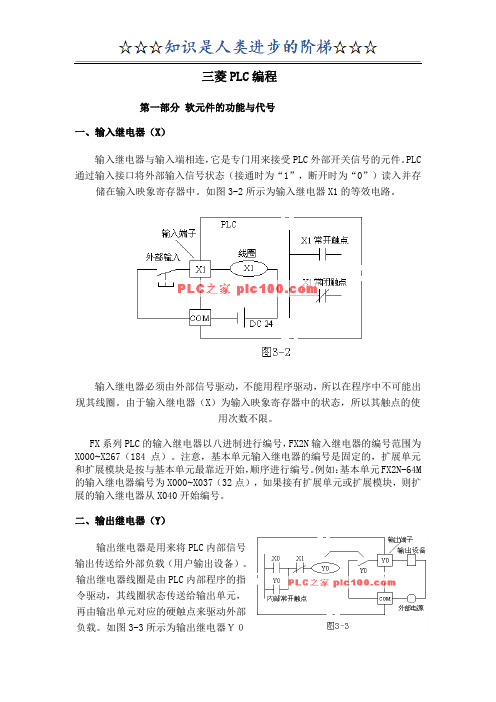
三菱PLC编程第一部分软元件的功能与代号一、输入继电器(X)输入继电器与输入端相连,它是专门用来接受PLC外部开关信号的元件。
PLC 通过输入接口将外部输入信号状态(接通时为“1”,断开时为“0”)读入并存储在输入映象寄存器中。
如图3-2所示为输入继电器X1的等效电路。
输入继电器必须由外部信号驱动,不能用程序驱动,所以在程序中不可能出现其线圈。
由于输入继电器(X)为输入映象寄存器中的状态,所以其触点的使用次数不限。
FX系列PLC的输入继电器以八进制进行编号,FX2N输入继电器的编号范围为X000~X267(184点)。
注意,基本单元输入继电器的编号是固定的,扩展单元和扩展模块是按与基本单元最靠近开始,顺序进行编号。
例如:基本单元FX2N-64M 的输入继电器编号为X000~X037(32点),如果接有扩展单元或扩展模块,则扩展的输入继电器从X040开始编号。
二、输出继电器(Y)输出继电器是用来将PLC内部信号输出传送给外部负载(用户输出设备)。
输出继电器线圈是由PLC内部程序的指令驱动,其线圈状态传送给输出单元,再由输出单元对应的硬触点来驱动外部负载。
如图3-3所示为输出继电器Y0的等效电路。
图3-3 输出继电器的等效电路每个输出继电器在输出单元中都对应有维一一个常开硬触点,但在程序中供编程的输出继电器,不管是常开还是常闭触点,都可以无数次使用。
FX系列PLC的输出继电器也是八进制编号其中FX2N编号范围为Y000~Y267(184点)。
与输入继电器一样,基本单元的输出继电器编号是固定的,扩展单元和扩展模块的编号也是按与基本单元最靠近开始,顺序进行编号。
在实际使用中,输入、输出继电器的数量,要看具体系统的配置情况。
三、通用辅助继电器(M0~M499)FX2N系列共有500点通用辅助继电器。
通用辅助继电器在PLC运行时,如果电源突然断电,则全部线圈均OFF。
当电源再次接通时,除了因外部输入信号而变为ON的以外,其余的仍将保持OFF状态,它们没有断电保护功能。
法兰克系统m指令大全

法兰克系统m指令大全一、指令概述法兰克系统m指令是用于控制法兰克机器人运动和操作的命令集合。
m指令主要用于程序编程和机器人操作,可以实现机器人的各种功能和动作。
本文将详细介绍法兰克系统的m指令大全,包括常用指令、参数说明和示例应用。
二、常用指令列表1. MOVJMOVJ指令用于将机器人关节移动到指定位置。
MOVJ J1=30.0 J2=20.0 J3=10.0 J4=0.0 J5=5.0 J6=0.0 FINE•J1-J6:各关节角度•FINE:表示进行精细插补2. MOVLMOVL指令用于将机器人末端执行器移动到指定位置。
MOVL X=100.0 Y=50.0 Z=30.0 A=90.0 B=0.0 C=0.0 FINE•X,Y,Z:末端执行器位置•A,B,C:末端执行器姿态•FINE:表示进行精细插补3. SPEEDSPEED指令用于设置机器人的速度。
SPEED X=100.0 Y=50.0 Z=30.0 A=90.0 B=0.0 C=0.0•X,Y,Z:线性速度•A,B,C:角速度4. WAITWAIT指令用于等待特定条件满足后继续执行程序。
WAIT $(COND)•COND:等待的条件三、参数说明•关节角度范围:-180~180度•位置坐标范围:-1000~1000mm•姿态角度范围:-180~180度四、示例应用示例一:绘制正方形MOVJ J1=0 J2=0 J3=0 J4=0 J5=0 J6=0 FINEMOVL X=100 Y=0 Z=0 A=0 B=0 C=0 FINEMOVL X=100 Y=100 Z=0 A=0 B=0 C=0 FINEMOVL X=0 Y=100 Z=0 A=0 B=0 C=0 FINEMOVL X=0 Y=0 Z=0 A=0 B=0 C=0 FINE示例二:圆周运动SPEED X=50 Y=50 Z=50 A=50 B=50 C=50MOVJ J1=0 J2=0 J3=0 J4=0 J5=0 J6=0 FINEMOVL X=100 Y=0 Z=0 A=0 B=0 C=0 FINEMOVL X=50 Y=86.6 Z=0 A=0 B=0 C=0 FINEMOVL X=-50 Y=86.6 Z=0 A=0 B=0 C=0 FINEMOVL X=-100 Y=0 Z=0 A=0 B=0 C=0 FINEMOVL X=-50 Y=-86.6 Z=0 A=0 B=0 C=0 FINEMOVL X=50 Y=-86.6 Z=0 A=0 B=0 C=0 FINEMOVL X=100 Y=0 Z=0 A=0 B=0 C=0 FINE五、总结以上是法兰克系统m指令的大全,通过学习和掌握这些指令,可以更好地进行法兰克机器人的编程和操作,实现各种复杂动作和任务。
modbus指令口诀
modbus指令口诀Modbus是一种用于在工业控制系统中传输数据的通信协议。
它是一种开放的协议,可以用于各种设备之间的通信,如传感器、仪器、PLC(可编程逻辑控制器)等。
在Modbus通信中,主要有几个常用的指令。
下面我将为你介绍这些指令的功能和用法。
1. Read Holding Registers(读保持寄存器):这个指令用于从设备中读取保持寄存器的值。
保持寄存器是Modbus设备用于存储数据的一种寄存器。
通过该指令,主站可以向从站发送请求,并获取从站的保持寄存器中的数据。
2. Write Single Register(写单个寄存器):这个指令用于向设备的保持寄存器中写入数据。
它允许主站向从站发送请求,并将数据写入从站的一个保持寄存器中。
这可以用于向设备发送命令或配置参数。
3. Read Input Registers(读输入寄存器):这个指令用于从设备中读取输入寄存器的值。
输入寄存器是Modbus设备用于接收外部输入信号的一种寄存器。
通过该指令,主站可以向从站发送请求,并获取从站的输入寄存器中的数据。
4. Write Multiple Registers(写多个寄存器):这个指令用于向设备的多个保持寄存器中写入数据。
它允许主站向从站发送请求,并将数据写入从站的多个保持寄存器中。
这可以用于同时写入多个参数或配置信息。
5. Read Coils(读线圈):这个指令用于从设备中读取线圈的状态。
线圈是Modbus设备中的开关量输入或输出信号。
通过该指令,主站可以向从站发送请求,并获取从站的线圈的状态。
6. Write Single Coil(写单个线圈):这个指令用于向设备的一个线圈中写入数据。
它允许主站向从站发送请求,并将数据写入从站的一个线圈中。
这可以用于控制设备的开关量输出。
7. Read Exception Status(读异常状态):这个指令用于从设备中读取异常状态的值。
异常状态是指Modbus设备内部可能发生的错误或异常情况。
move指令的用法plc -回复
move指令的用法plc -回复PLC (Programmable Logic Controller) 是一种常用于自动化控制系统中的电子设备。
PLC 通常用于监控和控制各种物理过程,例如工业生产线、机器操作以及建筑设施。
在编程PLC时,move指令是一种常用的指令,它用于将数据从一个位置移动到另一个位置。
本文将详细介绍move指令的用法和应用。
首先,我们需要了解在PLC编程中使用的编程语言。
PLC编程语言有多种选择,例如LD (Ladder Diagram)、FBD (Function Block Diagram)、IL (Instruction List)以及ST (Structured Text)等。
在本文中,我们将使用最常见的LD语言进行讲解。
在LD语言中,move指令的语法如下:MOV Source, Destination其中,Source代表数据的来源,可以是常数、寄存器、变量等;Destination 代表数据的目的地,也可以是寄存器、变量等。
move指令的功能非常简单明了,它将Source中的数据移动到Destination中。
在PLC的执行过程中,move指令在两个操作数之间执行数据传输,从而实现数据的复制和移动。
接下来,我们将逐步解释move指令的用法和应用。
第一步,选择Source和Destination的数据类型。
在PLC中,数据通常有不同的类型,例如布尔型、整数型、浮点型等。
在编写move指令之前,我们需要确定每个操作数的数据类型,并确保两个操作数是兼容的。
例如,我们想要将一个整数型的寄存器R1中的数据移动到另一个整数型的寄存器R2中,我们可以将Source设置为R1,Destination设置为R2。
第二步,确定move指令的执行条件。
在PLC编程中,我们可以使用位运算或者条件语句来控制move指令的执行条件。
这样可以根据不同的需求和情景进行灵活的控制。
例如,我们可以设置一个触发条件,当某个输入信号为1时,move指令才会执行。
modbus指令构造
modbus指令构造一、读取线圈状态(Read Coils)指令Read Coils指令用于读取远程设备的线圈状态。
发送方通过该指令向目标设备请求读取指定线圈的状态,并接收目标设备返回的线圈状态信息。
该指令的功能码为01,数据域包含读取起始地址和读取数量两个字段。
二、读取离散输入状态(Read Discrete Inputs)指令Read Discrete Inputs指令用于读取远程设备的离散输入状态。
发送方通过该指令向目标设备请求读取指定离散输入的状态,并接收目标设备返回的离散输入状态信息。
该指令的功能码为02,数据域包含读取起始地址和读取数量两个字段。
三、读取保持寄存器(Read Holding Registers)指令Read Holding Registers指令用于读取远程设备的保持寄存器的值。
发送方通过该指令向目标设备请求读取指定保持寄存器的值,并接收目标设备返回的保持寄存器值信息。
该指令的功能码为03,数据域包含读取起始地址和读取数量两个字段。
四、读取输入寄存器(Read Input Registers)指令Read Input Registers指令用于读取远程设备的输入寄存器的值。
发送方通过该指令向目标设备请求读取指定输入寄存器的值,并接收目标设备返回的输入寄存器值信息。
该指令的功能码为04,数据域包含读取起始地址和读取数量两个字段。
五、写单个线圈(Write Single Coil)指令Write Single Coil指令用于向远程设备写入单个线圈的状态。
发送方通过该指令向目标设备发送设置某个线圈的状态信息,并接收目标设备返回的响应。
该指令的功能码为05,数据域包含待写入线圈的地址和状态两个字段。
六、写单个保持寄存器(Write Single Register)指令Write Single Register指令用于向远程设备写入单个保持寄存器的值。
发送方通过该指令向目标设备发送设置某个保持寄存器的值信息,并接收目标设备返回的响应。
1500运动控制常见功能所用编程指令
点动功能点动功能至少需要MC_Power,MC_Reset,和MC_Jog指令。
相对距离运行相对速度控制功能,需要MC_Power,MC_Reset,和MC_MoveRelative指令。
以速度连续运行相对速度控制功能,需要MC_Power,MC_Reset,和MC_MoveVolcity,以及MC_Halt 指令。
启用/禁用工艺对象:MC_Power确认报警.重新启动工艺对象Mc_rest相对定位轴:Mc_MoveVelocity暂停轴:MC_haltS7-1200运动控制指令用户组态轴的参数,通过控制面板调试成功后,就可以开始根据工艺要求编写控制程序了。
关于运动控制指令有几点需要说明:1. 打开OB1块,在Portal软件右侧“指令”中的“工艺”中找到“运动控制”指令文件夹,展开“S7-1200 MotionControl”可以看到所有的S7-1200运动控制指令。
可以使用拖拽或是双击的方式在程序段中插入运动指令,如下图所示,以MC_Power指令为例,用拖拽方式说明如何添加Motion Control指令。
这些Motion Control指令插入到程序中时需要背景数据块,如下图所示,可以选择手动或是自动生成DB块的编号。
添加好背景DB后的MC_Power指令如下图所示。
『注意』运动控制指令之间不能使用相同的背景DB,最方便的操作方式就是在插入指令时让Portal软件自动分配背景DB块。
2. 运动控制指令的背景DB块在“项目树”-->“程序块”--> “系统块”-->“程序资源”中找到。
用户在调试时可以直接监控该DB块中的数值,如下图所示。
3. 每个轴的工艺对象都一个背景DB块,用户可以通过下面的方式打开这个背景DB块:可以对DB块中的数值进行监控或是读写。
以实时读取“轴_1”的当前位置为例,如下图所示,轴_1的DB块号为DB1,用户可以在OB1调用MOVE指令,在MOVE指令的IN端输入:DB1.Position,则Portal软件会自动把DB1.Position更新成:“轴_1”.Position。
- 1、下载文档前请自行甄别文档内容的完整性,平台不提供额外的编辑、内容补充、找答案等附加服务。
- 2、"仅部分预览"的文档,不可在线预览部分如存在完整性等问题,可反馈申请退款(可完整预览的文档不适用该条件!)。
- 3、如文档侵犯您的权益,请联系客服反馈,我们会尽快为您处理(人工客服工作时间:9:00-18:30)。
Special Function Blocks Programming Guide0742-901-2901-005PrefaceScope of the User GuideThis programming guide provides basic information about all special function blocks. This information helps users to configure and create program code for a MOX system application. It is expected that the user is an engineer or similar with an understanding of the operating and programming requirements of the intended MOX system components.Related DocumentsA MOX system contains a collection of MOX equipment and several software packages. For thisreason, a number of related documents should be read in conjunction with this guide.The related documents are noted below:MoxIDE User GuideMoxGRAF User GuideMOX Open Controller User GuideMOX Unity Field Controller User GuideMOX IoNix Field Controller User GuideContents1 OVERVIEW (1)2 FUNCTION BLOCK DESCRIPTION (3)2.1 AGA3 (3)2.1.1 Calling Parameters (3)2.1.2 Return Parameters (3)2.1.3 Unit Conversion (4)2.2 AGA7 (6)2.2.1 Calling Parameters (6)2.2.2 Return Parameters (6)2.2.3 Unit Conversion (6)2.3 AGA8D (8)2.3.1 Calling Parameters (8)2.3.2 Return Parameters (9)2.3.3 Composition (9)2.4 AGA8G (10)2.4.1 Calling Parameters (10)2.4.2 Return Parameters (11)2.4.3 Composition (11)2.5 A MMETER645 (12)2.5.1 Calling Parameters (12)2.5.2 Return Parameters (13)2.5.3 Hints, Tips and FAQs (14)2.6 A MMETER WS (18)2.6.1 Calling Parameters (18)2.6.2 Return Parameters (19)2.6.3 Hints, Tips and FAQs (20)2.7 C OM X (21)2.7.1 Calling Parameters (21)2.7.2 Return Parameters (22)2.8 DT IME (23)2.8.1 Calling Parameters (23)2.8.2 Return Parameters (23)2.9 E MAIL T X (24)2.9.1 Calling Parameters (24)2.9.2 Return Parameters (24)2.9.3 Hints, Tips and FAQs (24)2.10 E MAIL R X (26)2.10.1 Calling Parameters (26)2.10.2 Return Parameters (26)2.10.3 Hints, Tips and FAQs (27)2.11 E TH2C OM (28)2.11.1 Calling Parameters (28)2.11.2 Return Parameters (28)2.12 F_C ONTROL (29)2.12.1 Calling Parameters (29)2.12.2 Return Parameters (29)2.12.3 Hints, Tips and FAQs (30)2.13 F_RW (31)2.13.1 Calling Parameters (31)2.13.2 Return Parameters (31)2.13.3 Hints, Tips and FAQs (31)2.14 F ILE T RANS (33)2.14.1 Calling Parameters (33)2.14.2 Return Parameters (34)2.14.3 Hints, Tips and FAQs (34)2.15 F RAME G RAB (35)2.15.1 Calling Parameters (35)2.15.2 Return Parameters (36)2.15.3 View Utility (36)2.15.4 Hints, Tips and FAQ (37)2.16 GPRS (38)2.16.1 Calling Parameters (38)2.16.2 Return Parameters (40)2.16.3 Hints, Tips and FAQs (41)2.17 M OD B US M (42)2.17.1 Calling Parameters (42)2.17.2 Return Parameters (43)2.17.3 Hints, Tips and FAQs (43)2.18 M ODEM (44)2.18.1 Calling Parameters (44)2.18.2 Return Parameters (46)2.18.3 Usage (46)2.18.4 Hints, Tips, and FAQs (48)2.19 M OD N ET M (51)2.19.1 Calling Parameters (51)2.19.2 Return Parameters (52)2.20 M OX G ET T IME (53)2.20.1 Calling Parameters (53)2.20.2 Return Parameters (53)2.21 M OX L OG (54)2.21.1 Calling Parameters (54)2.21.2 Return Parameters (55)2.21.3 MoxLog Viewer Utility (55)2.21.4 .CSV File Format (59)2.21.5 Hints, Tips and FAQs (60)2.22 M OX R X T X (61)2.22.1 Calling Parameters (61)2.22.2 Return Parameters (62)2.22.3 Hints, Tips and FAQs (62)2.23 M OX S ET T IME (64)2.23.1 Calling Parameters (64)2.23.2 Return Parameters (64)2.24 MXP OWER (65)2.24.1 Calling Parameters (65)2.24.2 Return Parameters (65)2.25 P ING (66)2.25.1 Calling Parameters (66)2.25.2 Return Parameters (66)2.25.3 Hints, Tips and FAQs (67)2.26 PPP (68)2.26.1 Calling Parameters (68)2.26.2 Return Parameters (68)2.27 S OCKET (69)2.27.1 Calling Parameters (69)2.27.2 Return Parameters (70)2.27.3 Hints, Tips and FAQs (70)2.28 S YS I NFO (71)2.28.1 Calling Parameters (71)2.28.2 Return Parameters (71)2.29 T EMPERATURE (72)2.29.1 Calling Parameters (72)2.29.2 Return Parameters (72)2.30 UPSC ONF (73)2.30.1 Calling Parameters (73)2.30.2 Return Parameters (74)2.31 UPSM ONITOR (76)2.31.1 Calling Parameters (76)2.31.2 Return Parameters (76)2.32 W ATCH D OG (78)2.32.1 Calling Parameters (78)2.32.2 Return Parameters (78)APPENDIX A PRODUCT SUPPORT (79)FiguresFigure 1 HMI-Modem-Modem-RTU Link (48)Figure 2 RTU-Modem-RTU Link (49)Figure 3 MoxLog Viewing Utility (55)Figure 4 MoxLog Device Select (56)Figure 5 MoxLog Device Operation (57)Figure 6 MoxLog Device Read (58)Figure 7 MoxLog Record View (58)Figure 8 MoxLog Data Format Options (59)Figure 9 Configuring the Protocol of the Serial Port for MoxRxTx (62)Figure 10 Configure Network for MoxRxTx (63)TablesTable 1 Function Blocks Available for MOX Open Controller (1)Table 2 Function Blocks Available for the MOX Unity and the MOX IoNix (2)Table 3 Calling Parameters of AGA3 (3)Table 4 Return Parameters of AGA3 (3)Table 5 Pressure Conversion (4)Table 6 Temperature Conversion (4)Table 7 Density Conversion (5)Table 8 Gross Heating Value Conversion (5)Table 9 Calling Parameters of AGA7 (6)Table 10 Return Parameters of AGA7 (6)Table 11 Pressure Conversion of AGA7 (7)Table 12 Temperature Conversion of AGA7 (7)Table 13 Calling Parameters of AGA8d (8)Table 14 Return Parameters of AGA8d (9)Table 15 Calling Parameters of AGA8g (10)Table 16 Return Parameters of AGA8g (11)Table 17 Calling Parameters of Ammeter645 (13)Table 18 Return Parameters of Ammeter645 (14)Table 19 Calling Parameters of AmmeterWS (19)Table 20 Return Parameters of AmmeterWS (19)Table 21 Calling Parameters of ComX (21)Table 22 Return Parameters of ComX (22)Table 23 Calling Parameters of DTime (23)Table 24 Return Parameters of DTime (23)Table 25 Calling Parameters of EmailTx (24)Table 26 Return Parameters of EmailTx (24)Table 27 Calling Parameters of EmailRx (26)Table 28 Return Parameters of EmailRx (26)Table 29 Calling Parameters of Eth2Com (28)Table 30 Return Parameters of Eth2Com (28)Table 31 Calling Parameters of F_Control (29)Table 32 Return Parameters of F_Control (29)Table 33 Calling Parameters of F_RW (31)Table 34 Return Parameters of F_RW (31)Table 35 MODBUS Address Map Variables (32)Table 36 Calling Parameters of FileTrans (33)Table 37 Return Parameters of FileTrans (34)Table 38 Calling Parameters FrameGrab (35)Table 39 Return Parameters of FrameGrab (36)Table 40 Calling Parameters of GPRS (40)Table 41 Return Parameters of GPRS (40)Table 42 Calling Parameters of ModBusM (43)Table 43 Return Parameters of ModBusM (43)Table 44 Calling Parameters of Modem (45)Table 45 Return Parameters of Modem (46)Table 46 Calling Parameters of ModNetM (52)Table 47 Return Parameters of ModNetM (52)Table 48 Calling Parameters of MoxGetTime (53)Table 49 Return Parameters of MoxGetTime (53)Table 50 Calling Parameters of MoxLog (55)Table 51 Return Parameters of MoxLog (55)Table 52 Calling Parameters of MoxRxTx (61)Table 53 Return Parameters of MoxRxTx (62)Table 54 Calling Parameters of MoxSetTime (64)Table 55 Return Parameters of MoxSetTime (64)Table 56 Calling Parameters of MXPower (65)Table 57 Return Parameters of MXPower (65)Table 58 Calling Parameters of Ping (66)Table 59 Return Parameters of Ping (66)Table 60 Calling Parameters of PPP (68)Table 61 Return Parameters of PPP (68)Table 62 Calling Parameters of Socket (69)Table 63 Return Parameters of Socket (70)Table 64 IP Settings in Different Rolls (70)Table 65 Calling Parameters of SysInfo (71)Table 66 Return Parameters of SysInfo (71)Table 67 Calling Parameters of Temperature (72)Table 68 Return Parameters of Temperature (72)Table 69 Calling Parameters of UPSConf (74)Table 70 Return Parameters of UPSConf (75)Table 71 Calling Parameters of UPSMonitor (76)Table 72 Return Parameters of UPSMonitor (77)Table 73 Calling Parameters of WatchDog (78)Table 74 Return Parameters of WatchDog (78)1OverviewMoxGRAF supports special function blocks to extend the functionality of the MOX Open Controller, MOX Unity and MOX IoNix. The following tables give function block names and their description supported by different controllers.For the MOX Open ControllerDescriptionDTime Digital data dalayEth2Com Ethernet to serial port processmasterModNetM ModNetMoxGetTime ReadtimesystemMoxSetTime Set system timeoperationSocket TCP/IPSysInfo SysteminformationTable 1 Function Blocks Available for MOX Open ControllerFor the MOX Unity and the MOX IoNixDescriptionAGA3 AGA3 orifice metering of natural gasAGA7 AGA7 gas measurementAGA8D AGA8 detail characterization methodAGA8G AGA8 gross characterization methodAmmeter645 Ammeter645accessdataAmmeterWS Ammeter data access for WeiShengComX Comm port processreceivingEmailRx EmailsendingEmailTx EmailEth2Com Ethernet to serial port processF_Control Open, close and delete the fileF_RW Read from or write to the filetransferFileTrans FileFrameGrab FramegrabberGPRS GPRSmasterModBusM ModBusModem ModemprocessmasterModNetM ModNettimesystemMoxGetTime ReaddataMoxLog LogMoxRxTX Read or write remote dataMoxSetTime Set system timeMXPower Detect the MOX Unity power supplierPing Ping Destination IPPPP ppp connection managementoperationSocket TCP/IPSysInfo System informationTemperature Detect the CPU board temperatureUPSConf UPSconfigurationmonitoringUPSMonitor UPSWatchDog Watch dog timerTable 2 Function Blocks Available for the MOX Unity and the MOX IoNix2Function Block Description2.1AGA3The “AGA3” function block calculates natural gas flow through a flange-tapped, concentric orifice meter.The calculation is based on the “Orifice Metering of Natural Gas and Other Related Hydrocarbon Fluids”, Part3 Natural Gas Applications, AGA Report No. 3, Third Edition, August 1992.2.1.1Calling ParametersName Data Type DescriptionEN BOOL Enable this function block0: Disable1: EnableCT DINT Perform a calculation in CT msP REAL Upstream pressure in BardP REAL Orifice differential pressure in mbarT REAL Temperature in degree CelsiusDEN REAL Density in Kg/m^3BDEN REAL Standard density in Kg/m^3D REAL Meter tube internal diameter calculatedat flowing temperature (mm)dd REAL Orifice plate bore diameter calculated atflowing temperature. (mm)u REAL Viscosity in cPExponentIsentropicK REALReservedRe1 REALReservedRev2 REALReservedRe3 REALTable 3 Calling Parameters of AGA32.1.2Return ParametersName Data Type DescriptionstatusCalculationSt SINTQM REAL Mass flow rate (Kg/s)QB REAL Volume flow rate at standard conditions. (m^3/s)QL REAL Volume flow rate at flowing (actual) conditions. (m^3/s)ReD REAL Pipe Reynolds numberReservedRev REALTable 4 Return Parameters of AGA32.1.3Unit ConversionCare should be taken with the unit of input/output parameters. A list of the unit conversions isprovided below.2.1.3.1.Pressure ConversionsFrom To Usepsia MPaVALUE*0.006894757VALUE*0.1bar MPaVALUE*0.000133322 mmHg MPaatm MPaVALUE*0.101325 Mpa gage MPa VALUE + 0.101325(VALUE+14.696)*0.006894757 psig MPabar gage MPa (VALUE+1.01325)*0.1atm gage MPa (VALUE+1.0)*0.101325mmHg gage MPa (VALUE+760)*0.00133322)VALUE/0.006894757 MPa psiaVALUE*10MPa barVALUE/0.00013322MPa mmHgVALUE/0.101325MPa atmVALUE-0.101325MPa MPagageMPa psig VALUE/0.006894757 – 14.696MPa bar gage VALUE * 10 – 1.01325MPa atm gage VALUE/0.10325 –1MPa mmHg gage VALUE/0.000133322 -760Table 5 Pressure Conversion2.1.3.2.Temperature ConversionsFROM To Useo C K VALUE + 273.15o R KVALUE*5/9o F K5/9*(VALUE+459.67) K o C VALUE – 273.15K o R VALUE*9/5K o F VALUE*9/5 – 459.67Table 6 Temperature Conversion2.1.3.3.Density ConversionsFrom To Usekg/m3 mol/dm3VALUE/MWlbm/ft3 mol/dm3VALUE*16.01846/MWm3/kg mol/dm3 1.0/(VALUE*MW)ft3/lbm mol/dm3 16.01846/(VALUE*MV)mol/dm3 kg/m3 VALUE*MWmol/dm3 lbm/ft3VALUE*MW/16.01846mol/dm3m3/kg 1.0/(VALUE*MW)mol/dm3 ft3/lbm 16.01846/(VALUE*MW)Table 7 Density ConversionMW: Molecular Weight (Kg/Mol).2.1.3.4.Gross Heating Value ConversionsFrom To UseBtu/ft3 KJ/dm3VALUE*1.055056/28.316846592Btu/in3 KJ/dm3VALUE*1.055056/0.016387064kcal/m3 KJ/dm3VALUE*4.184*10-3MJ/m3 KJ/dm3VALUEKJ/m3 KJ/dm3VALUE*10-3KJ/dm3 Btu/ft3VALUE*28.316846592/1.055056KJ/dm3 Btu/in3VALUE*0.016387064/1.055056KJ/dm3 kcal/m3 VALUE/(4.184*10-3)KJ/dm3 MJ/m3 VALUEKJ/dm3 KJ/m3 VALUE*103Table 8 Gross Heating Value Conversion2.1.3.5.Standard ConditionsTemperature: 20o CPressure: 1 atm2.2AGA7The “AGA7” function block calculates the gas volumetric flow from flowing conditions to standard conditions. The calculation is based on the “Measurement of Gas by Turbine Meters”, AGA Transmission Measurement Committee Report No. 7, Second Revision, April 1996.2.2.1Calling ParametersName Data Type DescriptionEN BOOL Enable this function block0: Disable calculation1: Enable calculationCT DINT Perform a calculation in CT msPf REAL Pressure at flowing conditions in MPaTf REAL Temperature at flowing conditions in degree CelsiusZf REAL Compressibility at flowing conditionsQf REAL Flow rate at flowing conditions in cubic metres/secondPb REAL Pressure at standard conditions in MPaTb REAL Temperature at standard conditions in degree CelsiusZb REAL Compressibility at standard conditionsTable 9 Calling Parameters of AGA72.2.2 Return ParametersName Data Type DescriptionST SINT CalculationstatusQb REAL Flow rate at standard conditions in cubic metres/secondTable 10 Return Parameters of AGA72.2.3Unit ConversionCare should be taken with the units associated with the input/output parameters. A list of the unit conversions is provided below.2.2.3.1.Pressure ConversionsFrom To UseVALUE*0.006894757psia MPaVALUE*0.1bar MPaVALUE*0.000133322mmHg MPaVALUE*0.101325atm MPaMpa gage MPa VALUE + 0.101325(VALUE+14.696)*0.006894757psig MPabar gage MPa (VALUE+1.01325)*0.1atm gage MPa (VALUE+1.0)*0.101325mmHg gage MPa (VALUE+760)*0.00133322)VALUE/0.006894757MPa psiaVALUE*10MPa barVALUE/0.00013322MPa mmHgMPa atmVALUE/0.101325gageVALUE-0.101325MPa MPaMPa psig VALUE/0.006894757 – 14.696MPa bar gage VALUE * 10 – 1.01325MPa atm gage VALUE/0.10325 –1MPa mmHg gage VALUE/0.000133322 -760Table 11 Pressure Conversion of AGA72.2.3.2.Temperature ConversionsFrom To Useo C K VALUE + 273.15o R KVALUE*5/9o F K5/9*(VALUE+459.67)K o C VALUE – 273.15K o R VALUE*9/5K o F VALUE*9/5 – 459.67Table 12 Temperature Conversion of AGA72.3AGA8dThe “AGA8d” function block calculates the compressibility factors of natural gas and other related hydrocarbon gases.The calculation is based on the “Compressibility Factors of Natural Gas and Other Related Hydrocarbon Gases”, AGA Transmission Measurement Committee Report No. 8, Second Edition, November 1992.The AGA report No.8 provides 2 methods to calculate the compressibility, one is the detailed characterization method and the other is the gross characterization method. The function block AGA8d is based on the detailed characterization method.2.3.1Calling ParametersName Data Type Descriptionen BOOL Enable this function block0: Disable calculation1: Enable calculationCT DINT Perform a calculation in CT msC1 REAL Composition (% Mole) of MethaneN2 REAL Composition (% Mole) of NitrogenCO2 REAL Composition (% Mole) of Carbon dioxideC2 REAL Composition (% Mole) of EthaneC3 REAL Composition (% Mole) of PropaneH20 REAL Composition (% Mole) of waterH2S REAL Composition (% Mole) of Hydrogen sulfideH REAL Composition (% Mole) of HydrogenCO REAL Composition (% Mole) of Carbon monoxideO2 REAL Composition (% Mole) of OxygenComposition(% Mole) of iso-ButaneiC4 REALnC4 REAL Composition (% Mole) of n-ButaneiC5 REAL Composition (% Mole) of iso-PentanenC5 REAL Composition (% Mole) of n-PentanenC6 REAL Composition (% Mole) of n-HexanenC7 REAL Composition (% Mole) of n-HeptanenC8 REAL Composition (% Mole) of n-OctanenC9 REAL Composition (% Mole) of n-NonanenC10 REAL Composition (% Mole) of n-Decane(% Mole) of heliumHe REALCompositionAr REAL Composition (% Mole) of ArgonT REAL Temperature in degree CelsiusP REAL Pressure in BarReservedRe1 REALTable 13 Calling Parameters of AGA8d2.3.2 Return ParametersName Data Type DescriptionstatusStatus SINTCalculationCompressibilityZ REALD REAL Density in Kg/(m^3)Mol Weight (Kg/Mol)CompositionCMW REALBD REAL Density at standard conditionTable 14 Return Parameters of AGA8d2.3.3CompositionDividing each component’s mole percent by the sum of all the component’s mole percents will normalize the mole percent values.The mole percent value should be 0 for components that are not present.2.4AGA8gThe “AGA8g” function block calculates the compressibility factors of natural gas and other related hydrocarbon gases.The calculation is based on the “Compressibility Factors of Natural Gas and Other Related Hydrocarbon Gases”, AGA Transmission Measurement Committee Report No. 8, Second Edition, November 1992.The AGA report No.8 provides two methods to calculate the compressibility, one is the detailed characterization method and the other is the gross characterization method. The function block AGA8g is based on the gross characterization method.2.4.1Calling ParametersName Data Type Descriptionen BOOL Enable this function block0: Disable calculation1: Enable calculationCT DINT Perform a calculation in CT msmethod SINT Methods for determining equivalent hydrocarbon propertiesMPainPressureP REALT REAL Temperature in degree CelsiusHV REAL Composition (% Mole) of Methane in KJ/dm^3TH REAL Reference temperature for heating value in degree CelsiusTD REAL Reference temperature for molar density in degree Celsiuspressure for molar density in MPaReferencePD REALdensity(specific gravity)RelativeGR REALTGR REAL Reference temperature for relative density in degree CelsiusPGR REAL Reference pressure for relative density in MPaN2 REAL Composition (% Mole) of NitrogenCO2 REAL Composition (% Mole) of Carbon dioxideH REAL Composition (% Mole) of HydrogenCO REAL Composition (% Mole) of Carbon monoxideReservedRe1 REALTable 15 Calling Parameters of AGA8g2.4.2Return ParametersName Data Type DescriptionstatusCalculationStatus SINTCompressibilityZ REALSupercompressibilityFPV REALD REAL Density in Kg/(m^3)Mol Weight (Kg/Mol)CMW REALCompositionBD REAL Density at standard conditionTable 16 Return Parameters of AGA8g2.4.3CompositionDividing each component’s mole percent by the sum of all the component’s mole percents will normalize the mole percent values.For non-existing components, the mole percent value should be 0.2.5Ammeter645The “Ammeter645” function block is used to access the Multi-function watt-hour meter via serial port (RS485/RS232). It uses the Multi-function watt-hour meter communication protocol DL/T 645-1997 published by power industry department of China on Feb 02, 1998. This standard was implemented on Jun 01, 1998.2.5.1Calling ParametersName Data Type DescriptionEN BOOL Enable this function block0: Disable1: EnablePORT SINT Serial Port number1: COM12: COM23: COM34: COM4BaudRateBAUD DINTBitsDataDATB SINTParityPAT SINT0: None1: Odd2: EvenBitsSTPB SINTStop1: One stop2: Two stopsmodeSerialMODE SINT1: RS2322: RS485CommandCMND SINT1: Read2: Continue Read3: Retry Read4: Write5: Adjust Date and Time6: Write Device Address7: Set Baud Rate8: Set Password9: ClearDATY SINTTypeDataADR0 SINTAddressThe first address1AddressADR1 SINTThe second address2AddressADR2 SINTThe third addressAddress3ADR3 SINTThe fourth addressAddress4ADR4 SINTThe fifth address5ADR5 SINTAddressThe sixth addressName Data Type DescriptionDID0 SINT Data ID 0The first Data IDDID1 SINT Data ID 1The second data IDDLIN SINT Data Length InputThe Input Data BytesInputDataNDIN DINTDINTInputDataRealFDIN REALDIN0 SINT Data Input 0The first original input byteDIN1 SINT Data Input 1The second original input byteDIN2 SINT Data Input 2The third original input byteDIN3 SINT Data Input 3The fourth original input byteDIN4 SINT Data Input 4The fifth original input byteDIN5 SINT Data Input 5The sixth original input byteTimeoutTOUT DINTTimeout in ms, the default is 5000Table 17 Calling Parameters of Ammeter6452.5.2Return ParametersName Data Type DescriptionStatus.ProcessSTAT SINT-5: STATUS_INVALID_DATA-4: STATUS_INVALID_PARA-3: STATUS_PORT_ERROR-2: STATUS_DATA_ERROR-1: STATUS_TIMEOUT0: INITIAL or RESET OK;1: STATUS_PROCESS2: STATUS_SUCCESSRXOKRXOK BOOLRead complete.A positive pulse indicates the read complete.CodeFunctionFUNC SINTThe return function codeOutputLengthDLEN SINTDataReceived byte numErrorERR SINTThe error code from ammeterOutputDataDINTDOUT DINTDINT Data Output when DATY = 1 for read FOUT REAL REAL Data OutputREAL Data Output when DATY = 2 for read OUT0 SINT Data Output 0The first original byte from ammeterOUT1 SINT Data Output 1The second original byte from ammeterName Data Type DescriptionOUT2 SINT Data Output 2The third original byte from ammeterOUT3 SINT Data Output 3The fourth original byte from ammeterOUT4 SINT Data Output 4The fifth original byte from ammeterOUT5 SINT Data Output 5The sixth original byte from ammeterTable 18 Return Parameters of Ammeter6452.5.3Hints, Tips and FAQs2.5.3.1.Configure the Serial PortThe serial port can be fully configured by input parameters. The default baud rate for the ammeter is 1200 bps while the default parity is even. When the function block is initiated the serial ports will be opened when it is enabled. The serial ports will be closed when the function block is disabled.2.5.age of the Function BlockAll serial port parameters should be set correctly. They cannot be modified during operation.CMND:0: no operation1: ReadInput Pin: CMND, DATY, ADR0 ~ ADR5, DID0, DID1Output Pin: STAT, RXOK, FUNC, DLEN, DOUT or FOUT, OUT0 ~ OUT52: Continue ReadInput Pin: CMND, DATY, ADR0 ~ ADR5, DID0, DID1Output Pin: STAT, RXOK, FUNC, DLEN, DOUT or FOUT, OUT0 ~ OUT53: Retry ReadInput Pin: CMND, DATY, ADR0 ~ ADR5Output Pin: STAT, RXOK, FUNC, DLEN, DOUT or FOUT, OUT0 ~ OUT54: WriteInput Pin: CMND, DATY, ADR0 ~ ADR5, DID0, DID1, NDIN or FDIN, DIN0 ~ DIN5, DLINOutput Pin: STAT, RXOK, FUNC5: Adjust Date and TimeInput Pin: CMND, DIN0 ~ DIN5Output Pin: STAT6: Write Device AddressInput Pin: CMND, ADR0 ~ ADR5Output Pin: STAT, RXOK, FUNC7: Set Baud RateInput Pin: CMND, DIN0Output Pin: STAT, RXOK, FUNC8: Set PasswordInput Pin: CMND, ADR0 ~ ADR5, DID0, DID1, DIN0 ~ DIN5Output Pin: STAT, RXOK, FUNC9: ClearInput Pin: CMND, ADR0 ~ ADR5Output Pin: STATNotes:1) DINT, REAL and Original Bytes can be used for reading and writing. For original bytes, the bytenumber should be defined by the calling parameter DLIN and the physical data should be assigned from DIN0 ~ DIN5.2) DIN0 = ss, DIN1 = mm, DIN2 = hh, DIN3 = DD, DIN4 = MM, DIN5 = YY is for adjusting the Date andTime.3) DIN0 = z is for setting the BaudRate.4) DID0 = PAo, DIN0 = P0o, DIN1 = P1o, DIN2 = P2o,DID1 = PAn, DIN3 = P0n, DIN4 = P1n, DIN5 = P2n is for setting the Password.2.5.3.3.Protocol1) Read DataRequest Packet:68H A0 … A5 68H 01H 02H DI0 DI1 CS 16HNormal Finished Response:68H A0 … A5 68H 81H L DI0 DI1N1 … N m CS 16HNeed to Continue read Response:68H A0 … A5 68H A1H L DI0 DI1N1 … N m CS 16HError Response:68H A0 … A5 68H C1H 01H ERR CS 16H2) Continue ReadRequest Packet:68H A0 … A5 68H 02H 02H DI0 DI1 CS 16HNormal Finished Response:68H A0 … A5 68H 82H L DI0 DI1N1 … N m CS 16HNeed to Continue read Response:68H A0 … A5 68H A2H L DI0 DI1N1 … N m CS 16HError Response:68H A0 … A5 68H C2H 01H ERR CS 16H3) Retry ReadRequest Packet:68H A0 … A5 68H 03H 00H CS 16HNormal Finished Response:68H A0 … A5 68H 83H L DI0 DI1N1 … N m CS 16H Need to Continue read Response:68H A0 … A5 68H A3H L DI0 DI1N1 … N m CS 16H Error Response:68H A0 … A5 68H C3H 01H ERR CS 16H 4) Write DataRequest Packet:68H A0 … A5 68H 04H L DI0 DI1N1 … N m CS 16H Normal Response:68H A0 … A5 68H 84H 00H CS 16HError Response:68H A0 … A5 68H C4H 01H ERR CS 16H 5) Adjust Date and TimeRequest Packet:68H 99H … 99H 68H 08H 06H ss mm hh DD MM YY CS 16H No Response6) Write Device AddressRequest Packet:68H 99H … 99H 68H 0AH 06H A0 …A5 CS 16HNormal Response:68H A0 … A5 68H 8AH 00H CS 16H7) Set Baud RateRequest Packet:68H A0 … A5 68H 0CH 01H Z CS 16HNormal Response:68H A0 … A5 68H 0CH 01H Z CS 16HError Response:68H A0 … A5 68H 8CH 01H Z CS 16H8) Set PasswordRequest Packet:68H A0 … A5 68H 0FH 08H PA0P0o P1o P2o PAN P0N P1N P2N CS 16H Normal Response:68H A0 … A5 68H 8FH 04H PAN P0N P1N P2N CS 16H9) ClearRequest Packet:68H A0 … A5 68H 10H 00H CS 16HNo Response.2.6AmmeterWSThe “AmmeterWS” function block is used to access the Multi-function watt-hour meter via serial ports (RS485/RS232). It uses a special communication protocol from HuNan WeiSheng Electronics Co.LTD. The testing has been done through DTSD341/DSSD331-2. As for other type of WeiShengammeters, please confirm the communication protocol with HuNan WeiSheng Electronics Co. LTD.2.6.1Calling ParametersName Data Type DescriptionEN BOOL Enable this function block0: Disable1: EnablePORT SINT Serial Port Number1: COM12: COM23: COM34: COM4RateBaudBAUD DINTDataBitsDATB SINTParityPAT SINT0: None1: Odd2: EvenBitsStopSTPB SINT1: One stop2: Two stopsModeMODE SINTSerial1: RS2322: RS485CommandCMND SINT1: Read2: Continue Read3: Write Device Address4: Write5: Adjust Date and Time6: Adjust Date and Time for V417: Set PasswordDataTypeDATY SINTAddressAmmeterAADR SINTDALO SINT Data Address LowDAHI SINT Data Address HighDLIN SINT Data Length InputThe Input Data BytesDataInputDINTNDIN DINTInputDataRealFDIN REALDIN0 SINT Data Input 0The first original input byteDIN1 SINT Data Input 1The second original input byteDIN2 SINT Data Input 2The third original input byteDIN3 SINT Data Input 3The fourth original input byte。